EP0436127B1 - Fuel cell - Google Patents
Fuel cell Download PDFInfo
- Publication number
- EP0436127B1 EP0436127B1 EP90123119A EP90123119A EP0436127B1 EP 0436127 B1 EP0436127 B1 EP 0436127B1 EP 90123119 A EP90123119 A EP 90123119A EP 90123119 A EP90123119 A EP 90123119A EP 0436127 B1 EP0436127 B1 EP 0436127B1
- Authority
- EP
- European Patent Office
- Prior art keywords
- channels
- inlet
- gas
- fuel cell
- outlet channels
- Prior art date
- Legal status (The legal status is an assumption and is not a legal conclusion. Google has not performed a legal analysis and makes no representation as to the accuracy of the status listed.)
- Expired - Lifetime
Links
- 239000000446 fuel Substances 0.000 title claims abstract description 44
- 239000012528 membrane Substances 0.000 claims abstract description 20
- 239000003792 electrolyte Substances 0.000 claims abstract description 18
- 239000000376 reactant Substances 0.000 claims abstract description 16
- 230000004888 barrier function Effects 0.000 claims description 6
- 239000011148 porous material Substances 0.000 claims description 6
- 230000005611 electricity Effects 0.000 claims description 4
- 239000011888 foil Substances 0.000 claims description 3
- 229910010293 ceramic material Inorganic materials 0.000 claims description 2
- 210000004027 cell Anatomy 0.000 description 49
- 239000007789 gas Substances 0.000 description 47
- 238000000034 method Methods 0.000 description 13
- 239000000919 ceramic Substances 0.000 description 4
- UFHFLCQGNIYNRP-UHFFFAOYSA-N Hydrogen Chemical compound [H][H] UFHFLCQGNIYNRP-UHFFFAOYSA-N 0.000 description 2
- MCMNRKCIXSYSNV-UHFFFAOYSA-N Zirconium dioxide Chemical compound O=[Zr]=O MCMNRKCIXSYSNV-UHFFFAOYSA-N 0.000 description 2
- QVGXLLKOCUKJST-UHFFFAOYSA-N atomic oxygen Chemical compound [O] QVGXLLKOCUKJST-UHFFFAOYSA-N 0.000 description 2
- 210000003850 cellular structure Anatomy 0.000 description 2
- 239000001257 hydrogen Substances 0.000 description 2
- 229910052739 hydrogen Inorganic materials 0.000 description 2
- 239000000463 material Substances 0.000 description 2
- 239000011159 matrix material Substances 0.000 description 2
- 239000007800 oxidant agent Substances 0.000 description 2
- 230000001590 oxidative effect Effects 0.000 description 2
- 239000001301 oxygen Substances 0.000 description 2
- 229910052760 oxygen Inorganic materials 0.000 description 2
- BASFCYQUMIYNBI-UHFFFAOYSA-N platinum Chemical compound [Pt] BASFCYQUMIYNBI-UHFFFAOYSA-N 0.000 description 2
- 239000000843 powder Substances 0.000 description 2
- 239000007784 solid electrolyte Substances 0.000 description 2
- UGFAIRIUMAVXCW-UHFFFAOYSA-N Carbon monoxide Chemical compound [O+]#[C-] UGFAIRIUMAVXCW-UHFFFAOYSA-N 0.000 description 1
- 229910000990 Ni alloy Inorganic materials 0.000 description 1
- 229910002091 carbon monoxide Inorganic materials 0.000 description 1
- 238000010276 construction Methods 0.000 description 1
- 238000003487 electrochemical reaction Methods 0.000 description 1
- 239000007769 metal material Substances 0.000 description 1
- 238000002156 mixing Methods 0.000 description 1
- 229910000480 nickel oxide Inorganic materials 0.000 description 1
- GNRSAWUEBMWBQH-UHFFFAOYSA-N oxonickel Chemical class [Ni]=O GNRSAWUEBMWBQH-UHFFFAOYSA-N 0.000 description 1
- 229910052697 platinum Inorganic materials 0.000 description 1
- 238000010345 tape casting Methods 0.000 description 1
Images


Classifications
-
- H—ELECTRICITY
- H01—ELECTRIC ELEMENTS
- H01M—PROCESSES OR MEANS, e.g. BATTERIES, FOR THE DIRECT CONVERSION OF CHEMICAL ENERGY INTO ELECTRICAL ENERGY
- H01M8/00—Fuel cells; Manufacture thereof
- H01M8/24—Grouping of fuel cells, e.g. stacking of fuel cells
- H01M8/2465—Details of groupings of fuel cells
- H01M8/2483—Details of groupings of fuel cells characterised by internal manifolds
-
- H—ELECTRICITY
- H01—ELECTRIC ELEMENTS
- H01M—PROCESSES OR MEANS, e.g. BATTERIES, FOR THE DIRECT CONVERSION OF CHEMICAL ENERGY INTO ELECTRICAL ENERGY
- H01M8/00—Fuel cells; Manufacture thereof
- H01M8/24—Grouping of fuel cells, e.g. stacking of fuel cells
- H01M8/241—Grouping of fuel cells, e.g. stacking of fuel cells with solid or matrix-supported electrolytes
- H01M8/242—Grouping of fuel cells, e.g. stacking of fuel cells with solid or matrix-supported electrolytes comprising framed electrodes or intermediary frame-like gaskets
-
- Y—GENERAL TAGGING OF NEW TECHNOLOGICAL DEVELOPMENTS; GENERAL TAGGING OF CROSS-SECTIONAL TECHNOLOGIES SPANNING OVER SEVERAL SECTIONS OF THE IPC; TECHNICAL SUBJECTS COVERED BY FORMER USPC CROSS-REFERENCE ART COLLECTIONS [XRACs] AND DIGESTS
- Y02—TECHNOLOGIES OR APPLICATIONS FOR MITIGATION OR ADAPTATION AGAINST CLIMATE CHANGE
- Y02E—REDUCTION OF GREENHOUSE GAS [GHG] EMISSIONS, RELATED TO ENERGY GENERATION, TRANSMISSION OR DISTRIBUTION
- Y02E60/00—Enabling technologies; Technologies with a potential or indirect contribution to GHG emissions mitigation
- Y02E60/30—Hydrogen technology
- Y02E60/50—Fuel cells
Definitions
- the present invention relates to a fuel cell, in accordance with the generic clause of claim 1.
- Such a fuel cell is already disclosed in a document EP-A-0 289 226, that includes a plurality of series-connected fuel cells, each including an electrically conductive separator, a compressed or sintered oxide powder cathode contacting the separator, a solid electrolyte contacting the cathode, and a compressed or sintered powder anode contacting the electrolyte.
- Each of the separator, anode, electrolyte, and cathode includes two internal holes, each at least partially in registration with each other so that a fuel and an oxygen-containing gas may be admitted to separate tubes in the cell.
- EP-A-0 395 976 discloses a stacked array of fuel cells consisting each of gas permeable anode and cathode sheets, a solid electrolyte sheet of y-doped ZrO2, electrical connecting membranes, and terminal gas manifolds. Within the stack there are arranged a number of gas ducts supplying fuel and oxidant to the respective electrode layers. The gas channels are partially covered with an impermeable material to permit gas transport only to selected layers (e.g. fuel to the anodic layers).
- Conventionally designed fuel cells consist of a thin electrolyte matrix sandwiched between a first and second electrode sheet with first and second porous electrode active layers of e.g. platinum, nickel alloys or nickel oxides, which in the fuel cell constitute the anode and the cathode.
- a first reactant gas consisting of e.g. hydrogen or hydrogen and carbon monoxide, passes over the anode and is absorbed and reacted to the anode surface, while a second reactant gas of oxygen or air passes and reacts over the cathode.
- each fuel cell only produces a voltage of merely about 1 volt, it is necessary to pile and connect many cells to a fuel cell stack in order to obtain voltages for practical purpose.
- Fuel cell stacks may contain several hundreds of single cells, each separated by a separator plate, which prevents blending of the reacting gases and which at the same time serves to collect electrical current.
- the cathode sheet and anode sheet are supplied with reactant gas by means of metallic structures disposed between the anode and the cathode.
- Fuel process gas and oxidant gas are passed through first and second passages, respectively, formed by the metallic structures, which usually are in form of corrugated sheets.
- first and second passages are arranged in different directions, usually in counterflow, parallel flow or transvers fashion, and are served by common external manifolds aligned to the cell faces or by conduits arranged at the edge of the cell.
- a disadvantage of the known cells is, thereby, the thickness of the used materials, which has to be relatively large in order to provide enough rigidity of the cell structure.
- the metallic structures in conventional fuel cells necessarily have a cross-thickness of between 5-10 ml.
- the present invention makes use of a principle allowing the metallic structures entirely or partly to be avoided by reducing the distance gaseous reactants have to pass over the electrode sheets to a distance enabling passage through the porous matrix of the electrodes.
- a fuel cell according to the invention comprises the following components:
- the electrode active layers may, in a particular embodiment of the invention, be composed of several sub-layers, wherein one sublayer has large pores with a pore diameter of preferably more than 10 micrometer, which facilitates the gas transport through the active layer.
- the electrolyte membrane consists of one or more layers of porous ceramic material, which in its pore system is able to secure an electrolyte.
- the membrane may be confined against all gas channels by gas impermeable edge-stripes of e.g. gastight ceramic or metallic materials.
- the ceramic components of the fuel cell according to the invention are supported evenly all over their entire area by omitting the metallic structures.
- the fuel cell according to the invention has thus a greater stability, when transporting the cell, and is more tolerant against gas pressure differences.
- the fuel cell can be constructed with dimensions and for current intensities, which no longer are limited by local gasflow conditions in each cell component.
- a number of the fuel cells according to the invention may advantageously be piled to a fuel cell stack with gas inlet and outlet channels arranged vertically through the stack and with electricity conducting, gastight barriers between each cell.
- the barriers may suitably be constituted by metallic foils or metallic layers applied on the electrode sheets by e.g. tape casting.
- the height of construction of a fuel cell stack may be reduced to 1-2 mm per single cell, which is 5 to 10 times less than in the known cell stacks.
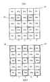
- Fig. 1 & 2 are topviews showing a section of an anode sheet 20 (Fig. 1), and a section of a cathode sheet 40 (Fig. 2), each divided into a number of parallel subareas 1, 2, 3, ..., and provided with gas inlet channels 20i, 40i for an anode process gas and a cathode process gas, respectively, and outlet channels 20e, 40e for anode and cathode exhaust gas, respectively.
- the gas channels are, furthermore, distributed, so that each second subarea 1, 3, 5 ... is provided with alternating series each of an inlet channel 20i, an outlet channel 20e and an inlet channel 20i for anode process gas with interjacent anode active layers 20a (Fig.
- inlet and outlet channels 20i, 20e, 20i, ... alternates in each of subareas 1, 3, 5, ..., so that an inlet channel 20i in subarea 1, corresponds to an outlet channel 20e in subarea 3, and to an inlet channel 20i in subarea 5, etc.
- the inlet channels 40i for cathode process gas and outlet channels 40e for cathode exhaust gas are disposed within interjacent subareas 2, 4, ... , and separated from the anode active layers by gas tight edge-stripes 22, which surround these channels.
- Channels 40i and 40e are arranged intermediate to channels in adjacent subareas.
- the cathode sheet 40 shown in Fig. 2, is constructed similarly to the anode sheet 20 (Fig. 1), except for inlet channels 20i for anode process gas and outlet channels 20e for anode exhaust gas, which in sheet 40 are separated from the surrounding cathode active layers 40a by gastight edge-stripes 22.
- Fig. 3 shows perspectively a section of a fuel cell consisting of an anode sheet 20 and a cathode sheet 40 as described above.
- An electrolyte membrane 30 being provided with corresponding inlet and outlet channels is sandwiched between sheets 20 and 40.
- the electrode sheets and the electrolyte membrane are collected, so that the inlet and outlet channels in the sheets and the membrane are connected to their corresponding channels in the subsequent sheet and membrane.
- anode process gas 25 flows through anode layers 20a in anode sheet 20, after having passed through anode processgas inlet channels 20i arranged in cathode sheet 40 and in electrolyte membrane 30.
- the anode active layers 20a are confined on to sides by gastight stripes 22, surrounding inlet and outlet channels 40i and 40e. Reacted anode processgas is withdrawn from the anode active layers via anode exhaust gas outlet channels 20e through anode sheet 20, and through electrolyte membrane 30 and cathode sheet 40.
- cathode reactant gas 45 flows in cathode sheet 40 through cathode active layers 40a and is withdrawn as cathode exhaust gas 46 through cathode exhaust gas outlet channels 40e.
- the cathode layers 40a in sheet 40 are as in the anode layers 20a in sheet 20 separated from the anode inlet channels and anode outlet channels 20i and 20e by gastight edge-stripes 22.
- the intermediate electrolyte membrane 30 is separated from all gas channels 20i, 20e, 40i, 40e through the membrane, by gastight edge-stripes 22.
- a number of fuel cells shown in Fig. 3 may advantageously be piled to a fuel cell stack, which is shown in Fig. 4.
- Fuel cell stack 100 has gasmanifolding blocks 50 and 51, by which the stack is supplied with cathode reactant gas 45 and anode process gas 25, respectively.
- Stack 100 consists, furthermore, of a number of fuel cells 70, each composed of an anode sheet 20 and a cathode sheet 40 with intermediate electrolyte membrane 30 and constructed and collected as described above.
- An electricity conducting foil 32 is disposed between each single cell.
- Electricity which is produced in cells 70 by electrochemical reaction of process gases 25 and 45 is collected in current collector plates 60 arranged on the upper and lower part of the cell stack 100.
Landscapes
- Life Sciences & Earth Sciences (AREA)
- Engineering & Computer Science (AREA)
- Manufacturing & Machinery (AREA)
- Sustainable Development (AREA)
- Sustainable Energy (AREA)
- Chemical & Material Sciences (AREA)
- Chemical Kinetics & Catalysis (AREA)
- Electrochemistry (AREA)
- General Chemical & Material Sciences (AREA)
- Fuel Cell (AREA)
Abstract
Description
- The present invention relates to a fuel cell, in accordance with the generic clause of
claim 1. - Such a fuel cell is already disclosed in a document EP-A-0 289 226, that includes a plurality of series-connected fuel cells, each including an electrically conductive separator, a compressed or sintered oxide powder cathode contacting the separator, a solid electrolyte contacting the cathode, and a compressed or sintered powder anode contacting the electrolyte. Each of the separator, anode, electrolyte, and cathode includes two internal holes, each at least partially in registration with each other so that a fuel and an oxygen-containing gas may be admitted to separate tubes in the cell.
- Also document EP-A-0 395 976 discloses a stacked array of fuel cells consisting each of gas permeable anode and cathode sheets, a solid electrolyte sheet of y-doped ZrO₂, electrical connecting membranes, and terminal gas manifolds. Within the stack there are arranged a number of gas ducts supplying fuel and oxidant to the respective electrode layers. The gas channels are partially covered with an impermeable material to permit gas transport only to selected layers (e.g. fuel to the anodic layers).
- Conventionally designed fuel cells consist of a thin electrolyte matrix sandwiched between a first and second electrode sheet with first and second porous electrode active layers of e.g. platinum, nickel alloys or nickel oxides, which in the fuel cell constitute the anode and the cathode. A first reactant gas consisting of e.g. hydrogen or hydrogen and carbon monoxide, passes over the anode and is absorbed and reacted to the anode surface, while a second reactant gas of oxygen or air passes and reacts over the cathode.
- As each fuel cell only produces a voltage of merely about 1 volt, it is necessary to pile and connect many cells to a fuel cell stack in order to obtain voltages for practical purpose.
- Fuel cell stacks may contain several hundreds of single cells, each separated by a separator plate, which prevents blending of the reacting gases and which at the same time serves to collect electrical current.
- In the fuel cell the cathode sheet and anode sheet are supplied with reactant gas by means of metallic structures disposed between the anode and the cathode.
- Fuel process gas and oxidant gas are passed through first and second passages, respectively, formed by the metallic structures, which usually are in form of corrugated sheets. In the known fuel cells connection to the passages is provided at the edge of each electrode, such as the gasses have to traverse the entire cross area of the electrode. Thereby, the first and second passages may be arranged in different directions, usually in counterflow, parallel flow or transvers fashion, and are served by common external manifolds aligned to the cell faces or by conduits arranged at the edge of the cell.
- A disadvantage of the known cells is, thereby, the thickness of the used materials, which has to be relatively large in order to provide enough rigidity of the cell structure.
- In order to provide sufficient flowareas for gaseous reactants the metallic structures in conventional fuel cells necessarily have a cross-thickness of between 5-10 ml.
- Various attempts have been made to reduce the thickness of the metallic structures and the electrode sheets, while still providing enough rigidity of the cell.
- The present invention makes use of a principle allowing the metallic structures entirely or partly to be avoided by reducing the distance gaseous reactants have to pass over the electrode sheets to a distance enabling passage through the porous matrix of the electrodes.
- It is an object of the present invention to overcome the disadvantages of the prior art.
- This object is met by the characterizing features of
claim 1. - Thus, a fuel cell according to the invention comprises the following components:
- an anode sheet
- an electrolyte membrane
- a cathode sheet
- The electrode active layers may, in a particular embodiment of the invention, be composed of several sub-layers, wherein one sublayer has large pores with a pore diameter of preferably more than 10 micrometer, which facilitates the gas transport through the active layer.
- The electrolyte membrane consists of one or more layers of porous ceramic material, which in its pore system is able to secure an electrolyte. The membrane may be confined against all gas channels by gas impermeable edge-stripes of e.g. gastight ceramic or metallic materials.
- Contrary to the known cells, wherein the metallic structures for transporting gas support ceramic components of the fuel cell only on a part of their areas, the ceramic components of the fuel cell according to the invention are supported evenly all over their entire area by omitting the metallic structures.
- As a result problems with different thermic expansion of the metallic structures and the ceramic components are avoided.
- The fuel cell according to the invention has thus a greater stability, when transporting the cell, and is more tolerant against gas pressure differences.
- As further an advantageous feature of the inventive fuel cell outlet pipe systems for gases can be much easier designed without any risk of short-circuiting the cell by the gas piping systems.
- The fuel cell can be constructed with dimensions and for current intensities, which no longer are limited by local gasflow conditions in each cell component.
- A number of the fuel cells according to the invention may advantageously be piled to a fuel cell stack with gas inlet and outlet channels arranged vertically through the stack and with electricity conducting, gastight barriers between each cell.
- The barriers may suitably be constituted by metallic foils or metallic layers applied on the electrode sheets by e.g. tape casting.
- By constructing the fuel cell components as described above the height of construction of a fuel cell stack may be reduced to 1-2 mm per single cell, which is 5 to 10 times less than in the known cell stacks.
- Having thus described the general aspects of the invention, the invention will be described in more detail by the following description with reference to the drawings, in which
- Fig. 1 shows schematically an anode sheet, and
- Fig. 2 shows schematically a cathode sheet for use in a fuel cell according to one embodiment of the invention;
- Fig. 3 is a perspectively view showing a section of a fuel cell comprising the anode and cathode sheet of Fig. 1 and Fig. 2; and
- Fig. 4 is a perspectively view of a fuel cell stack comprising a number of the fuel cells shown in Fig. 3.
- Fig. 1 & 2 are topviews showing a section of an anode sheet 20 (Fig. 1), and a section of a cathode sheet 40 (Fig. 2), each divided into a number of
parallel subareas gas inlet channels outlet channels second subarea inlet channel 20i, anoutlet channel 20e and aninlet channel 20i for anode process gas with interjacent anodeactive layers 20a (Fig. 1) or cathodeactive layers 40a (Fig. 2). The order of inlet andoutlet channels subareas inlet channel 20i insubarea 1, corresponds to anoutlet channel 20e insubarea 3, and to aninlet channel 20i insubarea 5, etc. - In Fig 1, the
inlet channels 40i for cathode process gas andoutlet channels 40e for cathode exhaust gas are disposed withininterjacent subareas stripes 22, which surround these channels.Channels - The order of the
inlet channels 40i andoutlet channels 40e alternates in each ofsubareas gas outlet channels 40e are arranged intermediate to anode processgas inlet channels 20i and anode exhaustgas outlet channels 20e, in theadjacent subarea gas inlet channels 40i are arranged intermediate to anode exhaustgas outlet channels 20e and anode processgas inlet channels 20i insubareas - The
cathode sheet 40, shown in Fig. 2, is constructed similarly to the anode sheet 20 (Fig. 1), except forinlet channels 20i for anode process gas andoutlet channels 20e for anode exhaust gas, which insheet 40 are separated from the surrounding cathodeactive layers 40a by gastight edge-stripes 22. - Fig. 3 shows perspectively a section of a fuel cell consisting of an
anode sheet 20 and acathode sheet 40 as described above. Anelectrolyte membrane 30 being provided with corresponding inlet and outlet channels is sandwiched betweensheets anode process gas 25, flows throughanode layers 20a inanode sheet 20, after having passed through anodeprocessgas inlet channels 20i arranged incathode sheet 40 and inelectrolyte membrane 30. The anodeactive layers 20a are confined on to sides bygastight stripes 22, surrounding inlet andoutlet channels gas outlet channels 20e throughanode sheet 20, and throughelectrolyte membrane 30 andcathode sheet 40. - Similarly, cathode reactant
gas 45 flows incathode sheet 40 through cathodeactive layers 40a and is withdrawn ascathode exhaust gas 46 through cathode exhaustgas outlet channels 40e. Thecathode layers 40a insheet 40 are as in theanode layers 20a insheet 20 separated from the anode inlet channels andanode outlet channels stripes 22. - The
intermediate electrolyte membrane 30 is separated from allgas channels stripes 22. - A number of fuel cells shown in Fig. 3 may advantageously be piled to a fuel cell stack, which is shown in Fig. 4.
-
Fuel cell stack 100 hasgasmanifolding blocks reactant gas 45 andanode process gas 25, respectively. -
Stack 100 consists, furthermore, of a number offuel cells 70, each composed of ananode sheet 20 and acathode sheet 40 withintermediate electrolyte membrane 30 and constructed and collected as described above. Anelectricity conducting foil 32 is disposed between each single cell. - Electricity, which is produced in
cells 70 by electrochemical reaction ofprocess gases current collector plates 60 arranged on the upper and lower part of thecell stack 100. - By providing each component of the stack with the above described pattern of holes, channelsare provided running vertically through each
single cell 70 and through thecollector sheets 60, and consequently, vertically throughout thestack 100, by which the cells are supplied withprocess gases
Claims (6)
- A fuel cell (70) comprising an electrolyte membrane (30) sandwiched between two electrode sheets (20,40), said first electrode sheet (20) and said second electrode sheet (40) each comprising inlet channels (20i) and outlet channels (20e) for a first reactant gas through said sheets (20,40) and inlet channels (40i) and outlet channels (40e) for a second reactant gas through said sheets (20,40) and said electrolyte membrane (30) being provided with inlet and outlet channels corresponding with compatible channels (20i,20e,40i,40e) through said first and second electrode sheet (20,40)
characterized in that
said first electrode sheet (20) is divided into a number of parallel subareas (1,2,3...), in which any second subarea is provided in alternating order with at least one of said inlet channels (20i) and one of said outlet channels (20e) for said first reactant gas and a first electrode active porous layer (20a) is provided intermediate to said channels (20i,20e), and any interjacent subarea is provided in alternating order with at least one of said inlet channels (40i) and one of said outlet channels (40e) for said second reactant gas and said first electrode active porous layer (20a) is intermediate to said channels (40i,40e), said inlet and outlet channels (40i,40e) for said second reactant gas being confined against said first electrode active layer (20a) by gas impermeable edge-stripes (22);
that said second electrode sheet (40) is divided into a number of parallel subareas (1,2,3,...) in which any second subarea is provided in alternating order with at least one of said inlet channels (20i) and one of said outlet channels (20e) for said first reactant gas and with a second electrode active porous layer (40a) intermediate to said channels (20i,20e) and any interjacent subarea is provided in alternating order with at least one of said inlet channels (40i) and one of said outlet channels (40e) for said second reactant gas and with said second electrode active porous layer (40a) intermediate to said channels (40i,40e), said inlet and outlet channels (20i,20e) for said first reactant gas being confined against said second electrode active layers (40a) by gas impermeable edge-stripes (22); and
said electrolyte membrane (30) consists of one or more layers of porous ceramic material able to secure an electrolyte in its pore system. - The fuel cell of Claim 1
characterized in that
said first and second electrode active layer (20a,40a) consists of a number of sublayers, at least one of said sublayers having coarse pores, with a pore diameter wider than 10µ. - The fuel cell of Claim 1
characterized in that
all channels through said electrolyte membrane (30) are confined by impermeable edge-stripes (22). - A fuel cell stack (100) comprising at least two fuel cells (70) according to any one of the preceding claims and a gas-tight electricity conducting barrier (32) between each cell (70), said barrier (32) being provided with inlet and outlet channels, corresponding with compatible channels through said cells (70).
- The fuel cell stack (100) of Claim 4
characterized in that
said gas-tight electric conducting barrier (32) is a metallic foil. - The fuel cell stack (100) of Claim 4 or 5
characterized in that
said gas-tight electric conducting barrier (32) is supplied directly on the electrode sheets (20,40).
Priority Applications (1)
| Application Number | Priority Date | Filing Date | Title |
|---|---|---|---|
| AT90123119T ATE103108T1 (en) | 1989-12-05 | 1990-12-03 | FUEL CELL. |
Applications Claiming Priority (2)
| Application Number | Priority Date | Filing Date | Title |
|---|---|---|---|
| DK612189A DK166747B1 (en) | 1989-12-05 | 1989-12-05 | FUEL CELL AND FUEL CELL STABLE |
| DK6121/89 | 1989-12-05 |
Publications (2)
| Publication Number | Publication Date |
|---|---|
| EP0436127A1 EP0436127A1 (en) | 1991-07-10 |
| EP0436127B1 true EP0436127B1 (en) | 1994-03-16 |
Family
ID=8147525
Family Applications (1)
| Application Number | Title | Priority Date | Filing Date |
|---|---|---|---|
| EP90123119A Expired - Lifetime EP0436127B1 (en) | 1989-12-05 | 1990-12-03 | Fuel cell |
Country Status (6)
| Country | Link |
|---|---|
| US (1) | US5085950A (en) |
| EP (1) | EP0436127B1 (en) |
| JP (1) | JP3007166B2 (en) |
| AT (1) | ATE103108T1 (en) |
| DE (1) | DE69007453T2 (en) |
| DK (1) | DK166747B1 (en) |
Families Citing this family (15)
| Publication number | Priority date | Publication date | Assignee | Title |
|---|---|---|---|---|
| JP2966548B2 (en) * | 1991-03-01 | 1999-10-25 | 大阪瓦斯株式会社 | Fuel cell |
| US5268241A (en) * | 1992-02-20 | 1993-12-07 | Electric Power Research Institute, Inc. | Multiple manifold fuel cell |
| JPH06290798A (en) * | 1993-02-08 | 1994-10-18 | Fuji Electric Co Ltd | Solid-state electrolytic type fuel cell |
| US5441621A (en) * | 1993-12-22 | 1995-08-15 | United Technologies Corporation | Electrochemical cell having crossed-ridge sealing surface |
| US6054231A (en) * | 1998-07-24 | 2000-04-25 | Gas Research Institute | Solid oxide fuel cell interconnector |
| US6106967A (en) * | 1999-06-14 | 2000-08-22 | Gas Research Institute | Planar solid oxide fuel cell stack with metallic foil interconnect |
| US6423436B1 (en) * | 2000-03-30 | 2002-07-23 | The United States Of America As Represented By The United States Department Of Energy | Tubular electrochemical devices with lateral fuel aperatures for increasing active surface area |
| US7273671B2 (en) * | 2000-05-08 | 2007-09-25 | Honda Giken Kogyo Kabushiki Kaisha | Fuel cell and method for making the same |
| US20020014413A1 (en) * | 2000-08-04 | 2002-02-07 | Symons Peter G. | Electrolytic system and methods for screening catalytic materials |
| JP2004536419A (en) * | 2000-11-30 | 2004-12-02 | エムティーアイ・マイクロフューエル・セルズ・インコーポレイテッド | System with fuel cell membrane and integrated gas separation |
| JP4501385B2 (en) * | 2003-09-18 | 2010-07-14 | 三菱マテリアル株式会社 | Gas diffusion layer member and cell member for polymer electrolyte fuel cell, polymer electrolyte fuel cell |
| JP5590432B2 (en) * | 2006-06-15 | 2014-09-17 | 大日本印刷株式会社 | Manufacturing method of sheet member for fuel cell and manufacturing method of sheet member for membrane filter |
| US8026020B2 (en) | 2007-05-08 | 2011-09-27 | Relion, Inc. | Proton exchange membrane fuel cell stack and fuel cell stack module |
| US9293778B2 (en) | 2007-06-11 | 2016-03-22 | Emergent Power Inc. | Proton exchange membrane fuel cell |
| US8003274B2 (en) * | 2007-10-25 | 2011-08-23 | Relion, Inc. | Direct liquid fuel cell |
Family Cites Families (7)
| Publication number | Priority date | Publication date | Assignee | Title |
|---|---|---|---|---|
| JPS52122844A (en) * | 1976-04-09 | 1977-10-15 | Hitachi Ltd | Stacked structure battery |
| JPS5937662A (en) * | 1982-08-24 | 1984-03-01 | Kureha Chem Ind Co Ltd | Electrode substrate for monopolar type fuel cell with two-layer structure |
| US4666798A (en) * | 1985-05-20 | 1987-05-19 | The United States Of America As Represented By The United States Department Of Energy | Serially connected solid oxide fuel cells having monolithic cores |
| JPS62264564A (en) * | 1986-05-12 | 1987-11-17 | Ishikawajima Harima Heavy Ind Co Ltd | Stacked fuel cell |
| US4770955A (en) * | 1987-04-28 | 1988-09-13 | The Standard Oil Company | Solid electrolyte fuel cell and assembly |
| JP2506879B2 (en) * | 1988-01-06 | 1996-06-12 | 株式会社日立製作所 | Fuel cell |
| DE3914244A1 (en) * | 1989-04-29 | 1990-10-31 | Asea Brown Boveri | FUEL CELL ARRANGEMENT AND METHOD FOR THE PRODUCTION THEREOF |
-
1989
- 1989-12-05 DK DK612189A patent/DK166747B1/en not_active IP Right Cessation
-
1990
- 1990-12-03 AT AT90123119T patent/ATE103108T1/en not_active IP Right Cessation
- 1990-12-03 DE DE69007453T patent/DE69007453T2/en not_active Expired - Lifetime
- 1990-12-03 EP EP90123119A patent/EP0436127B1/en not_active Expired - Lifetime
- 1990-12-04 US US07/621,862 patent/US5085950A/en not_active Expired - Lifetime
- 1990-12-04 JP JP2400342A patent/JP3007166B2/en not_active Expired - Fee Related
Also Published As
| Publication number | Publication date |
|---|---|
| DK612189A (en) | 1991-06-06 |
| US5085950A (en) | 1992-02-04 |
| DE69007453D1 (en) | 1994-04-21 |
| DE69007453T2 (en) | 1994-06-30 |
| DK166747B1 (en) | 1993-07-05 |
| JP3007166B2 (en) | 2000-02-07 |
| ATE103108T1 (en) | 1994-04-15 |
| JPH04118862A (en) | 1992-04-20 |
| DK612189D0 (en) | 1989-12-05 |
| EP0436127A1 (en) | 1991-07-10 |
Similar Documents
| Publication | Publication Date | Title |
|---|---|---|
| EP1122806B1 (en) | Solid oxide fuel cell | |
| US7829213B2 (en) | Planar electrochemical device assembly | |
| KR100279495B1 (en) | Ion conductor stack with offset seals and biasing electrodes | |
| EP0750798B1 (en) | Solid oxide fuel cell stacking assembly | |
| JP4960593B2 (en) | Electrochemical battery stack assembly | |
| US6361893B1 (en) | Planar fuel cell utilizing nail current collectors for increased active surface area | |
| US4510212A (en) | Solid oxide fuel cell having compound cross flow gas patterns | |
| US5085950A (en) | Fuel cell | |
| US4874678A (en) | Elongated solid electrolyte cell configurations and flexible connections therefor | |
| US6821667B2 (en) | Fuel cell stack having foil interconnects and laminated spacers | |
| US5063122A (en) | Fuel cell assembly comprising permanently combined fuel cells | |
| US20040185321A1 (en) | Sofc with floating current collectors | |
| KR100338242B1 (en) | Separation of oxygen from an oxygen-containing gas | |
| US20230146025A1 (en) | Fuel cell manifold having an embedded dielectric layer and methods of making thereof | |
| EP0551380B1 (en) | Hollow electrode for an electrochemical cell provided with at least one inlet and one outlet opening for gases, and also electrochemical cell which contains such an electrode | |
| US20080206618A1 (en) | Electrochemical devices and electrochemical apparatus | |
| US12272848B2 (en) | Fuel cell, fuel cell stack, manufacturing method of fuel cell and manufacturing method of fuel cell stack | |
| US7803493B2 (en) | Fuel cell system with separating structure bonded to electrolyte | |
| JPH06196198A (en) | Solid electrolyte type fuel cell | |
| CN101335361B (en) | Fuel cell | |
| CN120226171A (en) | Solid state electrochemical cell stack | |
| JPH0660888A (en) | Flat plate solid oxide fuel cell | |
| CN116525866A (en) | Integrated metal-supported battery stack repeating unit and its preparation method and application | |
| WO1993011574A1 (en) | Fuel cell |
Legal Events
| Date | Code | Title | Description |
|---|---|---|---|
| PUAI | Public reference made under article 153(3) epc to a published international application that has entered the european phase |
Free format text: ORIGINAL CODE: 0009012 |
|
| AK | Designated contracting states |
Kind code of ref document: A1 Designated state(s): AT BE CH DE DK ES FR GB IT LI LU NL SE |
|
| 17P | Request for examination filed |
Effective date: 19910617 |
|
| 17Q | First examination report despatched |
Effective date: 19921015 |
|
| GRAA | (expected) grant |
Free format text: ORIGINAL CODE: 0009210 |
|
| AK | Designated contracting states |
Kind code of ref document: B1 Designated state(s): AT BE CH DE DK ES FR GB IT LI LU NL SE |
|
| PG25 | Lapsed in a contracting state [announced via postgrant information from national office to epo] |
Ref country code: AT Effective date: 19940316 Ref country code: ES Free format text: THE PATENT HAS BEEN ANNULLED BY A DECISION OF A NATIONAL AUTHORITY Effective date: 19940316 Ref country code: BE Effective date: 19940316 Ref country code: DK Effective date: 19940316 |
|
| REF | Corresponds to: |
Ref document number: 103108 Country of ref document: AT Date of ref document: 19940415 Kind code of ref document: T |
|
| REF | Corresponds to: |
Ref document number: 69007453 Country of ref document: DE Date of ref document: 19940421 |
|
| ITF | It: translation for a ep patent filed | ||
| ET | Fr: translation filed | ||
| PG25 | Lapsed in a contracting state [announced via postgrant information from national office to epo] |
Ref country code: GB Effective date: 19941203 |
|
| PG25 | Lapsed in a contracting state [announced via postgrant information from national office to epo] |
Ref country code: LU Free format text: LAPSE BECAUSE OF NON-PAYMENT OF DUE FEES Effective date: 19941231 |
|
| PLBE | No opposition filed within time limit |
Free format text: ORIGINAL CODE: 0009261 |
|
| STAA | Information on the status of an ep patent application or granted ep patent |
Free format text: STATUS: NO OPPOSITION FILED WITHIN TIME LIMIT |
|
| EAL | Se: european patent in force in sweden |
Ref document number: 90123119.1 |
|
| 26N | No opposition filed | ||
| GBPC | Gb: european patent ceased through non-payment of renewal fee |
Effective date: 19941203 |
|
| PGFP | Annual fee paid to national office [announced via postgrant information from national office to epo] |
Ref country code: NL Payment date: 20001221 Year of fee payment: 11 |
|
| PG25 | Lapsed in a contracting state [announced via postgrant information from national office to epo] |
Ref country code: NL Free format text: LAPSE BECAUSE OF NON-PAYMENT OF DUE FEES Effective date: 20020701 |
|
| NLV4 | Nl: lapsed or anulled due to non-payment of the annual fee |
Effective date: 20020701 |
|
| PG25 | Lapsed in a contracting state [announced via postgrant information from national office to epo] |
Ref country code: IT Free format text: LAPSE BECAUSE OF NON-PAYMENT OF DUE FEES;WARNING: LAPSES OF ITALIAN PATENTS WITH EFFECTIVE DATE BEFORE 2007 MAY HAVE OCCURRED AT ANY TIME BEFORE 2007. THE CORRECT EFFECTIVE DATE MAY BE DIFFERENT FROM THE ONE RECORDED. Effective date: 20051203 |
|
| PGFP | Annual fee paid to national office [announced via postgrant information from national office to epo] |
Ref country code: CH Payment date: 20091228 Year of fee payment: 20 |
|
| PGFP | Annual fee paid to national office [announced via postgrant information from national office to epo] |
Ref country code: FR Payment date: 20100106 Year of fee payment: 20 |
|
| PGFP | Annual fee paid to national office [announced via postgrant information from national office to epo] |
Ref country code: DE Payment date: 20091230 Year of fee payment: 20 |
|
| REG | Reference to a national code |
Ref country code: CH Ref legal event code: PL |
|
| EUG | Se: european patent has lapsed | ||
| PGFP | Annual fee paid to national office [announced via postgrant information from national office to epo] |
Ref country code: SE Payment date: 20091230 Year of fee payment: 20 |
|
| PG25 | Lapsed in a contracting state [announced via postgrant information from national office to epo] |
Ref country code: DE Free format text: LAPSE BECAUSE OF EXPIRATION OF PROTECTION Effective date: 20101203 |