EP0435990B1 - Device and installation of thin film chromatography, with improved development - Google Patents
Device and installation of thin film chromatography, with improved development Download PDFInfo
- Publication number
- EP0435990B1 EP0435990B1 EP90910753A EP90910753A EP0435990B1 EP 0435990 B1 EP0435990 B1 EP 0435990B1 EP 90910753 A EP90910753 A EP 90910753A EP 90910753 A EP90910753 A EP 90910753A EP 0435990 B1 EP0435990 B1 EP 0435990B1
- Authority
- EP
- European Patent Office
- Prior art keywords
- plate
- developing
- roll
- reagent
- zone
- Prior art date
- Legal status (The legal status is an assumption and is not a legal conclusion. Google has not performed a legal analysis and makes no representation as to the accuracy of the status listed.)
- Expired - Lifetime
Links
Images


Classifications
-
- G—PHYSICS
- G01—MEASURING; TESTING
- G01N—INVESTIGATING OR ANALYSING MATERIALS BY DETERMINING THEIR CHEMICAL OR PHYSICAL PROPERTIES
- G01N30/00—Investigating or analysing materials by separation into components using adsorption, absorption or similar phenomena or using ion-exchange, e.g. chromatography or field flow fractionation
- G01N30/90—Plate chromatography, e.g. thin layer or paper chromatography
- G01N30/94—Development
Definitions
- the present invention relates to an improvement made to the stage of revealing thin layer chromatography, to a development device for implementing said improvement as well as to an installation comprising said device.
- Thin layer chromatography is a method of separation by differential migration between a stationary phase and a mobile phase.
- the thin layer has a number of advantages (notably speed of migration, use of any type of development reagent).
- the CCM has many qualitative applications both in the pharmaceutical and in the food industry. However, the CCM is open to quantitative interpretation with errors of 5 to more than 10% in some cases.
- the article in the names of N. DE KRUIF et al. describes a method for detecting preservatives in cosmetic products.
- the procedure more particularly described for this identification is a thin layer chromatographic procedure.
- Six detection reagents are described, 5 of which are sprayed and the sixth of which, because of its toxicity, is applied to the chromatographic plate using a roller covered with wool, previously immersed in said reagent; it is, in particular, specified that the application of the roller is carried out until complete wetting of the chromatographic plate.
- the object of the present invention is therefore to provide an improvement in the stage of revealing layer chromatography. thin, which responds better to the needs of the practice than the revelation methods used until now, in particular in that it has the advantage of unexpectedly improving the reproducibility and the repeatability of the techniques of layer chromatography thin, especially in their quantitative applications.
- the subject of the present invention is a process for revealing in thin layer chromatography, comprising bringing a chromatography plate to be revealed into contact with a material impregnated with a development reagent, characterized in that said contacting is carried out by pressing, in a substantially uniform manner, a porous polymer containing said developer reagent against said TLC plate to be revealed, which porous polymer has (i) sufficient absorbency to completely impregnate said chromatography plate, without immersing it during the contacting under pressure, and (ii) a capacity for reabsorption of the excess reagent, at the time of the removal of said porous polymer from said plate.
- Pressure means in the sense of the present invention, the action of pressing or pushing with effort, said pressure being able to be exerted manually or mechanically.
- Said porous polymer is resistant to the usual development reagents for chromatography.
- DSP pressure derivatization
- Such a method also has the advantage of being easily automated.
- Said polymer advantageously has a foam or sponge structure.
- said polymer is a polyurethane foam with open cells.
- it is of cylindrical shape, for example a roller or has a convex semi-cylindrical surface.
- Said device necessarily has a planar contact zone with the chromatography plate, in order to apply a substantially constant and uniform pressure on the chromatography plate, whatever the contact zone.
- the present invention further relates to an installation suitable for the stage of revealing thin layer chromatography, characterized in that it comprises, in addition to a device according to the invention, means for guiding and moving of said device and / or of the chromatography plate to be revealed.
- said installation also comprises a zone for draining the device, between the impregnation zone and the revelation zone.
- said device is advantageously a roller of cylindrical shape, comprising an axial shaft whose ends are received in guide rails extending laterally on either side of the aforementioned impregnation zones, revelation and rest.
- said installation is in the form of a box with pivoting cover, allowing access to the aforementioned areas of impregnation, revelation and rest and delimiting the aforementioned slides with the walls fixed sides of said box.
- said device when it includes means for guiding and moving the chromatography plate to be revealed, said device comprises a cylindrical roller mounted for rotation about a fixed axis and on the cylindrical surface of which is wound said porous material impregnated with said reagents and said guide means move said chromatography plate -located at a distance from said cylindrical roller chosen to ensure a determined contact pressure of the porous material on the plate and to effect the impregnation of said plate by the development reagent, in a plane tangential to said roller.
- the means for guiding the chromatography plate to be revealed are constituted by a second roller, rotating around a fixed axis, parallel to that of the first roller and vertically spaced from the latter.
- At least one of the two rollers is driven in rotation about its axis.
- the second roller has the advantage both of cooperating with the first roller in guiding said chromatography plate and of allowing the application of a uniform and homogeneous pressure, exerted by the revealing device of cylindrical shape or roller on the plaque to reveal.
- said installation comprises a reagent impregnation zone, located under the first roller.
- the cylindrical surface of the first roller is divided into several compartments or sectors, juxtaposed along the axis of the roller.
- Said impregnation zone can advantageously be compartmentalized in the same way as the roller.
- Such a zone has the advantage of allowing, on the same plate, the revealing of different chromatograms, using 2 to n developers located in the different compartments of said compartment bin.
- the means for guiding the chromatography plate consist of slides oriented in the above-mentioned plane perpendicular to the axis of the device, receiving the edges of said revelation plate or of its support. , and traction or pushing means are provided for moving said plate along the slides.
- said slides are grooves or rails mounted on a support housing of said first cited roller.
- Example 1 The results obtained in Example 1 are compared with those obtained when, under the same conditions, the development is carried out by spraying.
- Example 3 Study of the relationship between the detected signal and the quantity deposited.
- the readings were taken before revelation at 275 nm and after revelation with ninhydrin at 288 nm.
- the revelation is made on the one hand, by spray and on the other hand using the DSP (pressure diversion according to the invention).
- Example 4 Detection and quantification of water-soluble vitamins.
- Test solutions containing 9 water-soluble vitamins were prepared in increasing concentrations.
- Vitamin C 2.4g Vitamin B1: 24.6 mg Vitamin B2: 32.6 mg Vitamin B6: 24.2 mg Vitamin B12: 0.4 mg Biotin: 2.42 mg Folic acid : 4.88 mg Niacinamide: 160.6 mg Ca pantothenate: 121.2 mg Water qs: 100 ml
- the other solutions correspond to a dilution of half and a quarter of the above solution.
- the plate is air-dried, the reading is carried out in direct UV at 254 nm for vitamins B1, B2, C, and niacinamide, then at 290 nm for folic acid and vitamin B6.
- Vitamin B12 and biotin are recorded at 530 nm after DSP by a 0.1% (w / v) solution of 4-dimethyl amine-cinnamaldehyde and 1% (v / v) of sulfuric acid in ethanol.
- the calcium pantothenate is read at 375 nm after DSP, by ninhydrin.
- Example 5 Study of the pressure to be applied during the implementation of the process according to the invention.
- the 10 x 10 cellulose thin layer chromatography plates (without fluorescence) (Merck-Darmstadt-RFA) were revealed by dragendorff using the pressure diversion, in accordance with the invention, on a surface of 5 x 10 cm.
- the 4.5 mm thick polymer used was compressed for 5 seconds using weights of 500 g, 1,000 g, 2,000 g and 5,000 g as well as a pressureless revelation corresponding to a simple affixing of polymer on the plate.
- a pressure applied to the polymer corresponds to an aspiration of the reagent when this pressure is released. This is very important during applications of the weights of 1000 g and 2000 g / 50 cm2 and causes the developer to return to the polymer. This return is negligible for 5,000 g / 50 cm2 or more and nonexistent for a pressure of 500 g / 50 cm2.
- the optimum development is obtained using a pressure of 5,000 g / 50 cm 2 or 40 kg for a standard plate of 20 x 20 cm for a polymer 4.5 mm thick.
- the method according to the invention can in particular be implemented using one of the devices described below.
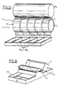
- the device according to the present invention represented in FIG. 2 comprises a rigid support 10 provided with a handling member (grip) 11, on which is mounted a polymer material 20, soaked with development reagent.
- said device is of square shape, with a side of 200 mm, ie of the same dimension as the chromatography plates; the polymeric material has a thickness of 4.5 mm, while the rigid support has a thickness of 20 mm.
- Said device has an inverted T shape in section and is advantageously used for applying the development reagent on a chromatography plate, as described in Example 1 above.
- said device After use, said device is stored in suitable hermetic tanks.
- FIG. 3 shows another embodiment of the device according to the invention in which the part of the rigid support 10 in contact with the polymer support 20 soaked in reagent is slightly domed.
- the device according to the present invention shown in FIG. 4, comprises a rigid support 10 ′ in the form of a roller, provided with a handling axis 11 ′ around which the porous polymeric material 20 ′ is applied, soaked with development reagent, as described in Example 1 above.
- Said device is used in particular in an installation according to the invention, as visible in FIGS. 5, 6 and 7 for applying the development reagent by rolling on a chromatography plate 30.
- a device according to the invention 1 is firstly placed in the impregnation zone A, in position 1a and is thus impregnated with development reagent; then said device is transferred to position 1b, in the draining zone B, in which the possible excess of reagent is drained, before the passage of device 1 in the development zone C, in which said reagent is released from the device and uniformly impregnates the plate to be revealed.
- FIG. 6 represents said installation, with the removable part 50a of the pivoting cover 50, which allows access to the impregnation and revelation areas, open.
- Said cover has two side edges cut into steps, said edges of the cover delimiting the slide 41 of the means 40 with the side walls 60 of the box 2, cut so as to correspond to said edges.
- FIG. 7 represents a perspective view of the installation as described in FIGS. 5 and 6.
- Figures 9 and 10 show sectional views of the installation of Figure 8.
- the reagent tank 80 filled with appropriate reagent, is placed under the roller R1; the porous polymeric strip 72 is fixed in the clamp 12 of the roller R1.
- the porous material 72 follows the shape of the roller. Arriving in the tank 80, it is continuously impregnated with reagent, during each revolution. A rotation can be performed to prepreg the material 72, in order to saturate it with reagent, before the passage of the plate P.
- the revealing plate P is placed so that its stationary phase is in contact with said porous material 72.
- the revealing takes place as the rotation takes place and the excess of reagent upstream of the revealing zone is rejected in the tank 80.
- the excess reagent after revelation is, for its part, reabsorbed by the porous material 72.
- Figure 10 shows more particularly the free end of the strip of porous material 72, and a housing X in which is housed and protected the roller R1.
- FIG. 11 represents a roller R1 comprising, in the example shown, 5 strips (n1 to n5) of porous material 72, separated from each other by grooves r1 to r4, which strips are respectively impregnated in compartments 801 to 805 of the tank with compartmentalized reagent 80.
- This installation thus makes it possible to reveal, on the same chromatographic plate, different chromatograms using, in the embodiment shown, five different developers.
- FIG. 12 shows an embodiment of the installation in which the plate P, placed on a support guided on rails or slides 100, passes under the roller R1, rotating around the fixed axis 71.
- the spacing between the porous material 72 covering said roller and the plate P is determined to cause sufficient pressure to produce the revelation.
- the displacement of the mobile support carrying the plate P is done by pushing or pulling.
- the contact of the plate P on the roller R1 allows the rotation of the latter, and the compression of the porous material 72, the roller R1 remaining securely in place during the passage of the plate P by closing the cover C.
Landscapes
- Physics & Mathematics (AREA)
- Health & Medical Sciences (AREA)
- Life Sciences & Earth Sciences (AREA)
- Chemical & Material Sciences (AREA)
- Analytical Chemistry (AREA)
- Biochemistry (AREA)
- General Health & Medical Sciences (AREA)
- General Physics & Mathematics (AREA)
- Immunology (AREA)
- Pathology (AREA)
- Treatment Of Liquids With Adsorbents In General (AREA)
Abstract
Description
La présente invention est relative à un perfectionnement apporté à l'étape de révélation de la chromatographie en couche mince, à un dispositif de révélation pour la mise en oeuvre dudit perfectionnement ainsi qu'à une installation comportant ledit dispositif.The present invention relates to an improvement made to the stage of revealing thin layer chromatography, to a development device for implementing said improvement as well as to an installation comprising said device.
La chromatographie en couche mince (CCM) est une méthode de séparation par migration différentielle entre une phase stationnaire et une phase mobile. La couche mince présente un certain nombre d'avantages (notamment rapidité de migration, emploi de n'importe quel type de réactif de révélation).Thin layer chromatography (TLC) is a method of separation by differential migration between a stationary phase and a mobile phase. The thin layer has a number of advantages (notably speed of migration, use of any type of development reagent).
C'est une méthode d'identification qui permet notamment de déterminer la pureté d'un produit, les produits de décomposition donnant des tâches supplémentaires.It is an identification method which makes it possible in particular to determine the purity of a product, the decomposition products giving additional tasks.
La CCM présente de nombreuses applications qualitatives tant dans le domaine pharmaceutique que dans le domaine agro-alimentaire. Cependant, la CCM se prête à une interprétation quantitative avec des erreurs de 5 à plus de 10 % dans certains cas.The CCM has many qualitative applications both in the pharmaceutical and in the food industry. However, the CCM is open to quantitative interpretation with errors of 5 to more than 10% in some cases.
La CCM comprend cinq étapes :
- . le dépôt des substances à identifier et/ou à doser sur un support approprié ;
- . la migration ;
- . le séchage ;
- . la révélation ;
- . la lecture.
- . depositing the substances to be identified and / or assayed on an appropriate medium;
- . the migration ;
- . drying ;
- . the revelation ;
- . reading.
Un certain nombre de ces opérations ont été optimisées, afin de diminuer les risques d'erreurs inhérents aux différentes manipulations ; en particulier, les opérations de dépôt, de migration, de séchage et de lecture ont notamment été automatisées et ont permis de diminuer notablement les risques d'erreur ; par contre, la révélation, à l'heure actuelle, lorsqu'elle est nécessaire, est réalisée soit - par pulvérisation de réactifs spécifiques qui permettent d'obtenir des tâches colorées ou fluorescentes, soit - par immersion totale de la plaque de chromatographie.A certain number of these operations have been optimized, in order to reduce the risk of errors inherent in the various manipulations; in particular, the deposit, migration, drying and reading operations have been automated in particular and have significantly reduced the risk of error; on the other hand, revelation, at present, when it is necessary, is carried out either - by spraying specific reagents which make it possible to obtain colored or fluorescent stains, or - by total immersion of the chromatography plate.
Par exemple, l'article aux noms de N. DE KRUIF et al. (J. Chromato., 1987, 410, 395-411) décrit un procédé de détection de conservateurs dans des produits cosmétiques. La procédure plus particulièrement décrite pour cette identification, est une procédure chromatographique en couche mince. Six réactifs de détection sont décrits dont 5 sont pulvérisés et dont le sixième, en raison de sa toxicité, est appliqué sur la plaque chromatographique à l'aide d'un rouleau recouvert de laine, préalablement immergé dans ledit réactif ; il est, en particulier, spécifié que l'application du rouleau est réalisée jusqu'à mouillage complet de la plaque chromatographique.For example, the article in the names of N. DE KRUIF et al. (J. Chromato., 1987, 410 , 395-411) describes a method for detecting preservatives in cosmetic products. The procedure more particularly described for this identification is a thin layer chromatographic procedure. Six detection reagents are described, 5 of which are sprayed and the sixth of which, because of its toxicity, is applied to the chromatographic plate using a roller covered with wool, previously immersed in said reagent; it is, in particular, specified that the application of the roller is carried out until complete wetting of the chromatographic plate.
Ces techniques de révélation par pulvérisation ou immersion présentent un certain nombre d'inconvénients :
En particulier, la pulvérisation :
- donne des résultats différents selon le manipulateur ;
- donne un fond non homogène ;
- peut nécessiter l'utilisation d'air comprimé, et donc d'une installation particulière ;
- peut provoquer des traînées ou coulées qui rendront la lecture difficilement interprétable.
In particular, spraying:
- gives different results depending on the manipulator;
- gives a non-homogeneous background;
- may require the use of compressed air, and therefore of a particular installation;
- may cause streaks or streaks which will make reading difficult to interpret.
La révélation par immersion pour sa part :
- peut provoquer une diffusion et une dilution des taches ;
- donne un fond trop coloré ;
- réclame une quantité importante de révélateur.
- may cause diffusion and dilution of spots;
- gives an overly colored background;
- claims a significant amount of developer.
La présente invention s'est, en conséquence, donné pour but de pourvoir à un perfectionnement de l'étape de révélation de la chromatographie en couche mince, qui répond mieux aux nécessités de la pratique que les procédés de révélation utilisés jusqu'à présent, notamment en ce qu'il a l'avantage d'améliorer, de manière inattendue, la reproductibilité et la répétabilité des techniques de chromatographie en couche mince, plus particulièrement dans leurs applications quantitatives.The object of the present invention is therefore to provide an improvement in the stage of revealing layer chromatography. thin, which responds better to the needs of the practice than the revelation methods used until now, in particular in that it has the advantage of unexpectedly improving the reproducibility and the repeatability of the techniques of layer chromatography thin, especially in their quantitative applications.
C'est également un but de l'invention de pourvoir à un dispositif de révélation pour la mise en oeuvre dudit perfectionnement, ainsi qu'à une installation comportant ledit dispositif.It is also an object of the invention to provide a revelation device for the implementation of said improvement, as well as an installation comprising said device.
La présente invention a pour objet un procédé de révélation en chromatographie en couche mince, comprenant une mise en contact d'une plaque de chromatographie à révéler avec un matériau imprégné d'un réactif de révélation, caractérisé en ce que ladite mise en contact est réalisée en pressant, de manière sensiblement uniforme, un polymère poreux contenant ledit réactif de révélation contre ladite plaque de CCM à révéler, lequel polymère poreux possède (i) un pouvoir absorbant suffisant pour imprégner complètement ladite plaque de chromatographie, sans l'immerger lors de la mise en contact sous pression, et (ii) une capacité de réabsorption de l'excès de réactif, au moment du retrait dudit polymère poreux de ladite plaque.The subject of the present invention is a process for revealing in thin layer chromatography, comprising bringing a chromatography plate to be revealed into contact with a material impregnated with a development reagent, characterized in that said contacting is carried out by pressing, in a substantially uniform manner, a porous polymer containing said developer reagent against said TLC plate to be revealed, which porous polymer has (i) sufficient absorbency to completely impregnate said chromatography plate, without immersing it during the contacting under pressure, and (ii) a capacity for reabsorption of the excess reagent, at the time of the removal of said porous polymer from said plate.
On entend par pression, au sens de la présente invention, l'action de presser ou de pousser avec effort, ladite pression pouvant être exercée manuellement ou mécaniquement.Pressure means, in the sense of the present invention, the action of pressing or pushing with effort, said pressure being able to be exerted manually or mechanically.
Ledit polymère poreux est résistant aux réactifs de révélation usuels de la chromatographie.Said porous polymer is resistant to the usual development reagents for chromatography.
Un tel procédé de révélation appelé dérivatisation sous pression (DSP) par les Inventeurs, a l'avantage de donner un fond uniforme et d'améliorer, de manière inattendue, la reproductibilité et la répétabilité des techniques de chromatographie en couche mince, notamment quantitatives.Such a revelation process called pressure derivatization (DSP) by the Inventors, has the advantage of giving a uniform background and unexpectedly improving the reproducibility and repeatability of thin layer chromatography techniques, especially quantitative.
Un tel procédé a également l'avantage d'être aisément automatisable.Such a method also has the advantage of being easily automated.
La présente invention a également pour objet un dispositif de révélation pour chromatographie en couche mince, caractérisé en ce qu'il comprend :
- un polymère poreux, résistant aux réactifs de révélation usuels de la chromatographie et présentant un pouvoir absorbant suffisant pour imprégner complètement une plaque de chromatographie sans l'immerger au moment de la mise en contact sous pression et pour réabsorber l'excès de réactif lors du retrait de ladite matière poreuse de la plaque de chromatographie, et
- un support de manipulation inerte par rapport aux réactifs de révélation, de rigidité suffisante pour permettre l'application d'une pression appropriée sur la plaque de chromatographie en couche mince et sur lequel est monté ou fixé ladite matière poreuse.
- a porous polymer, resistant to the usual development reagents for chromatography and having sufficient absorbency to completely impregnate a chromatography plate without immersing it when brought into contact under pressure and to reabsorb the excess reagent during removal of said porous material of the chromatography plate, and
- a support for handling inert with respect to the development reagents, of sufficient rigidity to allow the application of an appropriate pressure on the thin layer chromatography plate and on which said porous material is mounted or fixed.
Ledit polymère présente avantageusement une structure de mousse ou d'éponge.Said polymer advantageously has a foam or sponge structure.
Selon une disposition avantageuse de ce mode de réalisation, ledit polymère est une mousse de polyuréthane à alvéoles ouvertes.According to an advantageous arrangement of this embodiment, said polymer is a polyurethane foam with open cells.
Selon un autre mode de réalisation avantageux dudit dispositif, il est de forme cylindrique, par exemple un rouleau ou présente une surface semi-cylindrique convexe.According to another advantageous embodiment of said device, it is of cylindrical shape, for example a roller or has a convex semi-cylindrical surface.
Selon encore un autre mode de réalisation avantageux dudit dispositif, il est de forme rectangulaire.According to yet another advantageous embodiment of said device, it is rectangular in shape.
Ledit dispositif présente nécessairement une zone de contact plan avec la plaque de chromatographie, pour appliquer une pression sensiblement constante et uniforme sur la plaque de chromatographie, quelle que soit la zone de contact.Said device necessarily has a planar contact zone with the chromatography plate, in order to apply a substantially constant and uniform pressure on the chromatography plate, whatever the contact zone.
La présente invention a, en outre, pour objet une installation appropriée à l'étape de révélation de la chromatographie en couche mince, caractérisée en ce qu'elle comprend, outre un dispositif conforme à l'invention, des moyens de guidage et de déplacement dudit dispositif et/ou de la plaque de chromatographie à révéler.The present invention further relates to an installation suitable for the stage of revealing thin layer chromatography, characterized in that it comprises, in addition to a device according to the invention, means for guiding and moving of said device and / or of the chromatography plate to be revealed.
Selon un mode de réalisation avantageux de ladite installation, lorsqu'elle comprend des moyens de guidage et de déplacement du dispositif, elle comprend en outre :
- une zone d'imprégnation du dispositif de révélation conforme à l'invention ;
- une zone de révélation où se trouve la plaque de chromatographie en couche mince à révéler ; et lesdits moyens de guidage déplacent ledit dispositif entre une position où il se trouve dans la zone d'imprégnation et une position de repos, lequel déplacement provoque la mise sous pression du dispositif conforme à l'invention avec la plaque de chromatographie en couche mince et l'imprégnation de ladite plaque par le réactif de révélation.
- an impregnation zone of the revealing device according to the invention;
- a development area where the thin layer chromatography plate to be found is located; and said guide means move said device between a position where it is in the impregnation zone and a rest position, which displacement causes the device according to the invention to be pressurized with the thin layer chromatography plate and the impregnation of said plate with the development reagent.
Selon une disposition avantageuse de ce mode de réalisation, ladite installation comprend en outre une zone d'égouttage du dispositif, entre la zone d'imprégnation et la zone de révélation.According to an advantageous arrangement of this embodiment, said installation also comprises a zone for draining the device, between the impregnation zone and the revelation zone.
Conformément à ce mode de `réalisation, ledit dispositif est avantageusement un rouleau de forme cylindrique, comprenant un arbre axial dont les extrémités sont reçues dans des glissières de guidage s'étendant latéralement de part et d'autre des zones précitées d'imprégnation, de révélation et de repos.According to this embodiment, said device is advantageously a roller of cylindrical shape, comprising an axial shaft whose ends are received in guide rails extending laterally on either side of the aforementioned impregnation zones, revelation and rest.
Selon une autre disposition avantageuse de ce mode de réalisation, ladite installation se présente sous la forme d'une boîte à couvercle pivotant, permettant l'accès aux zones précitées d'imprégnation, de révélation et de repos et délimitant les glissiéres précitées avec les parois latérales fixes de ladite boîte.According to another advantageous arrangement of this embodiment, said installation is in the form of a box with pivoting cover, allowing access to the aforementioned areas of impregnation, revelation and rest and delimiting the aforementioned slides with the walls fixed sides of said box.
Selon un autre mode de réalisation avantageux de ladite installation, lorsqu'elle comprend des moyens de guidage et de déplacement de la plaque de chromatographie à révéler, ledit dispositif comprend un rouleau cylindrique monté en rotation autour d'un axe fixe et sur la surface cylindrique duquel est enroulée ladite matière poreuse imprégnée desdits réactifs et lesdits moyens de guidage déplacent ladite plaque de chromatographie -située à une distance dudit rouleau cylindrique choisie pour assurer une pression de contact déterminée de la matière poreuse sur la plaque et pour réaliser l'imprégnation de ladite plaque par le réactif de révélation-, dans un plan tangentiel audit rouleau.According to another advantageous embodiment of said installation, when it includes means for guiding and moving the chromatography plate to be revealed, said device comprises a cylindrical roller mounted for rotation about a fixed axis and on the cylindrical surface of which is wound said porous material impregnated with said reagents and said guide means move said chromatography plate -located at a distance from said cylindrical roller chosen to ensure a determined contact pressure of the porous material on the plate and to effect the impregnation of said plate by the development reagent, in a plane tangential to said roller.
Selon une disposition avantageuse de ce mode de réalisation, les moyens de guidage de la plaque de chromatographie à révéler sont constitués par un deuxième rouleau, tournant autour d'un axe fixe, parallèle à celui du premier rouleau et verticalement écarté de celui-ci.According to an advantageous arrangement of this embodiment, the means for guiding the chromatography plate to be revealed are constituted by a second roller, rotating around a fixed axis, parallel to that of the first roller and vertically spaced from the latter.
Selon une modalité avantageuse de cette disposition, au moins l'un des deux rouleaux est entraîné en rotation autour de son axe.According to an advantageous modality of this arrangement, at least one of the two rollers is driven in rotation about its axis.
Le deuxième rouleau a l'avantage à la fois de coopérer avec le premier rouleau dans le guidage de ladite plaque de chromatographie et de permettre l'application d'une pression uniforme et homogène, exercée par le dispositif de révélation de forme cylindrique ou rouleau sur la plaque à révéler.The second roller has the advantage both of cooperating with the first roller in guiding said chromatography plate and of allowing the application of a uniform and homogeneous pressure, exerted by the revealing device of cylindrical shape or roller on the plaque to reveal.
Selon une autre disposition avantageuse de ce mode de réalisation, ladite installation comprend une zone d'imprégnation en réactif, située sous le premier rouleau.According to another advantageous arrangement of this embodiment, said installation comprises a reagent impregnation zone, located under the first roller.
Selon encore une autre disposition avantageuse de ce mode de réalisation de l'installation, la surface cylindrique du premier rouleau est partagée en plusieurs compartiments ou secteurs, juxtaposés le long de l'axe du rouleau.According to yet another advantageous arrangement of this embodiment of the installation, the cylindrical surface of the first roller is divided into several compartments or sectors, juxtaposed along the axis of the roller.
Ladite zone d'imprégnation peut avantageusement être compartimentée de la même façon que le rouleau.Said impregnation zone can advantageously be compartmentalized in the same way as the roller.
Une telle zone a l'avantage de permettre, sur une même plaque, la révélation de différents chromatogrammes, à l'aide de 2 à n révélateurs situés dans les différents compartiments dudit bac à compartiments.Such a zone has the advantage of allowing, on the same plate, the revealing of different chromatograms, using 2 to n developers located in the different compartments of said compartment bin.
Selon encore une autre disposition de ce mode de réalisation, les moyens de guidage de la plaque de chromatographie sont constitués par des glissières orientées dans le plan précité perpendiculairement à l'axe du dispositif, recevant les bords de ladite plaque de révélation ou de son support, et des moyens de traction ou de poussée sont prévus pour déplacer ladite plaque le long des glissières.According to yet another arrangement of this embodiment, the means for guiding the chromatography plate consist of slides oriented in the above-mentioned plane perpendicular to the axis of the device, receiving the edges of said revelation plate or of its support. , and traction or pushing means are provided for moving said plate along the slides.
Selon une modalité avantageuse de cette disposition, lesdites glissières sont des rainures ou des rails montés sur un boîtier de support dudit premier rouleau cité.According to an advantageous modality of this arrangement, said slides are grooves or rails mounted on a support housing of said first cited roller.
Outre les dispositions qui précèdent, l'invention comporte encore d'autres dispositions, qui ressortiront de la description qui va suivre.In addition to the foregoing provisions, the invention also comprises other provisions, which will emerge from the description which follows.
L'invention sera mieux comprise à l'aide du complément de description qui va suivre, qui se réfère à des exemples de mise en oeuvre du procédé conforme à l'invention et à une description détaillée du dispositif de révélation et de l'installation selon l'invention, avec référence aux dessins annexés dans lesquels :
- la figure 1 représente une courbe d'étalonnage du procédé conforme à l'invention ;
- la figure 2 est une représentation en perspective d'un mode de réalisation de forme carrée du dispositif conforme à la présente invention ;
- la figure 3 est une représentation d'un autre mode de réalisation carré du dispositif conforme à l'invention ;
- la figure 4 est une représentation d'un mode de réalisation cylindrique du dispositif conforme à l'invention ;
- les figures 5, 6 et 7 sont une représentation d'un mode de réalisation de l'installation conforme à l'invention : les figures 5 et 6 sont des vues en coupe et la figure 7 est une vue en perspective ;
- la figure 8 est une représentation en perspective d'un mode de réalisation d'une installation conforme à l'invention, comprenant un dispositif de révélation cylindrique et dont les moyens de guidage de la plaque de chromatographie à révéler sont représentés par un second rouleau ;
- les figures 9 et 10 sont des vues en coupe de l'installation de la figure 8 ;
- la figure 11 est une représentation en perspective d'un autre mode de réalisation d'une installation conforme à l'invention, comprenant un dispositif de révélation cylindrique et dont les moyens de guidage de la plaque de chromatographie à révéler sont constitués par un second rouleau ;
- la figure 12 est une représentation en perspective d'un mode de réalisation d'une installation conforme à l'invention, comprenant un dispositif de révélation cylindrique et dont les moyens de guidage de la plaque de chromatographie à révéler sont constitués par des rails, recevant les bords d'un support de ladite plaque de révélation et associés à des moyens de traction de ladite plaque le long desdits rails.
- FIG. 1 represents a calibration curve of the method according to the invention;
- Figure 2 is a perspective representation of an embodiment of the device according to the present invention in square form;
- Figure 3 is a representation of another square embodiment of the device according to the invention;
- Figure 4 is a representation of a cylindrical embodiment of the device according to the invention;
- Figures 5, 6 and 7 are a representation of an embodiment of the installation according to the invention: Figures 5 and 6 are sectional views and Figure 7 is a perspective view;
- FIG. 8 is a perspective representation of an embodiment of an installation according to the invention, comprising a cylindrical revealing device and the means for guiding the chromatography plate to be revealed are represented by a second roller;
- Figures 9 and 10 are sectional views of the installation of Figure 8;
- FIG. 11 is a perspective representation of another embodiment of an installation according to the invention, comprising a cylindrical development device and the means for guiding the chromatography plate to be revealed are constituted by a second roller ;
- Figure 12 is a perspective representation of an embodiment of an installation according to the invention, comprising a cylindrical revealing device and whose guide means of the chromatography plate to be revealed are constituted by rails, receiving the edges of a support of said revelation plate and associated with means for pulling said plate along said rails.
Il doit être bien entendu, toutefois, que ces dessins et les parties descriptives correspondantes ainsi que les exemples sont donnés uniquement à titre d'illustration de l'objet de l'invention, dont ils ne constituent en aucune manière une limitation.It should be understood, however, that these drawings and the corresponding descriptive parts as well as the examples are given solely by way of illustration of the subject of the invention, of which they do not in any way constitute a limitation.
On réalise une chromatographie sur couche mince pour le dosage du tryptophane comme suit :
- plaques : cellulose non fluorescente 20 x 20 cm (MERCK)
- phase mobile :
- échantillons : solution de tryptophane à 2 mg/ml
- dépôts : 10 dépôts de 2 µl, réalisés à l'aide de l'appareil LINOMAT IV (CAMAG)
- réactif de révélation : ninhydrine/cuivre
solution A :
solution B : nitrate cuivrique à 2 % dans l'éthanol
On mélange 100 ml de solution A et 6 ml de solution B, pour obtenir le réactif de révélation.
- on imbibe un dispositif de révélation conforme à l'invention avec le réactif de révélation ci-dessus ;
- on applique ledit dispositif imbibé sous pression sur la plaque de chromatographie, au moment de la révélation ;
- la lecture photodensitométrique est réalisée à l'aide d'un appareil CD60 (DESAGA). Les plaques sont lues avant et après révélation à l'aide du dispositif conforme à l'invention.
1. Chromatogramme non révélé - lecture à 254 nm (U.V. direct) :
2. Chromatogramme après révélation à la ninhydrine par le dispositif de révélation sous pression - lecture à 510 nm :
- plates: non-fluorescent cellulose 20 x 20 cm (MERCK)
- mobile phase:
- samples:
- deposits: 10 deposits of 2 µl, made using the LINOMAT IV device (CAMAG)
- development reagent: ninhydrin / copper
solution A:
solution B: 2% cupric nitrate in ethanol
100 ml of solution A and 6 ml of solution B are mixed to obtain the development reagent.
- a development device in accordance with the invention is soaked with the above development reagent;
- applying said device soaked under pressure on the chromatography plate, at the time of development;
- photodensitometric reading is carried out using a CD60 device (DESAGA). The plates are read before and after revelation using the device according to the invention.
1. Chromatogram not revealed - reading at 254 nm (direct UV ):
2. Chromatogram after revelation with ninhydrin by the pressure revelation device - reading at 510 nm :
Les résultats obtenus dans l'exemple 1 sont comparés à ceux obtenus lorsque, dans les mêmes conditions, la révélation est réalisée par pulvérisation.
1. Chromatogramme non révélé - lecture à 254 nm (U.V. direct) :
2. Chromatogramme après révélation à la ninhydrine par pulvérisation classique - lecture à 510 nm :
1. Chromatogram not revealed - reading at 254 nm (direct UV) :
2. Chromatogram after revelation with ninhydrin by conventional spraying - reading at 510 nm :
10 dépôts de 4 µl de solutions de tryptophane à : 0,1 mg/ml, 0,2 mg/ml, 0,5 mg/ml, 1 mg/ml et 2 mg/ml ont été déposés sur une plaque de chromatographie en couche mince en cellulose 20 x 20 (sans fluorescence), (MERCK DARMSTADT, R.F.A.).10 deposits of 4 μl of tryptophan solutions at: 0.1 mg / ml, 0.2 mg / ml, 0.5 mg / ml, 1 mg / ml and 2 mg / ml were deposited on a chromatography plate in 20 x 20 thin cellulose layer (without fluorescence), (MERCK DARMSTADT, RFA).
Les lectures ont été effectuées avant révélation à 275 nm et après révélation par la ninhydrine à 288 nm. La révélation est faite d'une part, par spray et d'autre part à l'aide de la DSP (dérivation sous pression conforme à l'invention).The readings were taken before revelation at 275 nm and after revelation with ninhydrin at 288 nm. The revelation is made on the one hand, by spray and on the other hand using the DSP (pressure diversion according to the invention).
Comme le montre les courbes d'étalonnages (figure 1), il y a similitude entre la lecture en UV. direct (courbe 2) et la dérivation sous pression (courbe 1,) contrairement à la révélation par spray (courbe 3), qui devient linéaire.
Les équations desdites courbes sont les suivantes :
- UV direct à 275 nm (courbe 2)
- : Y = 0,041 x 100,0118 X r = 0,9958
- DSP à 288 nm (courbe 1)
- : Y = 0,047 x 100,0021 X r = 0,9972
- Spray à 288 nm (courbe 3)
- : Y = 0,0095 X -8,5226 r = 0,9946
The equations of said curves are as follows:
- Direct UV at 275 nm (curve 2)
- : Y = 0.041 x 10 0.0118 X r = 0.9958
- DSP at 288 nm (curve 1)
- : Y = 0.047 x 10 0.0021 X r = 0.9972
- Spray at 288 nm (curve 3)
- : Y = 0.0095 X -8.5226 r = 0.9946
Des solutions test contenant 9 vitamines hydrosolubles ont été préparées selon des concentrations croissantes.Test solutions containing 9 water-soluble vitamins were prepared in increasing concentrations.
Une première solution a été établie comme suit :
Les autres solutions correspondent à une dilution au demi et au quart de la solution ci-dessus.The other solutions correspond to a dilution of half and a quarter of the above solution.
10 dépôts de 10 µl de ces solutions ont été appliqués sur des plaques silice HPTLC - 60 F 254 - 20 x 20 (Merck Darmstadt - RFA) à 2 cm du bord de la plaque. La migration se fait par OPLC, selon les conditions suivantes :
Débit : 0,2 ml/min développement : 16 cm
Pression de la pompe à eau : 25 bars
Pression de la pompe à éluant : 4 bars
Pre-rum à l'hexane.10 deposits of 10 µl of these solutions were applied to silica plates HPTLC - 60 F 254 - 20 x 20 (Merck Darmstadt - RFA) 2 cm from the edge of the plate. The migration is done by OPLC, under the following conditions:
Flow rate: 0.2 ml / min development: 16 cm
Water pump pressure: 25 bars
Eluent pump pressure: 4 bars
Pre-rum with hexane.
La plaque est séchée à l'air, la lecture est réalisée en UV direct à 254 nm pour les vitamines B₁, B₂, C, et la niacinamide, puis à 290 nm pour l'acide folique et la vitamine B₆.The plate is air-dried, the reading is carried out in direct UV at 254 nm for vitamins B₁, B₂, C, and niacinamide, then at 290 nm for folic acid and vitamin B₆.
La vitamine B₁₂ et la biotine sont enregistrées à 530 nm après DSP par une solution à 0,1 % (p/v) de 4-diméthyl amine-cinnamaldéhyde et 1 % (v/v) d'acide sulfurique dans l'éthanol.Vitamin B₁₂ and biotin are recorded at 530 nm after DSP by a 0.1% (w / v) solution of 4-dimethyl amine-cinnamaldehyde and 1% (v / v) of sulfuric acid in ethanol.
Le pantothénate de calcium est lu à 375 nm après DSP, par la ninhydrine.The calcium pantothenate is read at 375 nm after DSP, by ninhydrin.
La quantification est réalisée par lecture densitométrique en réflexion, à l'aide des surfaces des pics obtenus, comme le montre le Tableau ci-après :
Les plaques de chromatographie en couche mince en cellulose 10 x 10 (sans fluorescence) (Merck-Darmstadt-RFA) ont été révélées par du dragendorff à l'aide de la dérivation sous pression, conforme à l'invention sur une surface de 5 x 10 cm. Le polymère de 4,5 mm d'épaisseur utilisé a été comprimé pendant 5 secondes à l'aide de poids de 500 g, 1 000 g, 2 000 g et 5 000 g ainsi qu'une révélation sans pression correspondant à une simple apposition du polymére sur la plaque.The 10 x 10 cellulose thin layer chromatography plates (without fluorescence) (Merck-Darmstadt-RFA) were revealed by dragendorff using the pressure diversion, in accordance with the invention, on a surface of 5 x 10 cm. The 4.5 mm thick polymer used was compressed for 5 seconds using weights of 500 g, 1,000 g, 2,000 g and 5,000 g as well as a pressureless revelation corresponding to a simple affixing of polymer on the plate.
Une lecture densitométrique du bruit de fond obtenu a été réalisée ; la longueur d'onde utilisée est de 350 nm, maximum d'absorption du dragendorff. Le zéro est obtenu sur la partie non révélée de la plaque.
A une pression appliquée sur le polymère correspond une aspiration du réactif lors du relâchement de cette pression. Celle-ci est très importante lors des applications des poids de 1 000 g et 2 000 g/50 cm2 et provoque un retour du révélateur au sein du polymère. Ce retour est négligeable pour 5 000 g/50 cm2 ou plus et inexistant pour une pression de 500 g/50 cm2.A pressure applied to the polymer corresponds to an aspiration of the reagent when this pressure is released. This is very important during applications of the weights of 1000 g and 2000 g / 50 cm2 and causes the developer to return to the polymer. This return is negligible for 5,000 g / 50 cm2 or more and nonexistent for a pressure of 500 g / 50 cm2.
L'absence de pression provoque une simple diffusion du réactif vers la plaque de façon très inhomogène.The absence of pressure causes a simple diffusion of the reagent towards the plate in a very inhomogeneous way.
La révélation optimum est obtenue à l'aide d'une pression de 5 000 g/50 cm2 soit 40 kg pour une plaque standard de 20 x 20 cm pour un polymère de 4,5 mm d'épaisseur.The optimum development is obtained using a pressure of 5,000 g / 50
Le procédé conforme à l'invention peut notamment être mise en oeuvre à l'aide de l'un des dispositifs décrits ci-après.The method according to the invention can in particular be implemented using one of the devices described below.
Le dispositif conforme à la présente invention, représenté à la figure 2 comprend un support rigide 10 muni d'un organe de manipulation (préhension) 11, sur lequel est montée une matière en polymère 20, imbibée de réactif de révélation. Dans cette réalisation, et ce, de manière non limitative, ledit dispositif est de forme carrée, de côté de 200 mm, c'est à dire de même dimension que les plaques de chromatographie ; la matière polymérique présente une épaisseur de 4,5 mm, alors que le support rigide à une épaisseur de 20 mm.The device according to the present invention, represented in FIG. 2 comprises a
Ledit dispositif présente en coupe une forme en T inversé et est avantageusement utilisé pour appliquer le réactif de révélation sur une plaque de chromatographie, comme décrit dans l'exemple 1 ci-dessus.Said device has an inverted T shape in section and is advantageously used for applying the development reagent on a chromatography plate, as described in Example 1 above.
Après utilisation, ledit dispositif est stocké dans des cuves hermétiques appropriées.After use, said device is stored in suitable hermetic tanks.
La figure 3 représente un autre mode de réalisation du dispositif conforme à l'invention dans lequel la partie du support rigide 10 en contact avec le support polymérique 20 imbibé de réactif est légèrement bombé.FIG. 3 shows another embodiment of the device according to the invention in which the part of the
Le dispositif conforme à la présente invention, représenté à la figure 4 comprend un support rigide 10' en forme de rouleau, muni d'un axe de manipulation 11' autour duquel est appliquée la matière poreuse polymérique 20', imbibée de réactif de révélation, comme décrit dans l'exemple 1 ci-dessus.The device according to the present invention, shown in FIG. 4, comprises a
Ledit dispositif est notamment utilisé dans une installation conforme à l'invention, comme visible sur les figures 5, 6 et 7 pour appliquer le réactif de révélation par roulement sur une plaque de chromatographie 30.Said device is used in particular in an installation according to the invention, as visible in FIGS. 5, 6 and 7 for applying the development reagent by rolling on a
La figure 5 représente un mode de réalisation d'une installation conforme à l'invention sous la forme d'une boîte 2, qui comprend :
- une zone d'imprégnation A du dispositif 1, représentée dans cette installation par un bac dans lequel se trouve un réactif de révélation, comme décrit dans l'exemple 1 ;
- une zone de révélation C, où se trouve la plaque de chromatographie 30 à révéler et qui comprend également les supports de plaque 31₁
et 31₂ ainsi que les butées 32₁ et 32₂, qui bloquent ladite plaque ; - des moyens de guidage et de déplacement 40 du dispositif 1 entre une position la où il se trouve dans la zone d'imprégnation et une position 1d dite de repos (zone D) ; les extrémités de l'axe 11' dudit dispositif sont ainsi reçues dans les glissières 41 du moyen 40 s'étendant au dessus de la plaque de chromatographie 30 ;
- une zone d'égouttage B du dispositif 1 (
position 1b dudit dispositif), située entre la zone d'imprégnation A et la zone de révélation C.
- an impregnation zone A of the
device 1, represented in this installation by a tank in which there is a development reagent, as described in Example 1; - a revelation zone C, where the
chromatography plate 30 to be revealed is located and which also includes the plate supports 31₁ and 31₂ as well as the stops 32₁ and 32₂, which block said plate; - means for guiding and moving the
device 1 between a position 1a where it is in the impregnation zone and a position 1d called rest (zone D); the ends of the axis 11 'of said device are thus received in the slides 41 of themeans 40 extending above thechromatography plate 30; - a drip zone B of the device 1 (
position 1b of said device), located between the impregnation zone A and the revelation zone C.
Une telle installation permet l'application d'une pression constante et uniforme sur ladite plaque 30 et permet de ce fait l'obtention d'une révélation nettement améliorée, comme montré aux exemples 1 et 2 ci-dessus.Such an installation allows the application of a constant and uniform pressure on said
Un dispositif conforme à l'invention 1 est tout d'abord placé dans la zone d'imprégnation A, en position 1a et est ainsi imprégné de réactif de révélation ; puis ledit dispositif est transféré en position 1b, dans la zone d'égouttage B, dans laquelle l'éventuel excédent de réactif est égoutté, avant le passage du dispositif 1 dans la zone de révélation C, dans laquelle ledit réactif est libéré du dispositif et imprègne uniformément la plaque à révéler.A device according to the
La figure 6 représente ladite installation, avec la partie amovible 50a du couvercle 50 pivotant, qui permet l'accès aux zones d'imprégnation et de révélation, ouverte. Ledit couvercle présente deux rebords latéraux découpés en gradins, lesdits rebords du couvercle délimitant les glissière 41 du moyen 40 avec les parois 60 latérales de la boîte 2, découpées de façon à correspondre auxdits rebords.FIG. 6 represents said installation, with the
La figure 7 représente une vue en perspective de l'installation telle que décrite aux figures 5 et 6.FIG. 7 represents a perspective view of the installation as described in FIGS. 5 and 6.
La partie de l'installation représentée à la figure 8 comprend :
- . un dispositif de révélation formé d'un rouleau R₁ qui comprend un support rigide 70 de forme cylindrique tournant autour d'un axe de rotation fixe 71 et sur la surface duquel est appliquée une bande 72 de matière poreuse polymérique, imbibée de réactif de révélation, comme décrit dans l'exemple 1 ci-dessus. Le rouleau R₁ comporte un moyen de fixation de la matière poreuse polymérique 72, formé par exemple par une
pince 73 placée le long d'une génératrice du rouleau, et encastrée dans celui-ci pour ne pas faire saillie au-dessus de la surface cylindrique du rouleau, cette pince permettant de fixer ladite matière poreuse 72 par une de ses extrémités, l'autre extrémité restant libre. Le rouleau R₁ tourne autour de l'axe fixe 71 dans le sens des aiguilles d'une montre en figure 1, en étant entraîné en rotation par tout moyen approprié, notamment un moyen mécanique tel qu'une manivelle ou bien un moteur ; - . un bac à réactif 80, éventuellement extractible, situé sous le rouleau R₁ ;
- . un rouleau R₂ tournant autour d'un axe fixe 91, parallèle à celui du rouleau R₁ et verticalement écarté de celui-ci ; ce rouleau R₂ est entraîné à l'aide de moyens appropriés et notamment, de manière non limitative, à l'aide d'engrenages, lors de la rotation du cylindre R₁, dans le sens opposé à ce dernier et à une vitesse identique.
- . la plaque de chromatographie à révéler P, comme visible sur les figures 2
et 3, qui est prise en sandwich entre les rouleaux R₁ et R₂. La plaque est entraînée par les deux rouleaux et déplacée en contact avec la matière poreuse, sous une pression déterminée en fonction de l'épaisseur de la plaque P, de l'épaisseur de la matière poreuse et de la distance entre les deux rouleaux.
- . a revealing device formed by a roller R₁ which comprises a
rigid support 70 of cylindrical shape rotating around a fixed axis ofrotation 71 and on the surface of which is applied astrip 72 of polymeric porous material, soaked in developer reagent, as described in Example 1 above. The roller R₁ comprises a means for fixing the porouspolymeric material 72, formed for example by aclamp 73 placed along a generatrix of the roller, and embedded in the latter so as not to protrude above the cylindrical surface of the roller, this clamp making it possible to fix saidporous material 72 by one of its ends, the other end remaining free. The roller R₁ rotates around the fixedaxis 71 in a clockwise direction in FIG. 1, being driven in rotation by any suitable means, in particular a mechanical means such as a crank or else a motor; - . a
reagent tank 80, optionally extractable, located under the roller R₁; - . a roller R₂ rotating about a fixed
axis 91, parallel to that of the roller R₁ and vertically spaced therefrom; this roller R₂ is driven using appropriate means and in particular, without limitation, using gears, during the rotation of the cylinder R₁, in the opposite direction to the latter and at an identical speed. - . the chromatography plate to be revealed P, as visible in FIGS. 2 and 3, which is sandwiched between the rollers R₁ and R₂. The plate is driven by the two rollers and moved in contact with the porous material, under a pressure determined as a function of the thickness of the plate P, the thickness of the porous material and the distance between the two rollers.
Les figures 9 et 10 montrent des vues en coupe de l'installation de la figure 8. Le bac à réactif 80, rempli de réactif approprié, est placé sous le rouleau R₁ ; la bande poreuse polymérique 72 est fixée dans la pince 12 du rouleau R₁. Lors de la première rotation du rouleau R₁, la matière poreuse 72 épouse la forme du rouleau. En arrivant dans le bac 80, elle est imprégnée de réactif de façon continue, lors de chaque tour. Une rotation peut être effectuée pour pré-imprégner la matière 72, afin de la saturer en réactif, avant le passage de la plaque P.Figures 9 and 10 show sectional views of the installation of Figure 8. The
La plaque à révéler P est placée de manière à ce que sa phase stationnaire soit en contact avec ladite matière poreuse 72. La révélation se fait au fur et à mesure de la rotation et l'excès de réactif en amont de la zone de révélation est rejeté dans le bac 80. L'excès de réactif après révélation est, pour sa part, réabsorbé par la matière poreuse 72.The revealing plate P is placed so that its stationary phase is in contact with said
La figure 10 montre plus particulièrement l'extrémité libre de la bande de matière poreuse 72, et un boîtier X dans lequel est logé et protégé le rouleau R₁.Figure 10 shows more particularly the free end of the strip of
La figure 11 représente un rouleau R₁ comprenant, dans l'exemple représenté, 5 bandes (n₁ à n₅) de matière poreuse 72, séparées entre elles par des rainures r₁ à r₄, lesquelles bandes sont respectivement imprégnées dans des compartiments 80₁ à 80₅ du bac à réactif 80 compartimenté. Cette installation permet ainsi de révéler sur une même plaque chromatographique, différents chromatogrammes à l'aide, dans la réalisation représentée, de cinq révélateurs différents.FIG. 11 represents a roller R₁ comprising, in the example shown, 5 strips (n₁ to n₅) of
La figure 12 montre un mode de réalisation de l'installation dans lequel la plaque P, placée sur un support guidé sur des rails ou glissières 100, passe sous le rouleau R₁, tournant autour de l'axe fixe 71. L'écartement entre la matière poreuse 72 recouvrant ledit rouleau et la plaque P est déterminé pour provoquer une pression suffisante à la réalisation de la révélation. Le déplacement du support mobile portant la plaque P se fait par poussée ou traction. On peut pour cela utiliser tout moyen approprié de déplacement du support, ou utiliser un convoyeur à bande formant ce support. Le contact de la plaque P sur le rouleau R₁ permet la rotation de celui-ci, et la compression de la matière poreuse 72, le rouleau R₁ restant bien en place lors du passage de la plaque P grâce à la fermeture du capot C.FIG. 12 shows an embodiment of the installation in which the plate P, placed on a support guided on rails or slides 100, passes under the roller R₁, rotating around the fixed
Ainsi que cela ressort de ce qui précède, l'invention ne se limite nullement à ceux de ses modes de mise en oeuvre, de réalisation et d'application qui viennent d'être décrits de façon plus explicite ; elle en embrasse au contraire toutes les variantes qui peuvent venir à l'esprit du technicien en la matière, sans s'écarter du cadre, ni de la portée, de la présente invention.As is apparent from the above, the invention is in no way limited to those of its modes of implementation, embodiment and application which have just been described more explicitly; on the contrary, it embraces all the variants which may come to the mind of the technician in the matter, without departing from the framework, or the scope, of the present invention.
Claims (17)
- Developing process using thin-layer chromatography, comprising bringing a chromatographic plate (P) to be developed into contact with a material impregnated with a developing reagent, characterized in that the said contact is brought about by pressing, in substantially uniform manner, a porous polymer (20, 20', 72) containing said developing reagent, against the said TLC plate to be developed, this porous polymer possessing (i) sufficient absorbing power to completely impregnate the said chromatographic plate without immersing it during the contact under pressure, and (ii) a capacity for reabsorbing the excess reagent when the said porous polymer is withdrawn from the said plate.
- Developing device for thin-layer chromatography, characterized in that it comprises:- a porous polymer (20, 20'; 72) which is resistant to conventional developing reagents of chromatography and which has sufficient absorbing power to completely impregnate a chromatographic plate (P) without immersing it at the time of contact under pressure and to reabsorb the excess reagent when the said porous material is withdrawn from the chromatographic plate, and- a manipulation support (10, 11; 10', 11'; 70) which is inert with respect to the developing reagents, has sufficient rigidity to allow an appropriate pressure to be applied to the thin-layer chromatographic plate (P) and on which the said porous material is mounted or fixed.
- Device according to Claim 2, characterized in that the said polymer is an open-cell polyurethane foam.
- Device according to Claim 2 or Claim 3, characterized in that it is cylindrical in shape, for example a roll, or has a semi-cylindrical convex surface.
- Device according to any one of Claims 2 to 4, characterized in that it is rectangular in shape.
- Arrangement suitable for the step of developing in thin-layer chromatography, characterized in that it comprises, in addition to a device according to any one of Claims 2 to 5, means for guiding and displacing the said device (40) and/or the chromatographic plate to be developed (R₂, 100).
- Arrangement according to Claim 6, characterized in that if it comprises means for guiding and displacing the device, it furthermore comprises:- a zone (A) for impregnating the developing device (1) according to any one of Claims 2 to 5;- a developing zone (C) in which the thin-layer chromatographic plate (30) to be developed is located; andthe said guiding means (40) displace the said device between a position in which it is located in the impregnation zone and a rest position (1b), this displacement causing the pressurization of the device according to any one of Claims 2 to 5 with the thin-layer chromatographic plate and the impregnation of the said plate by the developing reagent.
- Arrangement according to Claim 6 or Claim 7, characterized in that it further comprises a zone (B) for dewatering the device, between the impregnation zone and the developing zone.
- Arrangement according to Claim 7 or Claim 8, characterized in that the said device is advantageously a roll which is cylindrical in shape, comprising an axial shaft whereof the ends are received in guiding slides (41) which extend laterally on either side of the above-mentioned impregnation, developing and rest zones.
- Arrangement according to any one of Claims 6 to 9, characterized in that it is in the form of a box (2) having a lid (50) whereof the pivoting part (50a) allows access to the above-mentioned impregnation, developing and rest zones, delimiting the above-mentioned slides with the fixed lateral walls (60) of the said box (2).
- Arrangement according to Claim 6, characterized in that, if it comprises means (R₂, 100) for guiding and displacing the chromatographic plate to be developed, the said device comprises a cylindrical roll (R₁) mounted rotatably about a fixed axis (71) and on the cylindrical surface of which there is rolled the said porous material (72) impregnated with the said reagents and the said guiding means displace the said chromatographic plate (P) - located at a spacing from the said cylindrical roll which is selected to ensure a predetermined contact pressure of the porous material against the plate and to bring about impregnation of the said plate by the developing reagent - in a plane tangential to the said roll.
- Arrangement according to Claim 11, characterized in that the means (R₂, 100) for guiding the said chromatographic plate to be developed are formed by a second roll (R₂) rotating about a fixed axis (91) parallel to that of the first roll and vertically spaced therefrom.
- Arrangement according to Claim 12, characterized in that at least one of the two rolls is driven in rotation about its axis.
- Arrangement according to Claim 12 or Claim 13, characterized in that it comprises a zone (80) for impregnation with reagent, located below the first roll.
- Arrangement according to any one of Claims 12 to 14, characterized in that the cylindrical surface of the first roll is divided into a plurality of compartments or sectors which are placed side by side along the axis of the roll.
- Arrangement according to any one of Claims 12 to 15, characterized in that the means for guiding the chromatographic plate are formed by slides (100) which are oriented in the above-mentioned plane perpendicularly to the axis of the device, receiving the edges of the said developing plate or of its support, and pulling or pushing means are provided to displace the said plate along the slides.
- Arrangement according to Claim 16, characterized in that the said slides are grooves or rails mounted on a support casing of the said first roll mentioned.
Priority Applications (1)
| Application Number | Priority Date | Filing Date | Title |
|---|---|---|---|
| AT9090910753T ATE104771T1 (en) | 1989-07-13 | 1990-07-11 | DEVICE AND INSTALLATION OF THIN LAYER CHROMATOGRAPHY WITH DEVELOPMENT PERFECTION. |
Applications Claiming Priority (5)
| Application Number | Priority Date | Filing Date | Title |
|---|---|---|---|
| FR8909527A FR2649796B1 (en) | 1989-07-13 | 1989-07-13 | IMPROVEMENT FOR THE DEVELOPMENT OF THIN-LAYER CHROMATOGRAPHY, DEVELOPMENT DEVICE AND INSTALLATION COMPRISING SAID DEVICE |
| FR8909527 | 1989-07-13 | ||
| FR9001735A FR2658299B2 (en) | 1989-07-13 | 1990-02-14 | INSTALLATION COMPRISING A REVELATION DEVICE FOR THIN LAYER CHROMATOGRAPHY. |
| FR9001735 | 1990-02-14 | ||
| PCT/FR1990/000520 WO1991001000A1 (en) | 1989-07-13 | 1990-07-11 | Device and installation of thin film chromatography, with improved development |
Publications (2)
| Publication Number | Publication Date |
|---|---|
| EP0435990A1 EP0435990A1 (en) | 1991-07-10 |
| EP0435990B1 true EP0435990B1 (en) | 1994-04-20 |
Family
ID=26227477
Family Applications (1)
| Application Number | Title | Priority Date | Filing Date |
|---|---|---|---|
| EP90910753A Expired - Lifetime EP0435990B1 (en) | 1989-07-13 | 1990-07-11 | Device and installation of thin film chromatography, with improved development |
Country Status (8)
| Country | Link |
|---|---|
| EP (1) | EP0435990B1 (en) |
| JP (1) | JP2921980B2 (en) |
| CA (1) | CA2035025C (en) |
| DE (1) | DE69008328T2 (en) |
| ES (1) | ES2055916T3 (en) |
| FR (1) | FR2658299B2 (en) |
| RU (1) | RU2073863C1 (en) |
| WO (1) | WO1991001000A1 (en) |
Cited By (1)
| Publication number | Priority date | Publication date | Assignee | Title |
|---|---|---|---|---|
| CN104792919A (en) * | 2015-05-19 | 2015-07-22 | 齐齐哈尔医学院 | Constant-current thin layer chromatograph |
Families Citing this family (2)
| Publication number | Priority date | Publication date | Assignee | Title |
|---|---|---|---|---|
| CZ305107B6 (en) * | 2010-11-24 | 2015-05-06 | Technická univerzita v Liberci | Chromatographic substrate for thin-layer chromatography or for column chromatography |
| CN103932679B (en) * | 2014-04-09 | 2017-01-25 | 天津大学 | Image correcting method for thin layer chromatography imaging system |
Family Cites Families (1)
| Publication number | Priority date | Publication date | Assignee | Title |
|---|---|---|---|---|
| US3667917A (en) * | 1970-11-27 | 1972-06-06 | Baker Chem Co J T | Chromatography apparatus and method |
-
1990
- 1990-02-14 FR FR9001735A patent/FR2658299B2/en not_active Expired - Lifetime
- 1990-07-11 ES ES90910753T patent/ES2055916T3/en not_active Expired - Lifetime
- 1990-07-11 WO PCT/FR1990/000520 patent/WO1991001000A1/en active IP Right Grant
- 1990-07-11 JP JP2510312A patent/JP2921980B2/en not_active Expired - Fee Related
- 1990-07-11 EP EP90910753A patent/EP0435990B1/en not_active Expired - Lifetime
- 1990-07-11 CA CA002035025A patent/CA2035025C/en not_active Expired - Lifetime
- 1990-07-11 RU SU904895004A patent/RU2073863C1/en active
- 1990-07-11 DE DE69008328T patent/DE69008328T2/en not_active Expired - Fee Related
Cited By (2)
| Publication number | Priority date | Publication date | Assignee | Title |
|---|---|---|---|---|
| CN104792919A (en) * | 2015-05-19 | 2015-07-22 | 齐齐哈尔医学院 | Constant-current thin layer chromatograph |
| CN104792919B (en) * | 2015-05-19 | 2016-06-15 | 齐齐哈尔医学院 | Constant current thin layer chromatograph |
Also Published As
| Publication number | Publication date |
|---|---|
| FR2658299B2 (en) | 1993-05-21 |
| DE69008328D1 (en) | 1994-05-26 |
| WO1991001000A1 (en) | 1991-01-24 |
| CA2035025A1 (en) | 1991-01-14 |
| DE69008328T2 (en) | 1994-10-27 |
| RU2073863C1 (en) | 1997-02-20 |
| CA2035025C (en) | 2002-06-25 |
| EP0435990A1 (en) | 1991-07-10 |
| ES2055916T3 (en) | 1994-09-01 |
| JP2921980B2 (en) | 1999-07-19 |
| JPH04501917A (en) | 1992-04-02 |
| FR2658299A2 (en) | 1991-08-16 |
Similar Documents
| Publication | Publication Date | Title |
|---|---|---|
| CA2005926A1 (en) | Process for Immobilising a Protein on a Solid Phase | |
| US4120991A (en) | Process for mounting tissue sections with an U.V. light curable mounting medium | |
| CA1140775A (en) | Whole blood analysis by diffusion techniques | |
| EP0960946A3 (en) | Method and apparatus for the determination of analytes | |
| WO1997048977A3 (en) | Detection of ligand interaction with polymeric material | |
| CH619782A5 (en) | ||
| CA2210770A1 (en) | Diagnostic test carrier with multi-layer test field and method in which it is used to determine and analyte | |
| EP0352689A1 (en) | Device for biological analyses by enzymimmunassay detection of antibodies or antigens in a serum | |
| EP0149859B1 (en) | Photometric measuring device for complex solutions with varying background noise | |
| FR2614422A1 (en) | ENZYMATIC ELECTRODE AND PERFECTED ELECTRODE MODULE AND METHOD OF USE | |
| EP0435990B1 (en) | Device and installation of thin film chromatography, with improved development | |
| JPS6454354A (en) | Test carrier for measuring analysis object comprising whole blood and making thereof | |
| CH644454A5 (en) | PRODUCT FOR CHEMICAL ANALYSIS OF HIGH PH LIQUIDS. | |
| EP0066828A1 (en) | Apparatus and method for successively making contact between a liquid sample and a plurality of reagents | |
| EP0071491A1 (en) | Method of sampling and analysing by plate chromatography, and apparatus therefor | |
| FR2649796A1 (en) | Improvement made to the developing step of thin-layer chromatography, developing device, and installation comprising the said device | |
| US4257346A (en) | Apparatus for mounting tissue sections with an U.V. light curable mounting medium | |
| FR2586812A1 (en) | METHOD AND APPARATUS FOR IMPLEMENTING SEPARATION ANALYSIS TESTS IN A PLAN SYSTEM | |
| EP1870160A1 (en) | Package for body secretion collecting tool | |
| CN113954186A (en) | Portable curved surface veneer gluing device for solid wood furniture | |
| FR2734178A1 (en) | METHOD AND APPARATUS FOR IMPROVING THE UNIFORMITY OF A LIQUID CURTAIN IN A CURTAIN COATING SYSTEM | |
| FR2481228A1 (en) | Automatic gluing feed for packing - has glue applicator arm and liquid glue smeared over flap for gluing onto panel | |
| CA2122319A1 (en) | Apparatus and Method for Determining the Integrity of Coated Paper | |
| Kawaguchi et al. | A device for visual detection of antigens and antibodies by means of light interference | |
| CA1069420A (en) | Integral element for analysis of liquids |
Legal Events
| Date | Code | Title | Description |
|---|---|---|---|
| PUAI | Public reference made under article 153(3) epc to a published international application that has entered the european phase |
Free format text: ORIGINAL CODE: 0009012 |
|
| 17P | Request for examination filed |
Effective date: 19910219 |
|
| AK | Designated contracting states |
Kind code of ref document: A1 Designated state(s): AT BE CH DE DK ES FR GB IT LI LU NL SE |
|
| 17Q | First examination report despatched |
Effective date: 19930115 |
|
| GRAA | (expected) grant |
Free format text: ORIGINAL CODE: 0009210 |
|
| AK | Designated contracting states |
Kind code of ref document: B1 Designated state(s): AT BE CH DE DK ES FR GB IT LI LU NL SE |
|
| PG25 | Lapsed in a contracting state [announced via postgrant information from national office to epo] |
Ref country code: SE Free format text: THE PATENT HAS BEEN ANNULLED BY A DECISION OF A NATIONAL AUTHORITY Effective date: 19940420 Ref country code: DK Effective date: 19940420 |
|
| REF | Corresponds to: |
Ref document number: 104771 Country of ref document: AT Date of ref document: 19940515 Kind code of ref document: T |
|
| REF | Corresponds to: |
Ref document number: 69008328 Country of ref document: DE Date of ref document: 19940526 |
|
| ITF | It: translation for a ep patent filed |
Owner name: STUDIO ING. E. BONINI S.R.L. |
|
| EPTA | Lu: last paid annual fee | ||
| GBT | Gb: translation of ep patent filed (gb section 77(6)(a)/1977) |
Effective date: 19940715 |
|
| REG | Reference to a national code |
Ref country code: ES Ref legal event code: FG2A Ref document number: 2055916 Country of ref document: ES Kind code of ref document: T3 |
|
| PLBE | No opposition filed within time limit |
Free format text: ORIGINAL CODE: 0009261 |
|
| STAA | Information on the status of an ep patent application or granted ep patent |
Free format text: STATUS: NO OPPOSITION FILED WITHIN TIME LIMIT |
|
| 26N | No opposition filed | ||
| PGFP | Annual fee paid to national office [announced via postgrant information from national office to epo] |
Ref country code: AT Payment date: 19970721 Year of fee payment: 8 |
|
| PGFP | Annual fee paid to national office [announced via postgrant information from national office to epo] |
Ref country code: LU Payment date: 19970805 Year of fee payment: 8 |
|
| PG25 | Lapsed in a contracting state [announced via postgrant information from national office to epo] |
Ref country code: LU Free format text: LAPSE BECAUSE OF NON-PAYMENT OF DUE FEES Effective date: 19980711 Ref country code: AT Free format text: LAPSE BECAUSE OF NON-PAYMENT OF DUE FEES Effective date: 19980711 |
|
| REG | Reference to a national code |
Ref country code: GB Ref legal event code: IF02 |
|
| REG | Reference to a national code |
Ref country code: CH Ref legal event code: PCAR Free format text: ISLER & PEDRAZZINI AG;POSTFACH 1772;8027 ZUERICH (CH) |
|
| PGFP | Annual fee paid to national office [announced via postgrant information from national office to epo] |
Ref country code: ES Payment date: 20080704 Year of fee payment: 19 Ref country code: CH Payment date: 20080715 Year of fee payment: 19 Ref country code: DE Payment date: 20080722 Year of fee payment: 19 |
|
| PGFP | Annual fee paid to national office [announced via postgrant information from national office to epo] |
Ref country code: NL Payment date: 20080731 Year of fee payment: 19 Ref country code: FR Payment date: 20080627 Year of fee payment: 19 Ref country code: IT Payment date: 20080725 Year of fee payment: 19 |
|
| PGFP | Annual fee paid to national office [announced via postgrant information from national office to epo] |
Ref country code: GB Payment date: 20080716 Year of fee payment: 19 |
|
| PGFP | Annual fee paid to national office [announced via postgrant information from national office to epo] |
Ref country code: BE Payment date: 20080814 Year of fee payment: 19 |
|
| BERE | Be: lapsed |
Owner name: *SARBACH CHRISTIAN Effective date: 20090731 Owner name: *POSTAIRE ERIC Effective date: 20090731 Owner name: *DELVORDRE PASCAL Effective date: 20090731 |
|
| REG | Reference to a national code |
Ref country code: CH Ref legal event code: PL |
|
| GBPC | Gb: european patent ceased through non-payment of renewal fee |
Effective date: 20090711 |
|
| NLV4 | Nl: lapsed or anulled due to non-payment of the annual fee |
Effective date: 20100201 |
|
| REG | Reference to a national code |
Ref country code: FR Ref legal event code: ST Effective date: 20100331 |
|
| PG25 | Lapsed in a contracting state [announced via postgrant information from national office to epo] |
Ref country code: FR Free format text: LAPSE BECAUSE OF NON-PAYMENT OF DUE FEES Effective date: 20090731 Ref country code: LI Free format text: LAPSE BECAUSE OF NON-PAYMENT OF DUE FEES Effective date: 20090731 Ref country code: CH Free format text: LAPSE BECAUSE OF NON-PAYMENT OF DUE FEES Effective date: 20090731 |
|
| PG25 | Lapsed in a contracting state [announced via postgrant information from national office to epo] |
Ref country code: GB Free format text: LAPSE BECAUSE OF NON-PAYMENT OF DUE FEES Effective date: 20090711 |
|
| PG25 | Lapsed in a contracting state [announced via postgrant information from national office to epo] |
Ref country code: DE Free format text: LAPSE BECAUSE OF NON-PAYMENT OF DUE FEES Effective date: 20100202 Ref country code: BE Free format text: LAPSE BECAUSE OF NON-PAYMENT OF DUE FEES Effective date: 20090731 |
|
| REG | Reference to a national code |
Ref country code: ES Ref legal event code: FD2A Effective date: 20090713 |
|
| PG25 | Lapsed in a contracting state [announced via postgrant information from national office to epo] |
Ref country code: ES Free format text: LAPSE BECAUSE OF NON-PAYMENT OF DUE FEES Effective date: 20090713 |
|
| PG25 | Lapsed in a contracting state [announced via postgrant information from national office to epo] |
Ref country code: IT Free format text: LAPSE BECAUSE OF NON-PAYMENT OF DUE FEES Effective date: 20090711 |
|
| PG25 | Lapsed in a contracting state [announced via postgrant information from national office to epo] |
Ref country code: NL Free format text: LAPSE BECAUSE OF NON-PAYMENT OF DUE FEES Effective date: 20100201 |