EP0434684B1 - Video tumor fighting system - Google Patents
Video tumor fighting system Download PDFInfo
- Publication number
- EP0434684B1 EP0434684B1 EP89904345A EP89904345A EP0434684B1 EP 0434684 B1 EP0434684 B1 EP 0434684B1 EP 89904345 A EP89904345 A EP 89904345A EP 89904345 A EP89904345 A EP 89904345A EP 0434684 B1 EP0434684 B1 EP 0434684B1
- Authority
- EP
- European Patent Office
- Prior art keywords
- tissue
- electromagnet
- brain
- body part
- envelope
- Prior art date
- Legal status (The legal status is an assumption and is not a legal conclusion. Google has not performed a legal analysis and makes no representation as to the accuracy of the status listed.)
- Expired - Lifetime
Links
- 206010028980 Neoplasm Diseases 0.000 title claims abstract description 69
- 210000004556 brain Anatomy 0.000 claims abstract description 48
- 210000003625 skull Anatomy 0.000 claims abstract description 19
- 238000011282 treatment Methods 0.000 claims abstract description 12
- 238000000034 method Methods 0.000 claims abstract description 11
- 206010020843 Hyperthermia Diseases 0.000 claims abstract description 8
- 230000036031 hyperthermia Effects 0.000 claims abstract description 8
- 230000003902 lesion Effects 0.000 claims abstract description 7
- 238000002512 chemotherapy Methods 0.000 claims abstract description 4
- 238000001959 radiotherapy Methods 0.000 claims abstract description 4
- 210000001519 tissue Anatomy 0.000 claims description 27
- 210000003128 head Anatomy 0.000 claims description 11
- 210000004761 scalp Anatomy 0.000 claims description 9
- 238000010304 firing Methods 0.000 claims description 8
- 230000002792 vascular Effects 0.000 claims description 8
- 230000033001 locomotion Effects 0.000 claims description 7
- 238000010438 heat treatment Methods 0.000 claims description 5
- 230000003100 immobilizing effect Effects 0.000 claims description 3
- 238000005553 drilling Methods 0.000 claims description 2
- 230000000694 effects Effects 0.000 claims description 2
- 208000003174 Brain Neoplasms Diseases 0.000 abstract description 6
- 238000002591 computed tomography Methods 0.000 abstract description 6
- 210000005013 brain tissue Anatomy 0.000 abstract description 5
- 230000001066 destructive effect Effects 0.000 abstract description 5
- 238000003384 imaging method Methods 0.000 description 6
- 238000002595 magnetic resonance imaging Methods 0.000 description 5
- 210000004027 cell Anatomy 0.000 description 4
- 210000004881 tumor cell Anatomy 0.000 description 4
- 230000007547 defect Effects 0.000 description 3
- 239000000463 material Substances 0.000 description 3
- 239000000203 mixture Substances 0.000 description 3
- 206010051290 Central nervous system lesion Diseases 0.000 description 2
- 208000007660 Residual Neoplasm Diseases 0.000 description 2
- 238000013459 approach Methods 0.000 description 2
- 230000001276 controlling effect Effects 0.000 description 2
- 230000005865 ionizing radiation Effects 0.000 description 2
- 239000000126 substance Substances 0.000 description 2
- 238000001356 surgical procedure Methods 0.000 description 2
- 241001269524 Dura Species 0.000 description 1
- 238000010521 absorption reaction Methods 0.000 description 1
- 239000002671 adjuvant Substances 0.000 description 1
- 238000009098 adjuvant therapy Methods 0.000 description 1
- 210000001367 artery Anatomy 0.000 description 1
- 210000002449 bone cell Anatomy 0.000 description 1
- 210000004958 brain cell Anatomy 0.000 description 1
- 201000011510 cancer Diseases 0.000 description 1
- 238000007796 conventional method Methods 0.000 description 1
- 230000002596 correlated effect Effects 0.000 description 1
- 230000003247 decreasing effect Effects 0.000 description 1
- 230000001419 dependent effect Effects 0.000 description 1
- 238000005516 engineering process Methods 0.000 description 1
- 210000004209 hair Anatomy 0.000 description 1
- 230000001939 inductive effect Effects 0.000 description 1
- 238000011221 initial treatment Methods 0.000 description 1
- 230000010354 integration Effects 0.000 description 1
- 230000001678 irradiating effect Effects 0.000 description 1
- 238000002690 local anesthesia Methods 0.000 description 1
- 230000036210 malignancy Effects 0.000 description 1
- 210000005171 mammalian brain Anatomy 0.000 description 1
- 238000004519 manufacturing process Methods 0.000 description 1
- 238000012986 modification Methods 0.000 description 1
- 230000004048 modification Effects 0.000 description 1
- 239000002245 particle Substances 0.000 description 1
- 230000008807 pathological lesion Effects 0.000 description 1
- 239000008188 pellet Substances 0.000 description 1
- 230000035515 penetration Effects 0.000 description 1
- 230000002093 peripheral effect Effects 0.000 description 1
- 230000002980 postoperative effect Effects 0.000 description 1
- 238000004393 prognosis Methods 0.000 description 1
- 238000011084 recovery Methods 0.000 description 1
- 238000011160 research Methods 0.000 description 1
- 210000001154 skull base Anatomy 0.000 description 1
- 239000000725 suspension Substances 0.000 description 1
- 230000001225 therapeutic effect Effects 0.000 description 1
- 230000004614 tumor growth Effects 0.000 description 1
- 210000005166 vasculature Anatomy 0.000 description 1
Images


Classifications
-
- A—HUMAN NECESSITIES
- A61—MEDICAL OR VETERINARY SCIENCE; HYGIENE
- A61N—ELECTROTHERAPY; MAGNETOTHERAPY; RADIATION THERAPY; ULTRASOUND THERAPY
- A61N2/00—Magnetotherapy
-
- A—HUMAN NECESSITIES
- A61—MEDICAL OR VETERINARY SCIENCE; HYGIENE
- A61B—DIAGNOSIS; SURGERY; IDENTIFICATION
- A61B34/00—Computer-aided surgery; Manipulators or robots specially adapted for use in surgery
- A61B34/20—Surgical navigation systems; Devices for tracking or guiding surgical instruments, e.g. for frameless stereotaxis
-
- A—HUMAN NECESSITIES
- A61—MEDICAL OR VETERINARY SCIENCE; HYGIENE
- A61B—DIAGNOSIS; SURGERY; IDENTIFICATION
- A61B34/00—Computer-aided surgery; Manipulators or robots specially adapted for use in surgery
- A61B34/70—Manipulators specially adapted for use in surgery
-
- A—HUMAN NECESSITIES
- A61—MEDICAL OR VETERINARY SCIENCE; HYGIENE
- A61B—DIAGNOSIS; SURGERY; IDENTIFICATION
- A61B34/00—Computer-aided surgery; Manipulators or robots specially adapted for use in surgery
- A61B34/70—Manipulators specially adapted for use in surgery
- A61B34/73—Manipulators for magnetic surgery
-
- A—HUMAN NECESSITIES
- A61—MEDICAL OR VETERINARY SCIENCE; HYGIENE
- A61F—FILTERS IMPLANTABLE INTO BLOOD VESSELS; PROSTHESES; DEVICES PROVIDING PATENCY TO, OR PREVENTING COLLAPSING OF, TUBULAR STRUCTURES OF THE BODY, e.g. STENTS; ORTHOPAEDIC, NURSING OR CONTRACEPTIVE DEVICES; FOMENTATION; TREATMENT OR PROTECTION OF EYES OR EARS; BANDAGES, DRESSINGS OR ABSORBENT PADS; FIRST-AID KITS
- A61F7/00—Heating or cooling appliances for medical or therapeutic treatment of the human body
- A61F7/12—Devices for heating or cooling internal body cavities
-
- A—HUMAN NECESSITIES
- A61—MEDICAL OR VETERINARY SCIENCE; HYGIENE
- A61N—ELECTROTHERAPY; MAGNETOTHERAPY; RADIATION THERAPY; ULTRASOUND THERAPY
- A61N1/00—Electrotherapy; Circuits therefor
- A61N1/40—Applying electric fields by inductive or capacitive coupling ; Applying radio-frequency signals
- A61N1/403—Applying electric fields by inductive or capacitive coupling ; Applying radio-frequency signals for thermotherapy, e.g. hyperthermia
- A61N1/406—Applying electric fields by inductive or capacitive coupling ; Applying radio-frequency signals for thermotherapy, e.g. hyperthermia using implantable thermoseeds or injected particles for localized hyperthermia
-
- A—HUMAN NECESSITIES
- A61—MEDICAL OR VETERINARY SCIENCE; HYGIENE
- A61B—DIAGNOSIS; SURGERY; IDENTIFICATION
- A61B34/00—Computer-aided surgery; Manipulators or robots specially adapted for use in surgery
- A61B34/20—Surgical navigation systems; Devices for tracking or guiding surgical instruments, e.g. for frameless stereotaxis
- A61B2034/2046—Tracking techniques
- A61B2034/2051—Electromagnetic tracking systems
-
- A—HUMAN NECESSITIES
- A61—MEDICAL OR VETERINARY SCIENCE; HYGIENE
- A61B—DIAGNOSIS; SURGERY; IDENTIFICATION
- A61B34/00—Computer-aided surgery; Manipulators or robots specially adapted for use in surgery
- A61B34/20—Surgical navigation systems; Devices for tracking or guiding surgical instruments, e.g. for frameless stereotaxis
- A61B2034/2072—Reference field transducer attached to an instrument or patient
-
- A—HUMAN NECESSITIES
- A61—MEDICAL OR VETERINARY SCIENCE; HYGIENE
- A61B—DIAGNOSIS; SURGERY; IDENTIFICATION
- A61B34/00—Computer-aided surgery; Manipulators or robots specially adapted for use in surgery
- A61B34/70—Manipulators specially adapted for use in surgery
- A61B34/73—Manipulators for magnetic surgery
- A61B2034/731—Arrangement of the coils or magnets
- A61B2034/732—Arrangement of the coils or magnets arranged around the patient, e.g. in a gantry
-
- A—HUMAN NECESSITIES
- A61—MEDICAL OR VETERINARY SCIENCE; HYGIENE
- A61B—DIAGNOSIS; SURGERY; IDENTIFICATION
- A61B90/00—Instruments, implements or accessories specially adapted for surgery or diagnosis and not covered by any of the groups A61B1/00 - A61B50/00, e.g. for luxation treatment or for protecting wound edges
- A61B90/10—Instruments, implements or accessories specially adapted for surgery or diagnosis and not covered by any of the groups A61B1/00 - A61B50/00, e.g. for luxation treatment or for protecting wound edges for stereotaxic surgery, e.g. frame-based stereotaxis
- A61B2090/101—Instruments, implements or accessories specially adapted for surgery or diagnosis and not covered by any of the groups A61B1/00 - A61B50/00, e.g. for luxation treatment or for protecting wound edges for stereotaxic surgery, e.g. frame-based stereotaxis for stereotaxic radiosurgery
-
- A—HUMAN NECESSITIES
- A61—MEDICAL OR VETERINARY SCIENCE; HYGIENE
- A61B—DIAGNOSIS; SURGERY; IDENTIFICATION
- A61B90/00—Instruments, implements or accessories specially adapted for surgery or diagnosis and not covered by any of the groups A61B1/00 - A61B50/00, e.g. for luxation treatment or for protecting wound edges
- A61B90/36—Image-producing devices or illumination devices not otherwise provided for
- A61B2090/364—Correlation of different images or relation of image positions in respect to the body
- A61B2090/365—Correlation of different images or relation of image positions in respect to the body augmented reality, i.e. correlating a live optical image with another image
-
- A—HUMAN NECESSITIES
- A61—MEDICAL OR VETERINARY SCIENCE; HYGIENE
- A61B—DIAGNOSIS; SURGERY; IDENTIFICATION
- A61B90/00—Instruments, implements or accessories specially adapted for surgery or diagnosis and not covered by any of the groups A61B1/00 - A61B50/00, e.g. for luxation treatment or for protecting wound edges
- A61B90/39—Markers, e.g. radio-opaque or breast lesions markers
- A61B2090/3954—Markers, e.g. radio-opaque or breast lesions markers magnetic, e.g. NMR or MRI
-
- A—HUMAN NECESSITIES
- A61—MEDICAL OR VETERINARY SCIENCE; HYGIENE
- A61F—FILTERS IMPLANTABLE INTO BLOOD VESSELS; PROSTHESES; DEVICES PROVIDING PATENCY TO, OR PREVENTING COLLAPSING OF, TUBULAR STRUCTURES OF THE BODY, e.g. STENTS; ORTHOPAEDIC, NURSING OR CONTRACEPTIVE DEVICES; FOMENTATION; TREATMENT OR PROTECTION OF EYES OR EARS; BANDAGES, DRESSINGS OR ABSORBENT PADS; FIRST-AID KITS
- A61F7/00—Heating or cooling appliances for medical or therapeutic treatment of the human body
- A61F2007/009—Heating or cooling appliances for medical or therapeutic treatment of the human body with a varying magnetic field acting upon the human body, e.g. an implant therein
-
- A—HUMAN NECESSITIES
- A61—MEDICAL OR VETERINARY SCIENCE; HYGIENE
- A61F—FILTERS IMPLANTABLE INTO BLOOD VESSELS; PROSTHESES; DEVICES PROVIDING PATENCY TO, OR PREVENTING COLLAPSING OF, TUBULAR STRUCTURES OF THE BODY, e.g. STENTS; ORTHOPAEDIC, NURSING OR CONTRACEPTIVE DEVICES; FOMENTATION; TREATMENT OR PROTECTION OF EYES OR EARS; BANDAGES, DRESSINGS OR ABSORBENT PADS; FIRST-AID KITS
- A61F7/00—Heating or cooling appliances for medical or therapeutic treatment of the human body
- A61F7/12—Devices for heating or cooling internal body cavities
- A61F2007/126—Devices for heating or cooling internal body cavities for invasive application, e.g. for introducing into blood vessels
Definitions
- a fast growing malignancy deep inside the brain is difficult to treat because existing surgical procedures require cutting through or otherwise damaging normal brain structures.
- both the patient's post-operative condition and his prognosis for recovery are often poor.
- a research area has sprung up in which generalized hyperthermia, introduced by radio-frequency irradiation of the tumour's region, is used in an attempt to kill the tumour cells. If there were some way of sufficiently localizing hyperthermia to the tumour itself, hyperthermia could be a much more effective adjuvant or primary treatment for brain tumours.
- a tumour fighting apparatus comprising magnetic object means for inserting in a body part, electromagnet means positioned outside of the body part for producing a magnetic field which captures the magnetic object means, the magnetic object means being moved within the body part to a desired location by said magnetic field, control means for controlling said electromagnet means; beam producing means for directing a beam into the body part and to the magnetic object means whereby the beam producing means is mounted adjacent the body part, observing means for observing the magnetic object means within the body part, remarkable in that said apparatus is a video apparatus further comprising firing means, said beam producing means being connected to said firing means, said firing means being controlled by the control means for controlling the firing of the beam into the body part at the magnetic object means, whereby the beam is an electromagnetic energy beam that is absorbed by the magnetic object, a frame for holding and immobilizing said body part, means for opening the envelope of the patient's tissue for inserting said small magnetic object within said opening in the envelope, a scanner for conducting a scan of said body part and obtaining data from the
- said body part is formed by the patient's head
- said tissue structure is formed by the brain structure, said tissue by the brain respectively, and said envelope by the scalp and/or skull, whereby said opening means is provided for opening the scalp of the patient and drilling an opening in the skull for inserting said small magnetic object within said opening in the skull.
- Subsequent procedures to treat residual tumour, that may have been missed the first time can be performed with much less difficulty than the first procedure.
- the procedure may be performed under local anesthesia with the heat lesion destroying the tumour. Operative morbidity and mortality are decreased.
- Ionizing radiation is not used as a destructive force.
- the side effects of chimiotherapy can be avoided.
- the potential damage of generalized hyperthermia is avoided.
- This device has a broad range of surgical applications in addition to destroying tumours.
- the present invention is an entirely new and revolutionary approach to destroying brain tumours.
- This invention further entails directing an energy beam, for example a radio frequency electromagnetic wave, which is preferentially absorbed by the suspended object. Because of the difference in atomic composition between the object and brain tissue, the object absorbs the energy as heat much more efficiently than brain tissue. Only a discrete area of tissue surrounding the heated object is destroyed. Our studies in directing electromagnetic energy at particles embedded in mammalian brains have proved this principle.
- an energy beam for example a radio frequency electromagnetic wave
- the patient's head is secured within a stereotactic frame.
- High resolution CT scan and angiogram or MRI (Magnetic Resonance Imaging) studies are then performed. Data is incorporated and analyzed by computer. Three dimentional coordinates occupied by vascular structures, tumour, or eloquent areas of brain are recorded. The eloquent areas of brain are defined previously using a conventional stereotactic atlas and programming these loci into the software.
- This information is then resynthesized and projected as a video image on a screen facing the surgeon. This image recreates the spatial relationship between the position of the object and the previously mentioned areas of importance in a form that can be understood by the surgeon and enables him to avoid zones of danger and minimize damage as he makes his approach to the tumor.
- This technique of computer imaging of three dimensional structures for the purpose of avoiding zones of danger used in advanced attack aircraft is adaptable to the tumor fighter.
- an incision is made through the scalp, a burr hole is drilled, dura reflected and the object is placed on the exposed brain.
- the surgeon takes his position at the controls facing the video screen.
- the magnet is positioned and activated.
- the surgeon avoids danger zones as he pilots the object into the tumor.
- the energy beam is fired at the object.
- the object is heated, and it destroys a small area of surrounding tissue. This loss is projected on the screen as a defect in the tumor image, the size of which is dependent on the energy setting of the beam and the length of fire time.
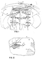
- Figure 1 is a schematic representation of a patient's head positioned in stereotactic head frame. An electromagnet device with an energy beam generator are shown in place.
- Figure 2 shows a video display displaying 3-D coordinates of ball position within the brain. Cross hairs depict ball position relative to the tumor, eloquent brain, and vasculative tubular structures.
- Figure 3 shows a screen schematic when a surgeon has advanced the ball and is now closing in on the tumor.
- Figure 4 shows a screen schematic with the ball advanced into the substance of the tumor.
- Figure 5 shows a screen when an energy beam is fired into the ball.
- Figure 6 shows a computer screen image of defect caused by the heated ball.
- Figure 7 is a schematic representation of a tumor within a brain and a metallic object within a tumor for focusing destructive energy therein and showing an affected zone around the metallic object.
- Figure 8 is a schematic drawing of a brain showing a tumor in shaded form within a brain and an energy focusing object within the tumor together with a path by which the object has been inserted in the tumor.
- Figure 9 is a schematic representation of a physician at a control used for moving an object within a brain and guiding the object into a tumor and heating the object.
- Figure 10 shows a flowchart of steps needed to operate the video tumor fighter so as to destroy a tumor.
- An upper skull bridging member 19 has similar adjusting and contacting screws 15 and 17.
- a lower member 21 is forked 23 to receive the base of the skull.
- An adjustment screw 15 holds the forked skull base member in fixed position.
- a mouthpiece is cantilevered on member 25, which is held in place by adjustment screw 15.
- a chin-supporting member 27 is also held in place by an adjusting screw 15.
- the entire stereotactic frame device which is generally indicated by tile numeral 29, is made of suitable material.
- an electromagnet device 31 Surrounding the stereotactic headframe is an electromagnet device 31 shown cutaway, which is suspended on cables 33 from the ceiling or from an overhead frame.
- An energy beam generator 41 is positioned on an adjustable tracking device 43 which includes a hinge 45 and a slide 47 mounted on a track 49.
- a radial inward portion of track 49 is supported on a device 51, which is in turn supported from the ceiling or from an overhead frame.
- the device may be used in any orientation, although a vertical orientation is shown in the drawing.
- the patient's skull is placed or maintained in the identical position in the headframe during the surgical procedure.
- a small scalp flap is opened, and a small hole is drilled in the skull.
- a small magnetic object such as a ball or a cylinder with rounded ends, is placed in the opening.
- Figure 2 shows a video display screen 61 which displays three-dimensional coordinates of a fluoroscopic image 63 of an object positioned within a computer-stored and reproduced image of the brain generally indicated by the numeral 65. Eloquent volumes of the brain 67, which are to be avoided, are displayed on the screen. Images from a double fluoroscopic unit are combined into a three-dimensional image within the computer. Using conventional techniques, the screen image may be shifted to effectively observe the brain, tumor and surgical object from any angle.
- Vascular tubular structures 71 such as artery 73 and capillaries 75, are displayed.
- a three-dimensional image of a tumor 77 is also displayed.
- Cross-hairs 79 depict the object position relative to the tumor, to the eloquent brain volumes, and to the vascular tubular structures.
- Figure 4 depicts a larger scale on the screen, with the object image 63 advanced into the substance of tumor 77.
- Figure 5 shows an image of the screen as the energy beam is fired into the object, heating the object.
- the image shown on the screen shows an expanded image 81 of the heated object with fine cross-hairs 79 and radiating lines 83, together, which indicates heat penetration into the tumor 77.
- the enlarged heated volume may be displayed such as in a different color and may be stored in the computer memory to indicate a heat treated destroyed tumor portion.
- the object may be advanced, stopped, heated, and moved sequentially until the tumor is substantially or totally destroyed. Alternatively, the object may be continuously heated as it is moved within the tumor.
- Figure 6 shows the computer image of a defect or lesion 87 created in the tumor 77 as caused by the heated object 63.
- Figure 7 shows a schematic representation of a tumor 77 in which an energy receiving object 63 has been positioned. Irradiating the object 63 with energy has caused an expanded affected zone 84 around the object.
- the prior or intended path of the object 63 is indicated by the broken lines which are identified by 63'.
- the broken lines identified by 84' identify the affected zones from prior positioning of the object 63 or the zones which will be intended to be affected by subsequent positions of object 63.
- Figure 8 is a schematic representation of a brain 65 in which an object 63 has been steered into a tumor 77.
- the dotted line indicated by the numeral 85 indicates the path through which the object has been steered into the tumor 77.
- the dotted line indicated by the numeral 85 indicates the path through which the object has been steered into the tumor.
- Figure 9 shows the image of an object 63 within a tumor 77 in a brain 65 shown on display 86.
- a computer console 87 as controlled by terminal 89 and a guidance control 91 operated by a doctor 93 steers object 63 through the brain and heats the object with radio frequency energy beams.
- the computer 87 is used to record physiological data of the brain from MRI and/or CT scans and angiograms and is used to store and reproduce that data to form the image 65 of the brain on the display and is used to correlate the real time imaging of the object 63 with the previously recorded data and to concurrently display the images.
- Figure 10 is a flowchart of steps.
- the first step is to fix a patient's skull 101 in the stereotactic device.
- a CT scan 103 and MRI and/or an angiogram 105 are performed.
- Data is entered 107 in a computer, and an image is produced 109 on a screen 111.
- Known eloquent brain volumes 113 are entered in the computer and identified as distinct images on the screen.
- the patient's scalp is cut and the skull is drilled 115.
- An object is inserted 117 through the opening in the skull and the object is steered 119 through the brain by moving the magnet and/or by adjusting its strength.
- the steering of the object through the brain is recorded 123.
- the object is moved 125 into the tumor and is heated 127 until the surrounding tumor tissue dies. Steps 125 and 127 are repeated 129 and finally the object is left in the brain and is steered 131 out of the brain, such as along its entry path by data read 133 from the recorded data.
- a cooled or super conducting coil constitutes the electromagnet, which provides the magnetic field to manipulate the object.
- the magnet is moved around the stationary head frame to position the object within the brain.
- the object is any suitable object which has sufficient magnetic qualities to be manipulated within a brain by the field of the electromagnet. Larger objects are usually easier to manipulate. Permanent magnets of increased strength are usually easier to manipulate. Smaller objects are easier to move through a brain. Shape differences may promote energy absorption and/or movement. Objects may be coated with materials which promote radio frequency (rf) heating or conducting heat to surrounding tissue. Tumor cells are killed at slightly lower temperature than healthy brain cells. Temperatures appropriate to different vascularities, different tumor types and locations, different rates of object motion and other factors may vary.
- rf radio frequency
- a patient's head is scanned and an image of a brain is produced and stored in a computer.
- An angiogram may be used to produce a display of and store data concerning vascular structure of the brain.
- a patient's skull is drilled and a small metallic object about 1/8th of an inch in diameter is placed within the hole.
- the stored image of the patient's brain and the real time image of the metallic object are correlated by the computer and a physician uses computer controls to change position and strength of a magnet adjacent the patient's head to steer the metallic object through the brain.
- the physician energizes a radio frequency generator to direct a beam to the object and heat the object.
- the beam which for example may be a radio frequency beam extends through the patient's head and brain and excites the metallic object, causing it to heat.
- the radio frequency energy passes through the watery cells of the brain and the bone cells of the skull without causing damage to those healthy cells.
- the only change noted is the increased temperature of the object which is in its desired location.
- the object may be heated to a temperature which is sufficient to destroy tumor cells immediately adjacent the object and for a zone surrounding the object.
- a temperature which is sufficient to destroy tumor cells immediately adjacent the object and for a zone surrounding the object.
- the object When the object is positioned deep within a tumor, it may be heated to a greater degree or for a longer time.
- the object When the object is positioned near the border of the tumor and healthy cells, it may be heated for a shorter time or to a lesser degree.
- Many brain tumors are of a soft nature and can be penetrated by the object.
- the object may be moved along the tumor and heated to destroy or weaken peripheral tumor cells.
- healthy cells surrounding the tumor may be destroyed or weakened to interrupt outward progress of the tumor.
- a metallic object deep within a tumor may be heated to a temperature of up to about 150 degrees F. or more.
- An object near the interface of a tumor and healthy tissue may be heated to a temperature of about 110 degrees F., for example.
Landscapes
- Health & Medical Sciences (AREA)
- Engineering & Computer Science (AREA)
- Life Sciences & Earth Sciences (AREA)
- Surgery (AREA)
- General Health & Medical Sciences (AREA)
- Biomedical Technology (AREA)
- Veterinary Medicine (AREA)
- Public Health (AREA)
- Animal Behavior & Ethology (AREA)
- Nuclear Medicine, Radiotherapy & Molecular Imaging (AREA)
- Heart & Thoracic Surgery (AREA)
- Robotics (AREA)
- Medical Informatics (AREA)
- Molecular Biology (AREA)
- Radiology & Medical Imaging (AREA)
- Thermal Sciences (AREA)
- Vascular Medicine (AREA)
- Physics & Mathematics (AREA)
- Magnetic Resonance Imaging Apparatus (AREA)
- Medicines Containing Material From Animals Or Micro-Organisms (AREA)
- Thermotherapy And Cooling Therapy Devices (AREA)
Abstract
Description
- Conventional neurosurgery is limited in its ability to treat deep seated tumours because of the necessity of cutting through normal brain and vasculature to obtain access to the tumour. Radiation therapy carries with it the problems of high dose ionizing radiation which is both destructive to normal tissue and like chemotherapy oftentimes ineffective in stopping tumour growth.
- A fast growing malignancy deep inside the brain is difficult to treat because existing surgical procedures require cutting through or otherwise damaging normal brain structures. In general, both the patient's post-operative condition and his prognosis for recovery are often poor. Partly because of this, a research area has sprung up in which generalized hyperthermia, introduced by radio-frequency irradiation of the tumour's region, is used in an attempt to kill the tumour cells. If there were some way of sufficiently localizing hyperthermia to the tumour itself, hyperthermia could be a much more effective adjuvant or primary treatment for brain tumours.
- Production of focal brain lesions by inductive heating in se has yet been disclosed in US-A-3653385. Therein a metallic pellet or seed is implanted into the brain in a position where a brain lesion is to be produced. The seed is provided for being inductively heated by radio frequency energy, whereby a predetermined temperature is reached and not exceeded. Herewith a desired size and degree of lesion in the brain is controlled as a function of time during which the radio frequency field is in operation.
- There is known from US-A-4608977 a holding and immobilizing frame, a scanner, and a computer for inputting the data obtained from the scanner. However, said document relates to computed tomography.
- Further, magnetic propulsion of a therapeutic asymmetric element through the body ducts of humans is disclosed in US-A-3358676. Said asymmetric element has no center of symmetry and comprises a magnetic element, whereby magnetic field means impart a vibrational or rotational motion to said element, which is effected through ducts present or placed in the body. Said asymmetric element is rather complex as to the structure and has a heterogeneous composition.
- In the present invention, a tumour fighting apparatus is provided comprising magnetic object means for inserting in a body part, electromagnet means positioned outside of the body part for producing a magnetic field which captures the magnetic object means, the magnetic object means being moved within the body part to a desired location by said magnetic field, control means for controlling said electromagnet means; beam producing means for directing a beam into the body part and to the magnetic object means whereby the beam producing means is mounted adjacent the body part, observing means for observing the magnetic object means within the body part, remarkable in that said apparatus is a video apparatus further comprising firing means, said beam producing means being connected to said firing means, said firing means being controlled by the control means for controlling the firing of the beam into the body part at the magnetic object means, whereby the beam is an electromagnetic energy beam that is absorbed by the magnetic object, a frame for holding and immobilizing said body part, means for opening the envelope of the patient's tissue for inserting said small magnetic object within said opening in the envelope, a scanner for conducting a scan of said body part and obtaining data from the scan, a computer for inputting the data obtained from the scanner into said observing means for displaying three-dimensional images of the patent's tissue.
- According to a more specific embodiment of the invention, said observing means consists in a display unit for dispaying three-dimensional images of vascular tubular structures, eloquent tissue regions and tumours.
- According to a still more specific embodiment of the invention, said body part is formed by the patient's head, and said tissue structure is formed by the brain structure, said tissue by the brain respectively, and said envelope by the scalp and/or skull, whereby said opening means is provided for opening the scalp of the patient and drilling an opening in the skull for inserting said small magnetic object within said opening in the skull.
- A destructive stereotactic heat lesion is placed precisely in any location in the brain without significant damage to surrounding areas. Incorporating principles of physics, computer science and neuroanatomy, this apparatus enables neurosurgeons to safely destroy pathologic lesions, while sparing normal brain tissue.
- The advantages of this apparatus are several. Previously inaccessible brain tumours are safely destroyed without cutting through and damaging eloquent areas of brain.
- All brain tumours, regardless of their location, are destroyed with much greater precision and less damage to surrounding brain.
- Subsequent procedures to treat residual tumour, that may have been missed the first time can be performed with much less difficulty than the first procedure.
- Subsequent procedures to treat residual tumour that may have been missed the first time can be performed with much less difficulty than with other treatment apparatus.
- No material tether for guidance or pushing rod for emplacement is necessary.
- The procedure may be performed under local anesthesia with the heat lesion destroying the tumour. Operative morbidity and mortality are decreased.
- Ionizing radiation is not used as a destructive force. The side effects of chimiotherapy can be avoided. The potential damage of generalized hyperthermia is avoided. This device has a broad range of surgical applications in addition to destroying tumours.
- The present invention is an entirely new and revolutionary approach to destroying brain tumours. There are two fundamental principles of physics incoporated into this system. The first involves suspension and/or manipulation of said small magnetic object in space using an electromagnet. This technology is currently available and has the capacity to move and position an object in space with less than 1 mm error. It has been found that the brain's soft composition enables a small ball or other object to be moved through it in this fashion.
- This invention further entails directing an energy beam, for example a radio frequency electromagnetic wave, which is preferentially absorbed by the suspended object. Because of the difference in atomic composition between the object and brain tissue, the object absorbs the energy as heat much more efficiently than brain tissue. Only a discrete area of tissue surrounding the heated object is destroyed. Our studies in directing electromagnetic energy at particles embedded in mammalian brains have proved this principle.
- Either of two methods are employed individually in a variety of clinical applications. The preferred application involves computer integration of the systems, taking advantage of advanced imaging techniques to produce a precision video tumour fighter. This system operates as follows:
- The patient's head is secured within a stereotactic frame. High resolution CT scan and angiogram or MRI (Magnetic Resonance Imaging) studies are then performed. Data is incorporated and analyzed by computer. Three dimentional coordinates occupied by vascular structures, tumour, or eloquent areas of brain are recorded. The eloquent areas of brain are defined previously using a conventional stereotactic atlas and programming these loci into the software. This information is then resynthesized and projected as a video image on a screen facing the surgeon. This image recreates the spatial relationship between the position of the object and the previously mentioned areas of importance in a form that can be understood by the surgeon and enables him to avoid zones of danger and minimize damage as he makes his approach to the tumor. This technique of computer imaging of three dimensional structures for the purpose of avoiding zones of danger used in advanced attack aircraft is adaptable to the tumor fighter.
- After imaging is complete, an incision is made through the scalp, a burr hole is drilled, dura reflected and the object is placed on the exposed brain. The surgeon takes his position at the controls facing the video screen. The magnet is positioned and activated. Using an appropriate real time imaging method in conjunction with the previously stored imaging data, the surgeon avoids danger zones as he pilots the object into the tumor. Once the object is within the tumor, the energy beam is fired at the object. The object is heated, and it destroys a small area of surrounding tissue. This loss is projected on the screen as a defect in the tumor image, the size of which is dependent on the energy setting of the beam and the length of fire time. The object is further advanced into the tumor, the energy beam is fired again, perhaps this time from a slightly different angle, still energizing the object, but passing through a different line of normal brain tissue to avoid excessive exposure of one tract of tissue. This procedure is repeated until the entire tumor is eradicated. Finally, the object is left suspended within the brain for further use or the computer directs the object back to the burr hole, or the surgeon carefully pilots the object back to the burr hole. The object is removed and the skin closed.
- These and other and further objects and features of the invention are apparent in the disclosure, which includes the above and ongoing description, drawings and claims.
- Figure 1 is a schematic representation of a patient's head positioned in stereotactic head frame. An electromagnet device with an energy beam generator are shown in place.
- Figure 2 shows a video display displaying 3-D coordinates of ball position within the brain. Cross hairs depict ball position relative to the tumor, eloquent brain, and vasculative tubular structures.
- Figure 3 shows a screen schematic when a surgeon has advanced the ball and is now closing in on the tumor.
- Figure 4 shows a screen schematic with the ball advanced into the substance of the tumor.
- Figure 5 shows a screen when an energy beam is fired into the ball.
- Figure 6 shows a computer screen image of defect caused by the heated ball.
- Figure 7 is a schematic representation of a tumor within a brain and a metallic object within a tumor for focusing destructive energy therein and showing an affected zone around the metallic object.
- Figure 8 is a schematic drawing of a brain showing a tumor in shaded form within a brain and an energy focusing object within the tumor together with a path by which the object has been inserted in the tumor.
- Figure 9 is a schematic representation of a physician at a control used for moving an object within a brain and guiding the object into a tumor and heating the object.
- Figure 10 shows a flowchart of steps needed to operate the video tumor fighter so as to destroy a tumor.
- Referring to Figure 1, a video tumor fighter of the present invention is generally indicated by the numeral 1. A
frame 3 surrounds a patient'shead 5 and holds the head in fixed position relative to the frame. Theframe 3 haslongitudinal members 7 which may be anchored infixed structure 9. A circular member 11 is joined to thelongitudinal members 7. A moveable centralcircular member 13 has adjustment screws 15 for holding the central member at a fixed position and has skull orscalp contacting screws 17 for contacting the skull or scalp of the patient. - An upper
skull bridging member 19 has similar adjusting and contactingscrews lower member 21 is forked 23 to receive the base of the skull. Anadjustment screw 15 holds the forked skull base member in fixed position. A mouthpiece is cantilevered onmember 25, which is held in place byadjustment screw 15. A chin-supportingmember 27 is also held in place by an adjustingscrew 15. The entire stereotactic frame device, which is generally indicated bytile numeral 29, is made of suitable material. During the CAT-scan and MRI procedure, the position of the skull with respect to the head-frame is sensed and is recorded in the computer-stored data. - Surrounding the stereotactic headframe is an
electromagnet device 31 shown cutaway, which is suspended oncables 33 from the ceiling or from an overhead frame. Anenergy beam generator 41 is positioned on anadjustable tracking device 43 which includes ahinge 45 and aslide 47 mounted on atrack 49. A radial inward portion oftrack 49 is supported on adevice 51, which is in turn supported from the ceiling or from an overhead frame. The device may be used in any orientation, although a vertical orientation is shown in the drawing. The patient's skull is placed or maintained in the identical position in the headframe during the surgical procedure. A small scalp flap is opened, and a small hole is drilled in the skull. A small magnetic object, such as a ball or a cylinder with rounded ends, is placed in the opening. - Figure 2 shows a
video display screen 61 which displays three-dimensional coordinates of afluoroscopic image 63 of an object positioned within a computer-stored and reproduced image of the brain generally indicated by the numeral 65. Eloquent volumes of thebrain 67, which are to be avoided, are displayed on the screen. Images from a double fluoroscopic unit are combined into a three-dimensional image within the computer. Using conventional techniques, the screen image may be shifted to effectively observe the brain, tumor and surgical object from any angle. - Vascular
tubular structures 71, such asartery 73 andcapillaries 75, are displayed. A three-dimensional image of atumor 77 is also displayed. Cross-hairs 79 depict the object position relative to the tumor, to the eloquent brain volumes, and to the vascular tubular structures. - As shown in Figure 3, as the
image 63 of the object is advanced near thetumor 77, the cross-hairs 79 indicate the precise position of the object. - Figure 4 depicts a larger scale on the screen, with the
object image 63 advanced into the substance oftumor 77. - Figure 5 shows an image of the screen as the energy beam is fired into the object, heating the object. The image shown on the screen shows an expanded
image 81 of the heated object with fine cross-hairs 79 and radiatinglines 83, together, which indicates heat penetration into thetumor 77. The enlarged heated volume may be displayed such as in a different color and may be stored in the computer memory to indicate a heat treated destroyed tumor portion. The object may be advanced, stopped, heated, and moved sequentially until the tumor is substantially or totally destroyed. Alternatively, the object may be continuously heated as it is moved within the tumor. - Figure 6 shows the computer image of a defect or
lesion 87 created in thetumor 77 as caused by theheated object 63. - Figure 7 shows a schematic representation of a
tumor 77 in which anenergy receiving object 63 has been positioned. Irradiating theobject 63 with energy has caused an expanded affectedzone 84 around the object. As shown in the drawings the prior or intended path of theobject 63 is indicated by the broken lines which are identified by 63'. The broken lines identified by 84' identify the affected zones from prior positioning of theobject 63 or the zones which will be intended to be affected by subsequent positions ofobject 63. - Figure 8 is a schematic representation of a
brain 65 in which anobject 63 has been steered into atumor 77. The dotted line indicated by the numeral 85 indicates the path through which the object has been steered into thetumor 77. The dotted line indicated by the numeral 85 indicates the path through which the object has been steered into the tumor. - Figure 9 shows the image of an
object 63 within atumor 77 in abrain 65 shown on display 86. Acomputer console 87 as controlled byterminal 89 and aguidance control 91 operated by adoctor 93 steers object 63 through the brain and heats the object with radio frequency energy beams. - The
computer 87 is used to record physiological data of the brain from MRI and/or CT scans and angiograms and is used to store and reproduce that data to form theimage 65 of the brain on the display and is used to correlate the real time imaging of theobject 63 with the previously recorded data and to concurrently display the images. - Figure 10 is a flowchart of steps. The first step is to fix a patient's
skull 101 in the stereotactic device. Then aCT scan 103 and MRI and/or anangiogram 105 are performed. Data is entered 107 in a computer, and an image is produced 109 on a screen 111. Knowneloquent brain volumes 113 are entered in the computer and identified as distinct images on the screen. The patient's scalp is cut and the skull is drilled 115. An object is inserted 117 through the opening in the skull and the object is steered 119 through the brain by moving the magnet and/or by adjusting its strength. The steering of the object through the brain is recorded 123. The object is moved 125 into the tumor and is heated 127 until the surrounding tumor tissue dies.Steps - Preferably, a cooled or super conducting coil constitutes the electromagnet, which provides the magnetic field to manipulate the object. The magnet is moved around the stationary head frame to position the object within the brain. The object is any suitable object which has sufficient magnetic qualities to be manipulated within a brain by the field of the electromagnet. Larger objects are usually easier to manipulate. Permanent magnets of increased strength are usually easier to manipulate. Smaller objects are easier to move through a brain. Shape differences may promote energy absorption and/or movement. Objects may be coated with materials which promote radio frequency (rf) heating or conducting heat to surrounding tissue. Tumor cells are killed at slightly lower temperature than healthy brain cells. Temperatures appropriate to different vascularities, different tumor types and locations, different rates of object motion and other factors may vary. As an example, a patient's head is scanned and an image of a brain is produced and stored in a computer. An angiogram may be used to produce a display of and store data concerning vascular structure of the brain. A patient's skull is drilled and a small metallic object about 1/8th of an inch in diameter is placed within the hole. The stored image of the patient's brain and the real time image of the metallic object are correlated by the computer and a physician uses computer controls to change position and strength of a magnet adjacent the patient's head to steer the metallic object through the brain. When the object appears on the display to be within the area of the previously recorded tumor, the physician energizes a radio frequency generator to direct a beam to the object and heat the object. The beam which for example may be a radio frequency beam extends through the patient's head and brain and excites the metallic object, causing it to heat. The radio frequency energy passes through the watery cells of the brain and the bone cells of the skull without causing damage to those healthy cells. The only change noted is the increased temperature of the object which is in its desired location.
- Advantageously, the object may be heated to a temperature which is sufficient to destroy tumor cells immediately adjacent the object and for a zone surrounding the object. When the object is positioned deep within a tumor, it may be heated to a greater degree or for a longer time. When the object is positioned near the border of the tumor and healthy cells, it may be heated for a shorter time or to a lesser degree.
- Many brain tumors are of a soft nature and can be penetrated by the object. In the event that a tumor cannot be penetrated by the object, the object may be moved along the tumor and heated to destroy or weaken peripheral tumor cells. Advantageously, if the tumor is not penetrable by the object, healthy cells surrounding the tumor may be destroyed or weakened to interrupt outward progress of the tumor.
- As an example, a metallic object deep within a tumor may be heated to a temperature of up to about 150 degrees F. or more. An object near the interface of a tumor and healthy tissue may be heated to a temperature of about 110 degrees F., for example.
- While the invention has been described with reference to specific embodiments, modifications and variations may be made without departing from the scope of the invention which is defined in the following claims.
Claims (14)
- A tumour fighting apparatus comprising:magnetic object means (63) for inserting in a body part (5),electromagnet means (31) positioned outside of the body part (5) for producing a magnetic field which captures the magnetic object means (63),the magnetic object means (63) being movable within the body part (5) to a desired location by said magnetic field,control means for controlling said electromagnet means;beam producing means (41) for directing a beam into the body part (5) and to the magnetic object means (63) whereby the beam producing means (41) is mounted adjacent the body part (5),observing means (61) for observing the magnetic object means (63) within the body part (5),characterised in that said apparatus is a video apparatus further comprising:firing means, said beam producing means (41) being connected to said firing means,said firing means being controlled by the control means for controlling the firing of the beam into the body part (5) at the magnetic object means (63), whereby the beam is an electromagnetic energy beam that is absorbed by the magnetic object,a frame (3, 29) for holding and immobilizing said body part (5),means for opening the envelope of the patient's tissue (65) for inserting said small magnetic object (63) within said opening in the envelope,a scanner for conducting a scan of said body part (5) and obtaining data from the scan,a computer (88) for inputting the data obtained from the scanner into said observing means for displaying three-dimensional images of the patient's tissue (65).
- An apparatus according to claim 1, characterised in that said observing means consists in a display unit (61) for displaying three-dimensional images of vascular tubular structures (71;73,75), eloquent tissue regions (67) and tumours (77).
- An apparatus according to claim 1 or 2, characterised in that said body part (5) is formed by the patient's head, and in that said tissue structure (71;73,75) is formed by the brain structure, said tissue (65) by the brain respectively, and said envelope by the scalp and/or skull, whereby said opening means is provided for opening the scalp of the patient and drilling an opening in the skull for inserting said small magnetic object (63) within said opening in the skull.
- An apparatus acccording to one of the preceding claims, characterised in that it further comprises positioning means (43) connected to said electromagnet means (31) for moving the electromagnet means adjacent the body part (5), whereby said electromagnet means (31) are arranged for moving said magnetic object means (63), said control means being connected to said positioning means for controlling the movement of said electromagnet means (31).
- An apparatus according to one of the claims 2 to 4, characterised in that said electromagnetic means comprises an electromagnet (31) for placing around said envelope having a control means (91) for controlling movement of the object (63) within the envelope and tissue (65) by changing a magnetic field size and direction of the electromagnet (31) and steering the movement of the object within the envelope and tissue (65) to avoid eloquent regions (67) of the tissue (65) and vascular tubular structures (71; 73, 75) and guiding the object (63) into contact with and into a position within the tumour (77) and guiding the object (63) outward from lesions (87) and directing the object (63) to the opening in the envelope and removing the object (63) from the envelope through the opening;means (45,47,49) for moving the energy beam generator (41) into a position to direct energy to the object (63) within the tumour (77);means for energizing the energy beam generator (41) and directing energy from the beam generator (41) into the object (63) for heating the object (63) and creating said lesion (87) within the tumour (77) in a region (84) surrounding the object (63) by heat from the object (63) and repeating the process at different locations.
- An apparatus according to any of the claims 2 to 5, characterised by further comprising :a power source for supplying power to the electromagnet (31), wherein the electromagnet (31) is movable outside the envelope and controls and steers the movement of the magnetic object (63) within the tissue (65) avoiding eloquent regions (67) and vascular tubular structures (71;73,75) of the tissue (65) and guides the object (63) into contact with and into a position within the tumour (77).
- The apparatus according to any of the claims 2 to 6, characterised in that the energy beam generator (41) directs the subsequent energy beam after being relocated to direct the energy beam through regions (84') of the envelope and tissue (65) through which energy beam has not previously been directed.
- The apparatus according to any of the preceding claims, characterised in that the electromagnet (31) steers the object (63) out of the tumour (77) and through the tissue (65) to the envelope through the same path (85) in which the object (63) was steered through the tissue (65) toward the tumour (77).
- The apparatus according to any of the preceding claims, characterised by further comprising a predetermined image of the tissue (65) for superimposing real time fluoroscopic images of the tissue (65) received from the scanner to facilitate guidance of the object (63).
- The apparatus according to any of the preceding claims, characterised in that the electromagnet (31) causes the object (63) to be moved continuously and the energy beam generator (41) heats the object (63) simultaneously as needed to obtain the desired effects.
- The apparatus according to any of the preceding claims, characterised by further comprising treatment means cooperating with the magnetic object (63) being located at the desired location in the body.
- The apparatus according to claim 11, the treatment means comprises hyperthermia treatment means for delivering hyperthermia treatment.
- The apparatus according to claim 11 or 12, characterised in that the treatment means comprises chemotherapy treatment means for delivering chemotherapy treatment.
- The apparatus according to one of the claims 11 to 13, characterised in that the treatment means comprises radiotherapy treatment means for delivering radiotherapy treatment.
Applications Claiming Priority (3)
| Application Number | Priority Date | Filing Date | Title |
|---|---|---|---|
| US167217 | 1988-03-11 | ||
| US07/167,217 US4869247A (en) | 1988-03-11 | 1988-03-11 | Video tumor fighting system |
| PCT/US1989/000920 WO1989008430A1 (en) | 1988-03-11 | 1989-03-09 | Video tumor fighting system |
Publications (3)
| Publication Number | Publication Date |
|---|---|
| EP0434684A1 EP0434684A1 (en) | 1991-07-03 |
| EP0434684A4 EP0434684A4 (en) | 1991-08-07 |
| EP0434684B1 true EP0434684B1 (en) | 1997-05-28 |
Family
ID=22606436
Family Applications (1)
| Application Number | Title | Priority Date | Filing Date |
|---|---|---|---|
| EP89904345A Expired - Lifetime EP0434684B1 (en) | 1988-03-11 | 1989-03-09 | Video tumor fighting system |
Country Status (6)
| Country | Link |
|---|---|
| US (1) | US4869247A (en) |
| EP (1) | EP0434684B1 (en) |
| AT (1) | ATE153520T1 (en) |
| CA (1) | CA1332754C (en) |
| DE (1) | DE68928081T2 (en) |
| WO (1) | WO1989008430A1 (en) |
Families Citing this family (177)
| Publication number | Priority date | Publication date | Assignee | Title |
|---|---|---|---|---|
| US4991579A (en) * | 1987-11-10 | 1991-02-12 | Allen George S | Method and apparatus for providing related images over time of a portion of the anatomy using fiducial implants |
| GB8728150D0 (en) | 1987-12-02 | 1988-01-06 | Inst Of Neurology Queen Square | Head fixation apparatus |
| US6331180B1 (en) | 1988-05-03 | 2001-12-18 | Sherwood Services Ag | Target-centered stereotaxtic surgical arc system with reorientatable arc axis |
| US5417212A (en) * | 1988-11-21 | 1995-05-23 | Szeles; Josef C. | Apparatus for determining the location of receptor regions |
| FR2652928B1 (en) | 1989-10-05 | 1994-07-29 | Diadix Sa | INTERACTIVE LOCAL INTERVENTION SYSTEM WITHIN A AREA OF A NON-HOMOGENEOUS STRUCTURE. |
| US5078142A (en) * | 1989-11-21 | 1992-01-07 | Fischer Imaging Corporation | Precision mammographic needle biopsy system |
| US5415169A (en) * | 1989-11-21 | 1995-05-16 | Fischer Imaging Corporation | Motorized mammographic biopsy apparatus |
| US5125888A (en) | 1990-01-10 | 1992-06-30 | University Of Virginia Alumni Patents Foundation | Magnetic stereotactic system for treatment delivery |
| US5224492A (en) * | 1990-06-13 | 1993-07-06 | Omron Corporation | Thermotherapy apparatus |
| US5190539A (en) * | 1990-07-10 | 1993-03-02 | Texas A & M University System | Micro-heat-pipe catheter |
| US5417686A (en) * | 1990-07-10 | 1995-05-23 | The Texas A&M University System | Temperature control mechanisms for a micro heat pipe catheter |
| US6196226B1 (en) | 1990-08-10 | 2001-03-06 | University Of Washington | Methods and apparatus for optically imaging neuronal tissue and activity |
| US5215095A (en) * | 1990-08-10 | 1993-06-01 | University Technologies International | Optical imaging system for neurosurgery |
| US6671540B1 (en) | 1990-08-10 | 2003-12-30 | Daryl W. Hochman | Methods and systems for detecting abnormal tissue using spectroscopic techniques |
| US5845639A (en) * | 1990-08-10 | 1998-12-08 | Board Of Regents Of The University Of Washington | Optical imaging methods |
| US5452720A (en) * | 1990-09-05 | 1995-09-26 | Photoelectron Corporation | Method for treating brain tumors |
| US6405072B1 (en) * | 1991-01-28 | 2002-06-11 | Sherwood Services Ag | Apparatus and method for determining a location of an anatomical target with reference to a medical apparatus |
| US6006126A (en) * | 1991-01-28 | 1999-12-21 | Cosman; Eric R. | System and method for stereotactic registration of image scan data |
| US6167295A (en) * | 1991-01-28 | 2000-12-26 | Radionics, Inc. | Optical and computer graphic stereotactic localizer |
| US5662111A (en) | 1991-01-28 | 1997-09-02 | Cosman; Eric R. | Process of stereotactic optical navigation |
| US5540737A (en) * | 1991-06-26 | 1996-07-30 | Massachusetts Institute Of Technology | Minimally invasive monopole phased array hyperthermia applicators and method for treating breast carcinomas |
| US5441532A (en) * | 1991-06-26 | 1995-08-15 | Massachusetts Institute Of Technology | Adaptive focusing and nulling hyperthermia annular and monopole phased array applicators |
| US5341292A (en) * | 1992-06-04 | 1994-08-23 | New England Medical Center Hospitals, Inc. | Monte Carlo based treatment planning for neutron capture therapy |
| US5913820A (en) | 1992-08-14 | 1999-06-22 | British Telecommunications Public Limited Company | Position location system |
| US5386447A (en) * | 1992-09-23 | 1995-01-31 | Fischer Imaging Corporation | Mammographic screening and biopsy apparatus |
| US5433717A (en) * | 1993-03-23 | 1995-07-18 | The Regents Of The University Of California | Magnetic resonance imaging assisted cryosurgery |
| US5380336A (en) * | 1993-04-16 | 1995-01-10 | John Misko | Method and apparatus for stereotactic radiosurgery and fractionated radiation therapy |
| US5373844A (en) * | 1993-06-14 | 1994-12-20 | The Regents Of The University Of California | Inverse treatment planning method and apparatus for stereotactic radiosurgery |
| WO1995011627A1 (en) * | 1993-10-29 | 1995-05-04 | Neovision Corporation | Methods and apparatus for performing sonomammography and enhanced x-ray imaging |
| US5983123A (en) * | 1993-10-29 | 1999-11-09 | United States Surgical Corporation | Methods and apparatus for performing ultrasound and enhanced X-ray imaging |
| WO1996003087A1 (en) * | 1994-07-22 | 1996-02-08 | University Of Washington | Methods for stereotactic implantation |
| US5654864A (en) * | 1994-07-25 | 1997-08-05 | University Of Virginia Patent Foundation | Control method for magnetic stereotaxis system |
| US5829444A (en) | 1994-09-15 | 1998-11-03 | Visualization Technology, Inc. | Position tracking and imaging system for use in medical applications |
| ATE252349T1 (en) | 1994-09-15 | 2003-11-15 | Visualization Technology Inc | SYSTEM FOR POSITION DETECTION USING A REFERENCE UNIT ATTACHED TO A PATIENT'S HEAD FOR USE IN THE MEDICAL FIELD |
| US5833627A (en) * | 1995-04-13 | 1998-11-10 | United States Surgical Corporation | Image-guided biopsy apparatus and methods of use |
| SG64340A1 (en) * | 1996-02-27 | 1999-04-27 | Inst Of Systems Science Nation | Curved surgical instruments and methods of mapping a curved path for stereotactic surgery |
| US5820552A (en) * | 1996-07-12 | 1998-10-13 | United States Surgical Corporation | Sonography and biopsy apparatus |
| US5851180A (en) * | 1996-07-12 | 1998-12-22 | United States Surgical Corporation | Traction-inducing compression assembly for enhanced tissue imaging |
| US6296613B1 (en) | 1997-08-22 | 2001-10-02 | Synthes (U.S.A.) | 3D ultrasound recording device |
| US5776062A (en) * | 1996-10-15 | 1998-07-07 | Fischer Imaging Corporation | Enhanced breast imaging/biopsy system employing targeted ultrasound |
| US5845646A (en) * | 1996-11-05 | 1998-12-08 | Lemelson; Jerome | System and method for treating select tissue in a living being |
| US7048716B1 (en) | 1997-05-15 | 2006-05-23 | Stanford University | MR-compatible devices |
| US6267769B1 (en) | 1997-05-15 | 2001-07-31 | Regents Of The Universitiy Of Minnesota | Trajectory guide method and apparatus for use in magnetic resonance and computerized tomographic scanners |
| US6752812B1 (en) | 1997-05-15 | 2004-06-22 | Regent Of The University Of Minnesota | Remote actuation of trajectory guide |
| US6272370B1 (en) | 1998-08-07 | 2001-08-07 | The Regents Of University Of Minnesota | MR-visible medical device for neurological interventions using nonlinear magnetic stereotaxis and a method imaging |
| US5836878A (en) * | 1997-08-11 | 1998-11-17 | Wisconsin Alumni Research Foundation | Head restraint method and apparatus for use in MRI |
| US6128174A (en) * | 1997-08-29 | 2000-10-03 | Stereotaxis, Inc. | Method and apparatus for rapidly changing a magnetic field produced by electromagnets |
| US6015414A (en) | 1997-08-29 | 2000-01-18 | Stereotaxis, Inc. | Method and apparatus for magnetically controlling motion direction of a mechanically pushed catheter |
| US6226548B1 (en) | 1997-09-24 | 2001-05-01 | Surgical Navigation Technologies, Inc. | Percutaneous registration apparatus and method for use in computer-assisted surgical navigation |
| US6014580A (en) * | 1997-11-12 | 2000-01-11 | Stereotaxis, Inc. | Device and method for specifying magnetic field for surgical applications |
| US6212419B1 (en) | 1997-11-12 | 2001-04-03 | Walter M. Blume | Method and apparatus using shaped field of repositionable magnet to guide implant |
| US6157853A (en) * | 1997-11-12 | 2000-12-05 | Stereotaxis, Inc. | Method and apparatus using shaped field of repositionable magnet to guide implant |
| US6021343A (en) | 1997-11-20 | 2000-02-01 | Surgical Navigation Technologies | Image guided awl/tap/screwdriver |
| US6348058B1 (en) | 1997-12-12 | 2002-02-19 | Surgical Navigation Technologies, Inc. | Image guided spinal surgery guide, system, and method for use thereof |
| US6463317B1 (en) | 1998-05-19 | 2002-10-08 | Regents Of The University Of Minnesota | Device and method for the endovascular treatment of aneurysms |
| US6132360A (en) * | 1998-05-22 | 2000-10-17 | Halpern; Alan A. | Magnetic stretching of magnetized neurons for spinal cord or peripheral nerve repair and regeneration |
| US6027457A (en) * | 1998-06-18 | 2000-02-22 | United States Surgical Corporation | Apparatus and method for securing tissue during ultrasound examination and biopsy |
| CA2335867C (en) | 1998-06-22 | 2008-12-30 | Synthes (U.S.A.) | Fiducial matching by means of fiducial screws |
| EP1115327A4 (en) | 1998-08-07 | 2007-06-20 | Stereotaxis Inc | Method and apparatus for magnetically controlling catheters in body lumens and cavities |
| US6477400B1 (en) | 1998-08-20 | 2002-11-05 | Sofamor Danek Holdings, Inc. | Fluoroscopic image guided orthopaedic surgery system with intraoperative registration |
| US6298259B1 (en) | 1998-10-16 | 2001-10-02 | Univ Minnesota | Combined magnetic resonance imaging and magnetic stereotaxis surgical apparatus and processes |
| US6241671B1 (en) * | 1998-11-03 | 2001-06-05 | Stereotaxis, Inc. | Open field system for magnetic surgery |
| WO2000051484A2 (en) | 1998-11-25 | 2000-09-08 | Fischer Imaging Corporation | User interface system for mammographic imager |
| US6611141B1 (en) | 1998-12-23 | 2003-08-26 | Howmedica Leibinger Inc | Hybrid 3-D probe tracked by multiple sensors |
| US6330467B1 (en) * | 1999-02-04 | 2001-12-11 | Stereotaxis, Inc. | Efficient magnet system for magnetically-assisted surgery |
| DE69931074T2 (en) | 1999-03-17 | 2006-11-16 | Synthes Ag Chur | DEVICE FOR PRESENTING AND PLANNING CRANE COATING OPERATIONS |
| US6470207B1 (en) | 1999-03-23 | 2002-10-22 | Surgical Navigation Technologies, Inc. | Navigational guidance via computer-assisted fluoroscopic imaging |
| US6902528B1 (en) * | 1999-04-14 | 2005-06-07 | Stereotaxis, Inc. | Method and apparatus for magnetically controlling endoscopes in body lumens and cavities |
| US6491699B1 (en) | 1999-04-20 | 2002-12-10 | Surgical Navigation Technologies, Inc. | Instrument guidance method and system for image guided surgery |
| WO2000063719A1 (en) | 1999-04-20 | 2000-10-26 | Synthes Ag Chur | Device for the percutaneous obtainment of 3d-coordinates on the surface of a human or animal organ |
| DE59905962D1 (en) | 1999-05-03 | 2003-07-17 | Synthes Ag | POSITION DETECTING DEVICE WITH AID TO DETERMINE THE DIRECTION OF THE GRAVITY VECTOR |
| US6747665B1 (en) * | 1999-05-10 | 2004-06-08 | Ge Medical Systems Global Technology Company, Llc | Semi-transparent medical image overlays |
| US6298257B1 (en) * | 1999-09-22 | 2001-10-02 | Sterotaxis, Inc. | Cardiac methods and system |
| US6287304B1 (en) | 1999-10-15 | 2001-09-11 | Neothermia Corporation | Interstitial cauterization of tissue volumes with electrosurgically deployed electrodes |
| US6493573B1 (en) | 1999-10-28 | 2002-12-10 | Winchester Development Associates | Method and system for navigating a catheter probe in the presence of field-influencing objects |
| US11331150B2 (en) | 1999-10-28 | 2022-05-17 | Medtronic Navigation, Inc. | Method and apparatus for surgical navigation |
| US8239001B2 (en) | 2003-10-17 | 2012-08-07 | Medtronic Navigation, Inc. | Method and apparatus for surgical navigation |
| US8644907B2 (en) | 1999-10-28 | 2014-02-04 | Medtronic Navigaton, Inc. | Method and apparatus for surgical navigation |
| US6499488B1 (en) | 1999-10-28 | 2002-12-31 | Winchester Development Associates | Surgical sensor |
| US7366562B2 (en) | 2003-10-17 | 2008-04-29 | Medtronic Navigation, Inc. | Method and apparatus for surgical navigation |
| US6474341B1 (en) | 1999-10-28 | 2002-11-05 | Surgical Navigation Technologies, Inc. | Surgical communication and power system |
| US6381485B1 (en) | 1999-10-28 | 2002-04-30 | Surgical Navigation Technologies, Inc. | Registration of human anatomy integrated for electromagnetic localization |
| US20010034530A1 (en) | 2000-01-27 | 2001-10-25 | Malackowski Donald W. | Surgery system |
| US6725080B2 (en) | 2000-03-01 | 2004-04-20 | Surgical Navigation Technologies, Inc. | Multiple cannula image guided tool for image guided procedures |
| US6497134B1 (en) | 2000-03-15 | 2002-12-24 | Image Guided Technologies, Inc. | Calibration of an instrument |
| US7660621B2 (en) | 2000-04-07 | 2010-02-09 | Medtronic, Inc. | Medical device introducer |
| US6535756B1 (en) | 2000-04-07 | 2003-03-18 | Surgical Navigation Technologies, Inc. | Trajectory storage apparatus and method for surgical navigation system |
| US7366561B2 (en) | 2000-04-07 | 2008-04-29 | Medtronic, Inc. | Robotic trajectory guide |
| US7085400B1 (en) | 2000-06-14 | 2006-08-01 | Surgical Navigation Technologies, Inc. | System and method for image based sensor calibration |
| AU2001285071A1 (en) | 2000-08-17 | 2002-02-25 | John David | Trajectory guide with instrument immobilizer |
| US20020103430A1 (en) * | 2001-01-29 | 2002-08-01 | Hastings Roger N. | Catheter navigation within an MR imaging device |
| US6842324B2 (en) * | 2001-04-05 | 2005-01-11 | Fsu Research Foundation, Inc. | Apparatus and method for controlling movement of an object through a medium using a magnetic field |
| US6636757B1 (en) | 2001-06-04 | 2003-10-21 | Surgical Navigation Technologies, Inc. | Method and apparatus for electromagnetic navigation of a surgical probe near a metal object |
| WO2003032837A1 (en) | 2001-10-12 | 2003-04-24 | University Of Florida | Computer controlled guidance of a biopsy needle |
| US7048756B2 (en) * | 2002-01-18 | 2006-05-23 | Apasara Medical Corporation | System, method and apparatus for evaluating tissue temperature |
| US6993394B2 (en) | 2002-01-18 | 2006-01-31 | Calfacion Corporation | System method and apparatus for localized heating of tissue |
| US6850804B2 (en) | 2002-01-18 | 2005-02-01 | Calfacior Corporation | System method and apparatus for localized heating of tissue |
| US6947786B2 (en) | 2002-02-28 | 2005-09-20 | Surgical Navigation Technologies, Inc. | Method and apparatus for perspective inversion |
| US6990368B2 (en) | 2002-04-04 | 2006-01-24 | Surgical Navigation Technologies, Inc. | Method and apparatus for virtual digital subtraction angiography |
| US8721655B2 (en) * | 2002-04-10 | 2014-05-13 | Stereotaxis, Inc. | Efficient closed loop feedback navigation |
| US20050256398A1 (en) * | 2004-05-12 | 2005-11-17 | Hastings Roger N | Systems and methods for interventional medicine |
| US7998062B2 (en) | 2004-03-29 | 2011-08-16 | Superdimension, Ltd. | Endoscope structures and techniques for navigating to a target in branched structure |
| AR039475A1 (en) * | 2002-05-01 | 2005-02-23 | Wyeth Corp | 6-ALQUILIDEN-PENEMS TRICICLICOS AS BETA-LACTAMASA INHIBITORS |
| US7769427B2 (en) * | 2002-07-16 | 2010-08-03 | Magnetics, Inc. | Apparatus and method for catheter guidance control and imaging |
| FR2843874B1 (en) | 2002-08-28 | 2004-11-05 | Centre Nat Rech Scient | NON-INVASIVE METHOD FOR OBTAINING A PREDETERMINED FIELD OF ACOUSTIC WAVES IN A SUBSTANTIALLY HOMOGENEOUS ENVIRONMENT MASKED BY A BONE BARRIER, IMAGING METHOD, AND DEVICE FOR CARRYING OUT SAID METHODS |
| US7704260B2 (en) | 2002-09-17 | 2010-04-27 | Medtronic, Inc. | Low profile instrument immobilizer |
| US7599730B2 (en) | 2002-11-19 | 2009-10-06 | Medtronic Navigation, Inc. | Navigation system for cardiac therapies |
| US7697972B2 (en) | 2002-11-19 | 2010-04-13 | Medtronic Navigation, Inc. | Navigation system for cardiac therapies |
| US7636596B2 (en) | 2002-12-20 | 2009-12-22 | Medtronic, Inc. | Organ access device and method |
| US7542791B2 (en) | 2003-01-30 | 2009-06-02 | Medtronic Navigation, Inc. | Method and apparatus for preplanning a surgical procedure |
| US7660623B2 (en) | 2003-01-30 | 2010-02-09 | Medtronic Navigation, Inc. | Six degree of freedom alignment display for medical procedures |
| US7559935B2 (en) | 2003-02-20 | 2009-07-14 | Medtronic, Inc. | Target depth locators for trajectory guide for introducing an instrument |
| US7896889B2 (en) | 2003-02-20 | 2011-03-01 | Medtronic, Inc. | Trajectory guide with angled or patterned lumens or height adjustment |
| US7570791B2 (en) | 2003-04-25 | 2009-08-04 | Medtronic Navigation, Inc. | Method and apparatus for performing 2D to 3D registration |
| EP1685535B1 (en) * | 2003-08-21 | 2014-04-30 | Philips Intellectual Property & Standards GmbH | Device and method for combining two images |
| US7313430B2 (en) | 2003-08-28 | 2007-12-25 | Medtronic Navigation, Inc. | Method and apparatus for performing stereotactic surgery |
| EP1667749B1 (en) | 2003-09-15 | 2009-08-05 | Super Dimension Ltd. | System of accessories for use with bronchoscopes |
| EP2316328B1 (en) | 2003-09-15 | 2012-05-09 | Super Dimension Ltd. | Wrap-around holding device for use with bronchoscopes |
| US7835778B2 (en) * | 2003-10-16 | 2010-11-16 | Medtronic Navigation, Inc. | Method and apparatus for surgical navigation of a multiple piece construct for implantation |
| US7840253B2 (en) | 2003-10-17 | 2010-11-23 | Medtronic Navigation, Inc. | Method and apparatus for surgical navigation |
| US7280863B2 (en) * | 2003-10-20 | 2007-10-09 | Magnetecs, Inc. | System and method for radar-assisted catheter guidance and control |
| US8764725B2 (en) | 2004-02-09 | 2014-07-01 | Covidien Lp | Directional anchoring mechanism, method and applications thereof |
| US7580756B2 (en) | 2004-02-13 | 2009-08-25 | Medtronic, Inc. | Methods and apparatus for securing a therapy delivery device within a burr hole |
| US7567834B2 (en) | 2004-05-03 | 2009-07-28 | Medtronic Navigation, Inc. | Method and apparatus for implantation between two vertebral bodies |
| US8290570B2 (en) * | 2004-09-10 | 2012-10-16 | Stryker Leibinger Gmbh & Co., Kg | System for ad hoc tracking of an object |
| US8007448B2 (en) * | 2004-10-08 | 2011-08-30 | Stryker Leibinger Gmbh & Co. Kg. | System and method for performing arthroplasty of a joint and tracking a plumb line plane |
| US7636595B2 (en) | 2004-10-28 | 2009-12-22 | Medtronic Navigation, Inc. | Method and apparatus for calibrating non-linear instruments |
| US7497863B2 (en) | 2004-12-04 | 2009-03-03 | Medtronic, Inc. | Instrument guiding stage apparatus and method for using same |
| US7744606B2 (en) | 2004-12-04 | 2010-06-29 | Medtronic, Inc. | Multi-lumen instrument guide |
| US8027714B2 (en) | 2005-05-27 | 2011-09-27 | Magnetecs, Inc. | Apparatus and method for shaped magnetic field control for catheter, guidance, control, and imaging |
| US7835784B2 (en) | 2005-09-21 | 2010-11-16 | Medtronic Navigation, Inc. | Method and apparatus for positioning a reference frame |
| US8170643B2 (en) * | 2005-11-22 | 2012-05-01 | Bsd Medical Corporation | System and method for irradiating a target with electromagnetic radiation to produce a heated region |
| US9168102B2 (en) | 2006-01-18 | 2015-10-27 | Medtronic Navigation, Inc. | Method and apparatus for providing a container to a sterile environment |
| US7869854B2 (en) * | 2006-02-23 | 2011-01-11 | Magnetecs, Inc. | Apparatus for magnetically deployable catheter with MOSFET sensor and method for mapping and ablation |
| US8112292B2 (en) | 2006-04-21 | 2012-02-07 | Medtronic Navigation, Inc. | Method and apparatus for optimizing a therapy |
| US8551109B2 (en) | 2006-06-28 | 2013-10-08 | Stereotaxis | Electrostriction devices and methods for assisted magnetic navigation |
| US20080014285A1 (en) * | 2006-07-13 | 2008-01-17 | Di Mauro Thomas M | Method of treating neurodegenerative brain disease with a composite comprising superparamagnetic nanoparticles and a therapeutic compound |
| US8660635B2 (en) | 2006-09-29 | 2014-02-25 | Medtronic, Inc. | Method and apparatus for optimizing a computer assisted surgical procedure |
| US20080297287A1 (en) * | 2007-05-30 | 2008-12-04 | Magnetecs, Inc. | Magnetic linear actuator for deployable catheter tools |
| JP2009056299A (en) * | 2007-08-07 | 2009-03-19 | Stryker Leibinger Gmbh & Co Kg | Method and system for planning surgery |
| US8905920B2 (en) | 2007-09-27 | 2014-12-09 | Covidien Lp | Bronchoscope adapter and method |
| US8315690B2 (en) * | 2007-10-02 | 2012-11-20 | General Electric Company | Dynamic reference method and system for interventional procedures |
| US10398393B2 (en) | 2007-10-02 | 2019-09-03 | Stryker European Holdings I, Llc | Dynamic reference method and system for interventional procedures |
| WO2009076465A1 (en) * | 2007-12-11 | 2009-06-18 | University Of Maryland, College Park | Methods and systems for magnetic focusing of therapeutic, diagnostic or prophylactic agents to deep targets |
| US9575140B2 (en) | 2008-04-03 | 2017-02-21 | Covidien Lp | Magnetic interference detection system and method |
| US8579787B2 (en) * | 2008-05-19 | 2013-11-12 | University Of Maryland College Park | Methods and systems for using therapeutic, diagnostic or prophylactic magnetic agents |
| EP2297673B1 (en) | 2008-06-03 | 2020-04-22 | Covidien LP | Feature-based registration method |
| US8218847B2 (en) | 2008-06-06 | 2012-07-10 | Superdimension, Ltd. | Hybrid registration method |
| US8932207B2 (en) | 2008-07-10 | 2015-01-13 | Covidien Lp | Integrated multi-functional endoscopic tool |
| US8165658B2 (en) | 2008-09-26 | 2012-04-24 | Medtronic, Inc. | Method and apparatus for positioning a guide relative to a base |
| US8457714B2 (en) | 2008-11-25 | 2013-06-04 | Magnetecs, Inc. | System and method for a catheter impedance seeking device |
| US8175681B2 (en) | 2008-12-16 | 2012-05-08 | Medtronic Navigation Inc. | Combination of electromagnetic and electropotential localization |
| US8316862B2 (en) | 2009-02-25 | 2012-11-27 | University Of Maryland | Devices, systems and methods for magnetic-assisted therapeutic agent delivery |
| US11890226B2 (en) | 2009-02-25 | 2024-02-06 | University Of Maryland, College Park | Device and methods for directing agents into an eye |
| US8611984B2 (en) | 2009-04-08 | 2013-12-17 | Covidien Lp | Locatable catheter |
| US8494613B2 (en) | 2009-08-31 | 2013-07-23 | Medtronic, Inc. | Combination localization system |
| US8494614B2 (en) | 2009-08-31 | 2013-07-23 | Regents Of The University Of Minnesota | Combination localization system |
| US20110091853A1 (en) * | 2009-10-20 | 2011-04-21 | Magnetecs, Inc. | Method for simulating a catheter guidance system for control, development and training applications |
| US20110092808A1 (en) * | 2009-10-20 | 2011-04-21 | Magnetecs, Inc. | Method for acquiring high density mapping data with a catheter guidance system |
| US20110112396A1 (en) | 2009-11-09 | 2011-05-12 | Magnetecs, Inc. | System and method for targeting catheter electrodes |
| US10582834B2 (en) | 2010-06-15 | 2020-03-10 | Covidien Lp | Locatable expandable working channel and method |
| US20150025548A1 (en) | 2012-03-08 | 2015-01-22 | Neutar, Llc | Patient and Procedure Customized Fixation and Targeting Devices for Stereotactic Frames |
| US10952593B2 (en) | 2014-06-10 | 2021-03-23 | Covidien Lp | Bronchoscope adapter |
| US10426555B2 (en) | 2015-06-03 | 2019-10-01 | Covidien Lp | Medical instrument with sensor for use in a system and method for electromagnetic navigation |
| US9962134B2 (en) | 2015-10-28 | 2018-05-08 | Medtronic Navigation, Inc. | Apparatus and method for maintaining image quality while minimizing X-ray dosage of a patient |
| US10478254B2 (en) | 2016-05-16 | 2019-11-19 | Covidien Lp | System and method to access lung tissue |
| US10751126B2 (en) | 2016-10-28 | 2020-08-25 | Covidien Lp | System and method for generating a map for electromagnetic navigation |
| US10446931B2 (en) | 2016-10-28 | 2019-10-15 | Covidien Lp | Electromagnetic navigation antenna assembly and electromagnetic navigation system including the same |
| US10638952B2 (en) | 2016-10-28 | 2020-05-05 | Covidien Lp | Methods, systems, and computer-readable media for calibrating an electromagnetic navigation system |
| US10615500B2 (en) | 2016-10-28 | 2020-04-07 | Covidien Lp | System and method for designing electromagnetic navigation antenna assemblies |
| US10517505B2 (en) | 2016-10-28 | 2019-12-31 | Covidien Lp | Systems, methods, and computer-readable media for optimizing an electromagnetic navigation system |
| US10792106B2 (en) | 2016-10-28 | 2020-10-06 | Covidien Lp | System for calibrating an electromagnetic navigation system |
| US10722311B2 (en) | 2016-10-28 | 2020-07-28 | Covidien Lp | System and method for identifying a location and/or an orientation of an electromagnetic sensor based on a map |
| US10418705B2 (en) | 2016-10-28 | 2019-09-17 | Covidien Lp | Electromagnetic navigation antenna assembly and electromagnetic navigation system including the same |
| US11219489B2 (en) | 2017-10-31 | 2022-01-11 | Covidien Lp | Devices and systems for providing sensors in parallel with medical tools |
| US12089902B2 (en) | 2019-07-30 | 2024-09-17 | Coviden Lp | Cone beam and 3D fluoroscope lung navigation |
| US20240079124A1 (en) * | 2022-09-06 | 2024-03-07 | Bionaut Labs Ltd. | System and method for administering a treatment at a treatment site in the brain |
Family Cites Families (15)
| Publication number | Priority date | Publication date | Assignee | Title |
|---|---|---|---|---|
| DE281869C (en) * | ||||
| GB1035205A (en) * | 1962-11-30 | 1966-07-06 | Yeda Res & Dev | Improvements in the remote controlled propulsion of a body |
| DE1284528B (en) * | 1967-03-08 | 1968-12-05 | Foerster | Device for the elimination of biological tissue by inductively heated bodies with temperature stabilizing properties |
| US3626940A (en) * | 1969-05-02 | 1971-12-14 | Alza Corp | Ocular insert |
| US3653385A (en) * | 1970-10-20 | 1972-04-04 | Charles Burton | Production of focal brain lesions by inductive heating |
| US4013063A (en) * | 1974-10-09 | 1977-03-22 | Louis Bucalo | Implant for reversibly preventing conception |
| US4136683A (en) * | 1976-03-25 | 1979-01-30 | Gordon Robert T | Intracellular temperature measurement |
| DE2656317C2 (en) * | 1976-12-11 | 1986-06-19 | Kernforschungsanlage Jülich GmbH, 5170 Jülich | Process for the preparation of a suspension of loaded erythrocytes |
| US4186729A (en) * | 1977-11-25 | 1980-02-05 | Donald L. Morton & Associates | Deep heating electrode |
| US4364377A (en) * | 1979-02-02 | 1982-12-21 | Walker Scientific, Inc. | Magnetic field hemostasis |
| US4608977A (en) * | 1979-08-29 | 1986-09-02 | Brown Russell A | System using computed tomography as for selective body treatment |
| US4434341A (en) * | 1980-02-20 | 1984-02-28 | Busby Dennis L | Selective, locally defined heating of a body |
| US4323056A (en) * | 1980-05-19 | 1982-04-06 | Corning Glass Works | Radio frequency induced hyperthermia for tumor therapy |
| US4340038A (en) * | 1980-12-15 | 1982-07-20 | Pacesetter Systems, Inc. | Magnetic field concentration means and method for an implanted device |
| US4690130A (en) * | 1985-12-19 | 1987-09-01 | Mirell Stuart G | Electromagnetic therapy control system |
-
1988
- 1988-03-11 US US07/167,217 patent/US4869247A/en not_active Expired - Lifetime
-
1989
- 1989-03-09 DE DE68928081T patent/DE68928081T2/en not_active Expired - Lifetime
- 1989-03-09 AT AT89904345T patent/ATE153520T1/en not_active IP Right Cessation
- 1989-03-09 EP EP89904345A patent/EP0434684B1/en not_active Expired - Lifetime
- 1989-03-09 WO PCT/US1989/000920 patent/WO1989008430A1/en not_active Ceased
- 1989-03-10 CA CA000593362A patent/CA1332754C/en not_active Expired - Lifetime
Also Published As
| Publication number | Publication date |
|---|---|
| CA1332754C (en) | 1994-10-25 |
| WO1989008430A1 (en) | 1989-09-21 |
| EP0434684A4 (en) | 1991-08-07 |
| DE68928081D1 (en) | 1997-07-03 |
| ATE153520T1 (en) | 1997-06-15 |
| DE68928081T2 (en) | 1998-01-02 |
| EP0434684A1 (en) | 1991-07-03 |
| US4869247A (en) | 1989-09-26 |
Similar Documents
| Publication | Publication Date | Title |
|---|---|---|
| US4869247A (en) | Video tumor fighting system | |
| MacDonell et al. | Magnetic resonance–guided interstitial high-intensity focused ultrasound for brain tumor ablation | |
| US5291890A (en) | Magnetic resonance surgery using heat waves produced with focussed ultrasound | |
| US5368031A (en) | Magnetic resonance surgery using heat waves produced with a laser fiber | |
| Podgorsak et al. | Dynamic stereotactic radiosurgery | |
| JP3492697B2 (en) | Surgical guidance device with reference and localization frame | |
| EP0673227B1 (en) | Apparatus for sterotaxic radiosurgery and radiotherapy | |
| US7494466B2 (en) | Ultrasonic treatment of breast cancer | |
| US5490840A (en) | Targeted thermal release of drug-polymer conjugates | |
| EP0553242A1 (en) | Surgical instrument and method | |
| Grady et al. | Preliminary experimental investigation of in vivo magnetic manipulation: Results and potential application in hyperthermia | |
| US10548670B2 (en) | Robot for minimally invasive neurosurgery | |
| TW200946166A (en) | Positioning system for thermal therapy | |
| JP2004529665A (en) | Frameless radiosurgery therapy system and method | |
| US6165139A (en) | Remotely steerable guide wire with external control wires | |
| US20060074303A1 (en) | Apparatus and method for conformal radiation brachytherapy for prostate gland and other tumors | |
| JP2008528139A (en) | MRI guided ultrasound therapy device | |
| JP2002191708A (en) | Method for directing radiation beam to target region | |
| JPH03210276A (en) | Stereotactic-guided radiation therapy system | |
| Patriciu et al. | Robotic kidney and spine percutaneous procedures using a new laser-based CT registration method | |
| US20060067467A1 (en) | Apparatus and method for conformal radiation brachytherapy for breast and other tumors | |
| Osiang et al. | Treatment planning for permanent and temporary percutaneous implants with custom made templates | |
| JP3790481B2 (en) | Radiation therapy equipment | |
| Lulu et al. | Treatment planning of template-guided stereotaxic brain implants | |
| JP3251533U (en) | Nanoparticle-mediated targeted drug delivery robotic system for precision breast cancer treatment |
Legal Events
| Date | Code | Title | Description |
|---|---|---|---|
| PUAI | Public reference made under article 153(3) epc to a published international application that has entered the european phase |
Free format text: ORIGINAL CODE: 0009012 |
|
| 17P | Request for examination filed |
Effective date: 19900907 |
|
| AK | Designated contracting states |
Kind code of ref document: A1 Designated state(s): AT BE CH DE FR GB IT LI LU NL SE |
|
| A4 | Supplementary search report drawn up and despatched |
Effective date: 19910617 |
|
| AK | Designated contracting states |
Kind code of ref document: A4 Designated state(s): AT BE CH DE FR GB IT LI LU NL SE |
|
| 17Q | First examination report despatched |
Effective date: 19931208 |
|
| GRAG | Despatch of communication of intention to grant |
Free format text: ORIGINAL CODE: EPIDOS AGRA |
|
| GRAH | Despatch of communication of intention to grant a patent |
Free format text: ORIGINAL CODE: EPIDOS IGRA |
|
| GRAH | Despatch of communication of intention to grant a patent |
Free format text: ORIGINAL CODE: EPIDOS IGRA |
|
| GRAA | (expected) grant |
Free format text: ORIGINAL CODE: 0009210 |
|
| AK | Designated contracting states |
Kind code of ref document: B1 Designated state(s): AT BE CH DE FR GB IT LI LU NL SE |
|
| REF | Corresponds to: |
Ref document number: 153520 Country of ref document: AT Date of ref document: 19970615 Kind code of ref document: T |
|
| REG | Reference to a national code |
Ref country code: CH Ref legal event code: EP |
|
| REF | Corresponds to: |
Ref document number: 68928081 Country of ref document: DE Date of ref document: 19970703 |
|
| ITF | It: translation for a ep patent filed | ||
| REG | Reference to a national code |
Ref country code: CH Ref legal event code: NV Representative=s name: MICHELI & CIE INGENIEURS-CONSEILS |
|
| ET | Fr: translation filed | ||
| PLBE | No opposition filed within time limit |
Free format text: ORIGINAL CODE: 0009261 |
|
| STAA | Information on the status of an ep patent application or granted ep patent |
Free format text: STATUS: NO OPPOSITION FILED WITHIN TIME LIMIT |
|
| 26N | No opposition filed | ||
| REG | Reference to a national code |
Ref country code: GB Ref legal event code: IF02 |
|
| PGFP | Annual fee paid to national office [announced via postgrant information from national office to epo] |
Ref country code: FR Payment date: 20020221 Year of fee payment: 14 Ref country code: NL Payment date: 20020221 Year of fee payment: 14 Ref country code: SE Payment date: 20020221 Year of fee payment: 14 Ref country code: AT Payment date: 20020221 Year of fee payment: 14 |
|
| PGFP | Annual fee paid to national office [announced via postgrant information from national office to epo] |
Ref country code: CH Payment date: 20020225 Year of fee payment: 14 |
|
| PGFP | Annual fee paid to national office [announced via postgrant information from national office to epo] |
Ref country code: LU Payment date: 20020306 Year of fee payment: 14 |
|
| PGFP | Annual fee paid to national office [announced via postgrant information from national office to epo] |
Ref country code: BE Payment date: 20020321 Year of fee payment: 14 |
|
| PG25 | Lapsed in a contracting state [announced via postgrant information from national office to epo] |
Ref country code: AT Free format text: LAPSE BECAUSE OF NON-PAYMENT OF DUE FEES Effective date: 20030309 Ref country code: LU Free format text: LAPSE BECAUSE OF NON-PAYMENT OF DUE FEES Effective date: 20030309 |
|
| PG25 | Lapsed in a contracting state [announced via postgrant information from national office to epo] |
Ref country code: SE Free format text: LAPSE BECAUSE OF NON-PAYMENT OF DUE FEES Effective date: 20030310 |
|
| PG25 | Lapsed in a contracting state [announced via postgrant information from national office to epo] |
Ref country code: CH Free format text: LAPSE BECAUSE OF NON-PAYMENT OF DUE FEES Effective date: 20030331 Ref country code: BE Free format text: LAPSE BECAUSE OF NON-PAYMENT OF DUE FEES Effective date: 20030331 Ref country code: LI Free format text: LAPSE BECAUSE OF NON-PAYMENT OF DUE FEES Effective date: 20030331 |
|
| BERE | Be: lapsed |
Owner name: THE *UNIVERSITY OF VIRGINIA ALUMNI PATENTS FOUNDAT Effective date: 20030331 |
|
| PG25 | Lapsed in a contracting state [announced via postgrant information from national office to epo] |
Ref country code: NL Free format text: LAPSE BECAUSE OF NON-PAYMENT OF DUE FEES Effective date: 20031001 |
|
| EUG | Se: european patent has lapsed | ||
| REG | Reference to a national code |
Ref country code: CH Ref legal event code: PL |
|
| PG25 | Lapsed in a contracting state [announced via postgrant information from national office to epo] |
Ref country code: FR Free format text: LAPSE BECAUSE OF NON-PAYMENT OF DUE FEES Effective date: 20031127 |
|
| NLV4 | Nl: lapsed or anulled due to non-payment of the annual fee |
Effective date: 20031001 |
|
| REG | Reference to a national code |
Ref country code: FR Ref legal event code: ST |
|
| PG25 | Lapsed in a contracting state [announced via postgrant information from national office to epo] |
Ref country code: IT Free format text: LAPSE BECAUSE OF NON-PAYMENT OF DUE FEES Effective date: 20050309 |
|
| PGFP | Annual fee paid to national office [announced via postgrant information from national office to epo] |
Ref country code: GB Payment date: 20080327 Year of fee payment: 20 |
|
| PGFP | Annual fee paid to national office [announced via postgrant information from national office to epo] |
Ref country code: DE Payment date: 20080430 Year of fee payment: 20 |
|
| REG | Reference to a national code |
Ref country code: GB Ref legal event code: PE20 Expiry date: 20090308 |
|
| PG25 | Lapsed in a contracting state [announced via postgrant information from national office to epo] |
Ref country code: GB Free format text: LAPSE BECAUSE OF EXPIRATION OF PROTECTION Effective date: 20090308 |