EP0434632A2 - Equipment and method for controlling the operation of a line of machines, particularly presses - Google Patents
Equipment and method for controlling the operation of a line of machines, particularly presses Download PDFInfo
- Publication number
- EP0434632A2 EP0434632A2 EP90830517A EP90830517A EP0434632A2 EP 0434632 A2 EP0434632 A2 EP 0434632A2 EP 90830517 A EP90830517 A EP 90830517A EP 90830517 A EP90830517 A EP 90830517A EP 0434632 A2 EP0434632 A2 EP 0434632A2
- Authority
- EP
- European Patent Office
- Prior art keywords
- machine
- robot
- line
- cycle
- manipulator
- Prior art date
- Legal status (The legal status is an assumption and is not a legal conclusion. Google has not performed a legal analysis and makes no representation as to the accuracy of the status listed.)
- Granted
Links
- 238000000034 method Methods 0.000 title claims abstract description 9
- 238000011144 upstream manufacturing Methods 0.000 claims description 31
- 125000004122 cyclic group Chemical group 0.000 claims description 6
- 230000001360 synchronised effect Effects 0.000 abstract description 3
- 229910052751 metal Inorganic materials 0.000 description 4
- 230000001276 controlling effect Effects 0.000 description 3
- 239000002184 metal Substances 0.000 description 3
- 210000000245 forearm Anatomy 0.000 description 2
- 238000004519 manufacturing process Methods 0.000 description 2
- 210000000707 wrist Anatomy 0.000 description 2
- 230000001133 acceleration Effects 0.000 description 1
- 238000013459 approach Methods 0.000 description 1
- 238000010276 construction Methods 0.000 description 1
- 238000007796 conventional method Methods 0.000 description 1
- 230000008021 deposition Effects 0.000 description 1
- 238000010586 diagram Methods 0.000 description 1
- 230000000694 effects Effects 0.000 description 1
- 230000008030 elimination Effects 0.000 description 1
- 238000003379 elimination reaction Methods 0.000 description 1
- 230000009711 regulatory function Effects 0.000 description 1
Images


Classifications
-
- G—PHYSICS
- G05—CONTROLLING; REGULATING
- G05B—CONTROL OR REGULATING SYSTEMS IN GENERAL; FUNCTIONAL ELEMENTS OF SUCH SYSTEMS; MONITORING OR TESTING ARRANGEMENTS FOR SUCH SYSTEMS OR ELEMENTS
- G05B19/00—Programme-control systems
- G05B19/02—Programme-control systems electric
- G05B19/418—Total factory control, i.e. centrally controlling a plurality of machines, e.g. direct or distributed numerical control [DNC], flexible manufacturing systems [FMS], integrated manufacturing systems [IMS] or computer integrated manufacturing [CIM]
- G05B19/41815—Total factory control, i.e. centrally controlling a plurality of machines, e.g. direct or distributed numerical control [DNC], flexible manufacturing systems [FMS], integrated manufacturing systems [IMS] or computer integrated manufacturing [CIM] characterised by the cooperation between machine tools, manipulators and conveyor or other workpiece supply system, workcell
- G05B19/41825—Total factory control, i.e. centrally controlling a plurality of machines, e.g. direct or distributed numerical control [DNC], flexible manufacturing systems [FMS], integrated manufacturing systems [IMS] or computer integrated manufacturing [CIM] characterised by the cooperation between machine tools, manipulators and conveyor or other workpiece supply system, workcell machine tools and manipulators only, machining centre
-
- B—PERFORMING OPERATIONS; TRANSPORTING
- B21—MECHANICAL METAL-WORKING WITHOUT ESSENTIALLY REMOVING MATERIAL; PUNCHING METAL
- B21D—WORKING OR PROCESSING OF SHEET METAL OR METAL TUBES, RODS OR PROFILES WITHOUT ESSENTIALLY REMOVING MATERIAL; PUNCHING METAL
- B21D43/00—Feeding, positioning or storing devices combined with, or arranged in, or specially adapted for use in connection with, apparatus for working or processing sheet metal, metal tubes or metal profiles; Associations therewith of cutting devices
- B21D43/02—Advancing work in relation to the stroke of the die or tool
- B21D43/04—Advancing work in relation to the stroke of the die or tool by means in mechanical engagement with the work
- B21D43/05—Advancing work in relation to the stroke of the die or tool by means in mechanical engagement with the work specially adapted for multi-stage presses
-
- G—PHYSICS
- G05—CONTROLLING; REGULATING
- G05B—CONTROL OR REGULATING SYSTEMS IN GENERAL; FUNCTIONAL ELEMENTS OF SUCH SYSTEMS; MONITORING OR TESTING ARRANGEMENTS FOR SUCH SYSTEMS OR ELEMENTS
- G05B19/00—Programme-control systems
- G05B19/02—Programme-control systems electric
- G05B19/04—Programme control other than numerical control, i.e. in sequence controllers or logic controllers
- G05B19/07—Programme control other than numerical control, i.e. in sequence controllers or logic controllers where the programme is defined in the fixed connection of electrical elements, e.g. potentiometers, counters, transistors
-
- G—PHYSICS
- G05—CONTROLLING; REGULATING
- G05B—CONTROL OR REGULATING SYSTEMS IN GENERAL; FUNCTIONAL ELEMENTS OF SUCH SYSTEMS; MONITORING OR TESTING ARRANGEMENTS FOR SUCH SYSTEMS OR ELEMENTS
- G05B2219/00—Program-control systems
- G05B2219/20—Pc systems
- G05B2219/26—Pc applications
- G05B2219/2621—Conveyor, transfert line
-
- G—PHYSICS
- G05—CONTROLLING; REGULATING
- G05B—CONTROL OR REGULATING SYSTEMS IN GENERAL; FUNCTIONAL ELEMENTS OF SUCH SYSTEMS; MONITORING OR TESTING ARRANGEMENTS FOR SUCH SYSTEMS OR ELEMENTS
- G05B2219/00—Program-control systems
- G05B2219/30—Nc systems
- G05B2219/39—Robotics, robotics to robotics hand
- G05B2219/39105—Manipulator cooperates with moving machine, like press brake
-
- G—PHYSICS
- G05—CONTROLLING; REGULATING
- G05B—CONTROL OR REGULATING SYSTEMS IN GENERAL; FUNCTIONAL ELEMENTS OF SUCH SYSTEMS; MONITORING OR TESTING ARRANGEMENTS FOR SUCH SYSTEMS OR ELEMENTS
- G05B2219/00—Program-control systems
- G05B2219/30—Nc systems
- G05B2219/45—Nc applications
- G05B2219/45142—Press-line
-
- Y—GENERAL TAGGING OF NEW TECHNOLOGICAL DEVELOPMENTS; GENERAL TAGGING OF CROSS-SECTIONAL TECHNOLOGIES SPANNING OVER SEVERAL SECTIONS OF THE IPC; TECHNICAL SUBJECTS COVERED BY FORMER USPC CROSS-REFERENCE ART COLLECTIONS [XRACs] AND DIGESTS
- Y02—TECHNOLOGIES OR APPLICATIONS FOR MITIGATION OR ADAPTATION AGAINST CLIMATE CHANGE
- Y02P—CLIMATE CHANGE MITIGATION TECHNOLOGIES IN THE PRODUCTION OR PROCESSING OF GOODS
- Y02P90/00—Enabling technologies with a potential contribution to greenhouse gas [GHG] emissions mitigation
- Y02P90/02—Total factory control, e.g. smart factories, flexible manufacturing systems [FMS] or integrated manufacturing systems [IMS]
-
- Y—GENERAL TAGGING OF NEW TECHNOLOGICAL DEVELOPMENTS; GENERAL TAGGING OF CROSS-SECTIONAL TECHNOLOGIES SPANNING OVER SEVERAL SECTIONS OF THE IPC; TECHNICAL SUBJECTS COVERED BY FORMER USPC CROSS-REFERENCE ART COLLECTIONS [XRACs] AND DIGESTS
- Y10—TECHNICAL SUBJECTS COVERED BY FORMER USPC
- Y10T—TECHNICAL SUBJECTS COVERED BY FORMER US CLASSIFICATION
- Y10T29/00—Metal working
- Y10T29/53—Means to assemble or disassemble
- Y10T29/53313—Means to interrelatedly feed plural work parts from plural sources without manual intervention
- Y10T29/53365—Multiple station assembly apparatus
Definitions
- the present invention relates to equipment and a method for controlling the operation of a line of machines, particularly presses, which are intended to perform a succession of operations on pieces which are advanced along the line, the line also including a plurality of programmable manipulator robots interposed between the machines for transferring the pieces from one machine to another, each machine having a device which is movable between an operative position for carrying out a certain operation on a piece situated in the machine and an inoperative position in which a piece to be worked can be deposited in the machine or a piece worked by the machine can be picked up; each manipulator robot including a gripping member which is movable between a first position in which it can grip a piece situated in the machine immediately upstream of the robot and a second position in which it can deposit the piece it has gripped in the machine immediately downstream of the robot.
- Lines of the type indicated above are used in particular in the automotive industry for the manufacture of pressed sheet-metal motor-vehicle-bodywork components. Each sheet-metal element is subjected to a series of drawing, blanking and perforating operations, etc. until the finished piece is produced.
- the Applicant has produced and sold a programmable manipulator robot which is particularly advantageous for transferring pieces from one press to another in a line of presses of the type indicated above.
- This manipulator robot is described and illustrated in Italian Utility Model IT-U-O 195 537, in the corresponding German Patent Application DE-A-3 445 003, in the corresponding French Patent Application FR-A-2 556 274 and in the corresponding United States Patent US-A-4 661 040.
- the robots In order for the line to operate normally, the robots must, therefore, also fulfil a regulatory function by pausing in their travels between one press and another when necessary. As a result, the operating cycles of the robots are generally uneven, with frequent stops and consequent decelerations and accelerations.
- the rate of operation of the line is not well defined since it is subject to variations caused by the variations in the cycles of the individual machines over a period of time or by phenomena of instability and lack of synchronisation.
- the object of the present invention is to provide equipment and a method for controlling the operation of a line of the type indicated at the beginning of the present description which avoids the disadvantages cited above.
- the operating cycles of the machines and of the robots in the line are synchronised, the operating cycle of the first machine at the input of the line being taken as a reference and the cycles of the remaining machines and of the robots being obtained from one another in a cascade process, starting from the cycle of the first machine.
- each operating cycle of each robot comprises an outward movement from its initial rest position towards the press situated upstream of the robot, a stage in which the piece worked in the machine situated upstream is gripped, a return movement in which the worked piece in transported to the machine downstream, a stage in which the piece is deposited in the machine situated downstream and a final movement to its initial rest position.
- the robot does not make any further stops in addition to that at the rest position at the beginning and at the end of the cycle.
- the equipment ensures that the machines are not in their operative conditions so that the robot is not forced to interrupt its cycle in order to avoid collisions.
- the equipment also ensures that each time a robot works at a machine, it does not collide with the robot upstream or dowstream respectively.
- a further subject of the invention is a method of controlling the line which is carried out by means of the aforementioned equipment.
- Figures 1 and 2 show a line of presses P1, P2, P3, P4, P5, P6, and P7, generally indicated 1, which will carry out a succession of drawing, blanking and perforating operations, etc. on sheet-metal elements which are advanced along the line in order to produce motor-vehicle bodywork components.
- the line includes a plurality of robots R1, R2, R3, R4, R5, and R6 between the presses for transferring the pieces from one press to another.
- the structures of the presses P1-P7 are not described in detail since these structures may be of any known type and do not fall within the scope of the present invention.
- each press includes a movable device M which is movable vertically between an inoperative, raised position and an operative, lowered position.
- the invention can also be applied to lines of machines other than the presses.
- the robots R1-R6 shown between the presses in the appended drawings are of the type which is the subject of Italian Utility Model No. IT-U-O 195 537 and the corresponding foreign patent documents mentioned above.
- the structure of the robot is not described in detail herein since it does not fall within the scope of the present invention and, moreover, because the invention also applies to lines which use robots with different structures.
- a brief description of the robot which forms the subject of the patent documents mentioned above and which is used between the presses is provided here solely to enable the description which follows to be understood.
- each robot R1-R6 comprises a fixed base structure 1 situated at a point intermediate two successive presses, a support platform 2 mounted on the base structure 1 for rotation about a vertical axis 3, a lower body 4 mounted on the base platform 2 for rotation about a vertical axis 5 spaced from the axis 3, a forearm 6 articulated to the lower body 4 about a horizontal axis 7, an arm 8 articulated to the forearm 6 about a horizontal axis 9 and a terminal part 10 mounted on the end of the arm 8 for rotation about the longitudinal axis 11 of the arm and having an articulated wrist 12 carrying a piece-gripping member of any known type, for example, of the type with suction cups (not shown).
- the region between each pair of successive presses, in which a respective robot works is protected by railings 13.
- the line shown in Figures 1 and 2 includes a loading robot C and an unloading robot S upstream and downstream of the line respectively.
- the structures of the robots C, S are likewise not described below since they may be of any known type and do not fall within the scope of the present invention.
- Figure 3 of the appended drawings shows schematically the equipment according to the invention with reference to a station of the line 1, that is, a portion of the line 1 including a between-press robot Ri, the press Pi situated immediately upstream of the robot Ri and the press P (i + 1) situated immediately downstream of the robot.
- each of the two presses and the robot has a respective on-board programmable logic control (PLC) indicated 12, 13 and 14 respectively for the upstream press, for the robot, and for the downstream press.
- PLC programmable logic control
- the robot also has a movement control system (MCS) constituted by a processor which can exchange data with the PLC 13 through the line.
- MCS movement control system
- the PLC 13 can exchange data with similar robot PLCs 19, 20 of the stations situated upstream and downstream through input-output lines 21, 22.
- the robot PLC 13 also exchanges data with a control PLC of the station 23 by means of an input-output line 24 and with the PLCs 12, 14 by means of input/output lines 15, 17.
- the PLC 23 can exchange data with similar PLCs 25, 26 of the upstream and downstream stations through input-output lines 27, 28.
- Sensor means SP are associated with each press for emitting a signal when the movable device of the press is situated at one or more predetermined points in its cycle of reciprocating movement as will be described in more detail below.
- the sensor means may be of any known type. They may, for example, be constituted by mechanical sensor means adapted to cooperate with a movable part whose movement is linked to the movement of the movable device of the press. Alternatively, they may be constituted by electronic sensor means, for example for detecting the angular position of a rotary shaft which drives the movable device of the press.
- the means could be constituted by a sensor for detecting a parameter whose value is linked to the operating cycle of the press (for example a time, a temperature, etc.).
- the sensor means are not described in detail below since they have a known structure which does not fall within the scope of the present invention. Moreover, the elimination of these details from the drawings and from the description makes the latter more easily and readily understood.
- Sensor means SR are also associated with the robot for detecting when the piece-gripping member carried by the wrist 12 of the robot is situated in one or more predetermined positions of its cycle of movement.
- each robot when each robot is inoperative, it is in a waiting position (see Figure 2) facing the downstream press.
- a given robot When a given robot is brought into operation, it moves from this rest position to a first position which corresponds to the picking-up of a piece from the press upstream, then from the first position to a second position which corresponds to the deposition of the piece picked up in the press downstream, and then from the second position back to the rest position.
- This succession of movements is repeated cyclically, the robot stopping in the rest position for a predetermined time between one cycle and the next.
- the presses in the line when the line is running the movable device of each press moves cyclically between its inoperative, raised position and its operative, lowered position without pauses, except in the event of an emergency.
- Figure 4 of the appended drawings shows a graph representing the operating cycles of the presses P1, P2 and P3 and of the robots R1 and R2 in the line, the operation of the remaining presses and robots in the line being deducible from the following description with reference to the graphs illustrated.
- the line l shown at the top represents a starting or start signal for the first press P1 in the line.
- the press P1 is of the type in which the movable device comprises a sheet hold-down appliance which is movable between a raised, inoperative position and a lowered, operative position and a punch which travels with the hold-down appliance along the portion of its path between the inoperative position and the operative position of the hold-down appliance, after which the punch can descend further to effect the drawing of a sheet-metal panel arranged in the press.
- the movable device comprises a sheet hold-down appliance which is movable between a raised, inoperative position and a lowered, operative position and a punch which travels with the hold-down appliance along the portion of its path between the inoperative position and the operative position of the hold-down appliance, after which the punch can descend further to effect the drawing of a sheet-metal panel arranged in the press.
- the movable device of the press P1 comprising the punch and the hold-down appliance starts to descend from the inoperative raised position at the instant t1.
- the hold-down appliance has reached its lowered, operative position.
- the punch continues to descend until it reaches its operative, lowered position, which occurs at the instant t3.
- the movable device returns upwardly until it reaches its inoperative, raised position at the instant t4, after which the cycle is repeated in an identical manner.
- the PLC 12 of the first press P1 in the line causes the device of that press to move cyclically with a predetermined, basic cycle frequency which is intended to govern the operating cycles of all the remaining presses and of all the robots in the line.
- the rate of operation of the first press P1 in the line is used as a reference or "clock" for the whole line.
- the rates of operation of all the machines in the line are taken into account in the selection of this rate of operation so that it is not slower than any of them.
- the start signal for the robot R1 situated immediately downstream of the press P1 is generated with reference to a predetermined point in the cycle of the press P1. More particularly, the signal which starts the robot R1 is given in correspondence with a point C in the cycle of the press P1.
- the sensor means SP associated with the press P1 detect that the cycle of the press has reached the point C, they emit a signal which is received by the PLC 12 of the press and transmitted thereby to the robot PLC 13 ( Figure 3) which starts the robot R1 after a delay D1 ( Figure 4) from the instant at which the cycle of the press passes through the point C.
- the robot R1 is started at the instant t r1 .
- the robot is in its rest position facing the press P2.
- the gripping member of the robot moves towards the press P1 (as shown symbolically by the arrow F1 in Figure 4).
- the robot thus reaches its first position, in correspondence with the press P1, where it can pick up a worked piece (that part of the graph of the cycle of R1 shown by a broken line) after which it moves towards its second position (arrow F2) and thence back to its rest position, where it stops.
- the point C in the cycle of the press P1, at which the press calls on the robot R1 is selected so that, when the robot reaches the press P1, the press is sure to be open and the robot can pick up the piece worked thereby without the need for intermediate stops.
- an OK signal that is a signal for enabling the robot R1 to enter the press
- the robot R1 carries out a check with the press P1 at an instant t r2 , as shown schematically by the broken arrow of Figure 4, to confirm that the press is open. This check is carried out by the robot PLC through the input-output lines 15, 16.
- the sensor means SR At the start of the second cycle of the robot R1, at the instant indicated t r4 , the sensor means SR generate a signal which starts a second press P2 in the line after a delay D2.
- This press is of the type including a single striking hammer which can be moved between a first, inoperative, raised position and an operative, lowered position.
- the striking mass starts to descend, its operative, lowered position being reached at the instant t11, after which the striking mass rises again until it reaches its inoperative, raised position at the instant t12.
- the sensor means SR associated with the robot R1 generate an enabling signal for the operation of the press P2 which ensures that the robot R1 has moved away from its operating position at the press P2 when the movable device of that press is lowered.
- the press in turn carries out a check with the robot R1 in order to verify that the robot has moved away.
- a signal is generated which starts the robot R2 situated downstream of the press P2 after a delay D1.
- the press gives a signal for enabling the operation of the robot R2, which ensures that the press is open when the robot reaches its working position at the press P2.
- the robot R2 in turn carries out a check with the press P2 at a instant T r6 to confirm that the press is open.
- the robot R2 also generates a signal which, with a delay D3, gives the OK to the robot R1 to ensure that there cannot be a collision between the robots R1 and R2 at the press P2.
- the robot R1 makes a check with the robot R2 (which is affected by means of an exchange of data between the MCS processors associated with the robots) to confirm that the robot R2 has moved away from the press P2 when the robot R1 is about to arrive at that press.
- the robot R2 emits a signal at the start of its second cycle to start the press P3 after a delay D2.
- the operating cycle of this press is used as a reference for the operating cycle of the robot R3 and so on, in a cascade process, until all the robots and all the presses in the line are covered.
- Any anomaly at a station is communicated by the PLC 23 to the other station PLCs in order to stop the line if necessary.
Landscapes
- Engineering & Computer Science (AREA)
- Physics & Mathematics (AREA)
- General Physics & Mathematics (AREA)
- Automation & Control Theory (AREA)
- General Engineering & Computer Science (AREA)
- Manufacturing & Machinery (AREA)
- Quality & Reliability (AREA)
- Mechanical Engineering (AREA)
- Manipulator (AREA)
- Numerical Control (AREA)
- Press Drives And Press Lines (AREA)
- Multi-Process Working Machines And Systems (AREA)
Abstract
Description
- The present invention relates to equipment and a method for controlling the operation of a line of machines, particularly presses, which are intended to perform a succession of operations on pieces which are advanced along the line, the line also including a plurality of programmable manipulator robots interposed between the machines for transferring the pieces from one machine to another, each machine having a device which is movable between an operative position for carrying out a certain operation on a piece situated in the machine and an inoperative position in which a piece to be worked can be deposited in the machine or a piece worked by the machine can be picked up; each manipulator robot including a gripping member which is movable between a first position in which it can grip a piece situated in the machine immediately upstream of the robot and a second position in which it can deposit the piece it has gripped in the machine immediately downstream of the robot.
- Lines of the type indicated above are used in particular in the automotive industry for the manufacture of pressed sheet-metal motor-vehicle-bodywork components. Each sheet-metal element is subjected to a series of drawing, blanking and perforating operations, etc. until the finished piece is produced.
- For some time, the Applicant has produced and sold a programmable manipulator robot which is particularly advantageous for transferring pieces from one press to another in a line of presses of the type indicated above. This manipulator robot is described and illustrated in Italian Utility Model IT-U-O 195 537, in the corresponding German Patent Application DE-A-3 445 003, in the corresponding French Patent Application FR-A-2 556 274 and in the corresponding United States Patent US-A-4 661 040.
- The use of robots in lines of the aforesaid type obviously provides the advantage that the line has considerable flexibility which enables it to be adapted quickly and easily to new production requirements.
- Before the use of robots, the conventional technique used was that of so-called transfer lines in which all the machines in the line worked in synchronism and the various pieces situated in the line were advanced simultaneously by one step along the line during the interval between two successive stages in which the machines in the line were active. The introduction of robots as the means for transferring the pieces from one press to another, as indicated above, has provided flexible lines but, at the same time, has lead to the asynchronous operation of the various machines in the line. In other words, in press lines with robots between the presses, each machine forming part of the line (presses, robots, piece-loaders upstream of the line and piece-unloaders downstream of the line) has an operating cycle which is not perfectly linked to the operating cycles of the other machines. In order for the line to operate normally, the robots must, therefore, also fulfil a regulatory function by pausing in their travels between one press and another when necessary. As a result, the operating cycles of the robots are generally uneven, with frequent stops and consequent decelerations and accelerations. The rate of operation of the line is not well defined since it is subject to variations caused by the variations in the cycles of the individual machines over a period of time or by phenomena of instability and lack of synchronisation.
- The object of the present invention is to provide equipment and a method for controlling the operation of a line of the type indicated at the beginning of the present description which avoids the disadvantages cited above.
- The equipment according to the invention is characterised mainly in that it comprises:
- control means for the first machine in the line which are arranged to cause a cyclic movement of the movable device of the first machine between its inoperative position and its operative position at a predetermined, basic cycle frequency, which will govern the operating cycles of all the rest of the machines and of all the robots of the line in cascade,
- sensor means associated with the first machine and with each subsequent machine in the line for emitting a signal each time the respective machine is at a predetermined point in its cycle,
- control means associated with each manipulator robot in the line for starting the respective manipulator robot as a result of the emission of the signal by the sensor means associated with the machine immediately upstream of the manipulator robot, causing the gripping member of the manipulator robot to move cyclically from a rest position to the first position, from the first position to the second position and from the second position back to the rest position in an operating cycle which is in phase with the operating cycle of the machine immediately upstream of the manipulator robot,
- sensor means associated with each manipulator robot in the line for emitting a signal each time the gripping member of the respective robot is at a predetermined point in its cycle, and
- control means associated with each machine downstream of the first machine in the line for starting a cyclic movement of the movable device of the respective machine between its operative position and its inoperative position as a result of the emission of the signal by the sensor means associated with the manipulator robot which is immediately upstream of the machine, so that the operating cycle of each machine downstream of the first machine of the line is in phase with the operating cycle of the manipulator robot situated immediately upstream.
- In other words, the operating cycles of the machines and of the robots in the line are synchronised, the operating cycle of the first machine at the input of the line being taken as a reference and the cycles of the remaining machines and of the robots being obtained from one another in a cascade process, starting from the cycle of the first machine.
- When the line is in operation, the equipment according to the invention enables the various machines in the line and the robots interposed between them to operate with regular and synchronised operating cycles. In particular, each operating cycle of each robot comprises an outward movement from its initial rest position towards the press situated upstream of the robot, a stage in which the piece worked in the machine situated upstream is gripped, a return movement in which the worked piece in transported to the machine downstream, a stage in which the piece is deposited in the machine situated downstream and a final movement to its initial rest position. During this operating cycle, the robot does not make any further stops in addition to that at the rest position at the beginning and at the end of the cycle. In other words, each time the gripping member of the robot approaches the machine upstream to pick up a piece, or the machine situated downstream to deposit a piece, the equipment ensures that the machines are not in their operative conditions so that the robot is not forced to interrupt its cycle in order to avoid collisions.
- Similarly, the equipment also ensures that each time a robot works at a machine, it does not collide with the robot upstream or dowstream respectively.
- A further subject of the invention is a method of controlling the line which is carried out by means of the aforementioned equipment.
- The invention will now be described with reference to the appended drawings, provided purely by way of non-limiting example, in which:
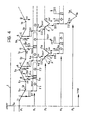
- Figure 1 is a perspective view of a line of presses in which a plurality of robots are used between the presses,
- Figure 2 is a partial elevation of the line of Figure 1,
- Figure 3 is a block diagram showing the equipment according to the invention, and
- Figure 4 is a graph showing the operating principle of the equipment according to the invention.
- Figures 1 and 2 show a line of presses P1, P2, P3, P4, P5, P6, and P7, generally indicated 1, which will carry out a succession of drawing, blanking and perforating operations, etc. on sheet-metal elements which are advanced along the line in order to produce motor-vehicle bodywork components. The line includes a plurality of robots R1, R2, R3, R4, R5, and R6 between the presses for transferring the pieces from one press to another. The structures of the presses P1-P7 are not described in detail since these structures may be of any known type and do not fall within the scope of the present invention. For the purposes of an understanding of the invention, however, it is important to mention the fact that each press includes a movable device M which is movable vertically between an inoperative, raised position and an operative, lowered position. Obviously, however, the invention can also be applied to lines of machines other than the presses.
- The robots R1-R6 shown between the presses in the appended drawings are of the type which is the subject of Italian Utility Model No. IT-U-O 195 537 and the corresponding foreign patent documents mentioned above. The structure of the robot is not described in detail herein since it does not fall within the scope of the present invention and, moreover, because the invention also applies to lines which use robots with different structures. A brief description of the robot which forms the subject of the patent documents mentioned above and which is used between the presses is provided here solely to enable the description which follows to be understood. With reference to Figure 2, each robot R1-R6 comprises a
fixed base structure 1 situated at a point intermediate two successive presses, a support platform 2 mounted on thebase structure 1 for rotation about avertical axis 3, alower body 4 mounted on the base platform 2 for rotation about avertical axis 5 spaced from theaxis 3, a forearm 6 articulated to thelower body 4 about ahorizontal axis 7, an arm 8 articulated to the forearm 6 about ahorizontal axis 9 and aterminal part 10 mounted on the end of the arm 8 for rotation about thelongitudinal axis 11 of the arm and having an articulatedwrist 12 carrying a piece-gripping member of any known type, for example, of the type with suction cups (not shown). For safety reasons, the region between each pair of successive presses, in which a respective robot works, is protected byrailings 13. - Finally, the line shown in Figures 1 and 2 includes a loading robot C and an unloading robot S upstream and downstream of the line respectively. The structures of the robots C, S are likewise not described below since they may be of any known type and do not fall within the scope of the present invention.
- Figure 3 of the appended drawings shows schematically the equipment according to the invention with reference to a station of the
line 1, that is, a portion of theline 1 including a between-press robot Ri, the press Pi situated immediately upstream of the robot Ri and the press P (i + 1) situated immediately downstream of the robot. - In known manner, each of the two presses and the robot has a respective on-board programmable logic control (PLC) indicated 12, 13 and 14 respectively for the upstream press, for the robot, and for the downstream press. The PLCs 12, 13, 14 govern the presses and the robot.
- The robot also has a movement control system (MCS) constituted by a processor which can exchange data with the
PLC 13 through the line. ThePLC 13 can exchange data withsimilar robot PLCs output lines robot PLC 13 also exchanges data with a control PLC of the station 23 by means of an input-output line 24 and with thePLCs 12, 14 by means of input/output lines similar PLCs output lines - Sensor means SP are associated with each press for emitting a signal when the movable device of the press is situated at one or more predetermined points in its cycle of reciprocating movement as will be described in more detail below. The sensor means may be of any known type. They may, for example, be constituted by mechanical sensor means adapted to cooperate with a movable part whose movement is linked to the movement of the movable device of the press. Alternatively, they may be constituted by electronic sensor means, for example for detecting the angular position of a rotary shaft which drives the movable device of the press.
- As another alternative, the means could be constituted by a sensor for detecting a parameter whose value is linked to the operating cycle of the press (for example a time, a temperature, etc.). The sensor means are not described in detail below since they have a known structure which does not fall within the scope of the present invention. Moreover, the elimination of these details from the drawings and from the description makes the latter more easily and readily understood.
- Sensor means SR, of the type indicated above, are also associated with the robot for detecting when the piece-gripping member carried by the
wrist 12 of the robot is situated in one or more predetermined positions of its cycle of movement. - The various devices shown in Figure 3 are arranged to carry out a sequence of steps which is described in detail below with reference to Figure 4.
- In the particular embodiment illustrated, when each robot is inoperative, it is in a waiting position (see Figure 2) facing the downstream press. When a given robot is brought into operation, it moves from this rest position to a first position which corresponds to the picking-up of a piece from the press upstream, then from the first position to a second position which corresponds to the deposition of the piece picked up in the press downstream, and then from the second position back to the rest position. This succession of movements is repeated cyclically, the robot stopping in the rest position for a predetermined time between one cycle and the next. As regards the presses in the line, however, when the line is running the movable device of each press moves cyclically between its inoperative, raised position and its operative, lowered position without pauses, except in the event of an emergency.
- Figure 4 of the appended drawings shows a graph representing the operating cycles of the presses P1, P2 and P3 and of the robots R1 and R2 in the line, the operation of the remaining presses and robots in the line being deducible from the following description with reference to the graphs illustrated.
- In Figure 4, the line l shown at the top represents a starting or start signal for the first press P1 in the line.
- At the instant t₀, this signal causes the press P1 to start. The operating cycle of the press is illustrated by the second line from the top in Figure 4. In the embodiment illustrated, the press P1 is of the type in which the movable device comprises a sheet hold-down appliance which is movable between a raised, inoperative position and a lowered, operative position and a punch which travels with the hold-down appliance along the portion of its path between the inoperative position and the operative position of the hold-down appliance, after which the punch can descend further to effect the drawing of a sheet-metal panel arranged in the press. With reference to the graph of Figure 4, after the start signal has been given at the instant t₀, the movable device of the press P1, comprising the punch and the hold-down appliance starts to descend from the inoperative raised position at the instant t₁. At the instant t₂, the hold-down appliance has reached its lowered, operative position. After this instant the punch continues to descend until it reaches its operative, lowered position, which occurs at the instant t₃. After this instant, the movable device returns upwardly until it reaches its inoperative, raised position at the instant t₄, after which the cycle is repeated in an identical manner.
- According to the present invention, once the start signal has been given at the instant t₀, the
PLC 12 of the first press P1 in the line causes the device of that press to move cyclically with a predetermined, basic cycle frequency which is intended to govern the operating cycles of all the remaining presses and of all the robots in the line. In other words, the rate of operation of the first press P1 in the line is used as a reference or "clock" for the whole line. Naturally, the rates of operation of all the machines in the line, are taken into account in the selection of this rate of operation so that it is not slower than any of them. - The start signal for the robot R1 situated immediately downstream of the press P1 is generated with reference to a predetermined point in the cycle of the press P1. More particularly, the signal which starts the robot R1 is given in correspondence with a point C in the cycle of the press P1. When the sensor means SP associated with the press P1 detect that the cycle of the press has reached the point C, they emit a signal which is received by the
PLC 12 of the press and transmitted thereby to the robot PLC 13 (Figure 3) which starts the robot R1 after a delay D1 (Figure 4) from the instant at which the cycle of the press passes through the point C. - With reference to Figure 4, the robot R1 is started at the instant tr1. At this instant, the robot is in its rest position facing the press P2. During a first stage in its cycle, the gripping member of the robot moves towards the press P1 (as shown symbolically by the arrow F1 in Figure 4). The robot thus reaches its first position, in correspondence with the press P1, where it can pick up a worked piece (that part of the graph of the cycle of R1 shown by a broken line) after which it moves towards its second position (arrow F2) and thence back to its rest position, where it stops. The point C in the cycle of the press P1, at which the press calls on the robot R1, is selected so that, when the robot reaches the press P1, the press is sure to be open and the robot can pick up the piece worked thereby without the need for intermediate stops. In order to take account of possible emergency situations, in each case an OK signal, that is a signal for enabling the robot R1 to enter the press, is generated at a point B in the cycle of the press P1 (the reaching of which is indicated by the sensor means SP). Again for safety reasons, the robot R1 carries out a check with the press P1 at an instant tr2, as shown schematically by the broken arrow of Figure 4, to confirm that the press is open. This check is carried out by the robot PLC through the input-
output lines - At an instant tr3 at which the robot reaches its working position at the press P1, another signal is generated which, after a delay D3, gives rise to an OK, or enabling, signal for the loading of a new piece into the press P1. Again, for the same reason, the press carries out a check with the robot at a point A in the cycle of the press P1, which is reached after the instant t₄, to confirm that the robot has moved away from its working position at the press. After the point A in the cycle has been reached, the steps described above are repeated cyclically.
- At the start of the second cycle of the robot R1, at the instant indicated tr4, the sensor means SR generate a signal which starts a second press P2 in the line after a delay D2. This press is of the type including a single striking hammer which can be moved between a first, inoperative, raised position and an operative, lowered position. At the instant t₁₀, the striking mass starts to descend, its operative, lowered position being reached at the instant t₁₁, after which the striking mass rises again until it reaches its inoperative, raised position at the instant t₁₂. At an instant tr5, the sensor means SR associated with the robot R1 generate an enabling signal for the operation of the press P2 which ensures that the robot R1 has moved away from its operating position at the press P2 when the movable device of that press is lowered. At an instant after the instant t₁₀, the press in turn carries out a check with the robot R1 in order to verify that the robot has moved away. At a point C in the cycle of the press P2, the reaching of which is detected by the sensor means SP associated with that press, a signal is generated which starts the robot R2 situated downstream of the press P2 after a delay D1. At a point B in a cycle of the press P2, the press gives a signal for enabling the operation of the robot R2, which ensures that the press is open when the robot reaches its working position at the press P2. The robot R2 in turn carries out a check with the press P2 at a instant Tr6 to confirm that the press is open. When it reaches its working position at the press upstream, the robot R2 also generates a signal which, with a delay D3, gives the OK to the robot R1 to ensure that there cannot be a collision between the robots R1 and R2 at the press P2. For the same reason, the robot R1 makes a check with the robot R2 (which is affected by means of an exchange of data between the MCS processors associated with the robots) to confirm that the robot R2 has moved away from the press P2 when the robot R1 is about to arrive at that press.
- In a similar manner to that described above, the robot R2 emits a signal at the start of its second cycle to start the press P3 after a delay D2. The operating cycle of this press is used as a reference for the operating cycle of the robot R3 and so on, in a cascade process, until all the robots and all the presses in the line are covered.
- Any anomaly at a station is communicated by the PLC 23 to the other station PLCs in order to stop the line if necessary.
- Naturally, the principle of the invention remaining the same, the details of construction and forms of embodiment may be varied widely with respect to those described and illustrated purely by way of example, without thereby departing from the scope of the present invention.
Claims (6)
- Equipment for controlling the operation of a line (1) of machines (P1-P7), particularly presses, which are intended to perform a succession of operations on pieces which are advanced along the line (1), the line also including a plurality of programmable manipulator robots (R1-R6) interposed between the machines (P1-P7) for transferring the pieces from one machine to another, each machine (P1-P7) having a device (M) which is movable between an operative position for carrying out a certain operation on a piece arranged in the machine and an inoperative position in which a piece to be worked can be deposited in the machine or a piece worked by the machine can be picked up; each manipulator robot (R1-R6) including a gripping member which is movable between a first position in which it can grip a piece situated in the machine immediately upstream of the robot and a second position in which it can deposit the piece it has gripped in the machine immediately downstream of the robot, the equipment being characterised in that it comprises:- control means (12, 18, 23) for the first machine (P1) in the line (1) which are arranged to cause a cyclic movement of the movable device (M) of the first machine (P1) between its inoperative position and its operative position at a predetermined, basic cycle frequency which will govern the operating cycles of all the rest of the machines (P2-P7) and of all the robots (R1-R6) in the line (1) in cascade,- sensor means (SP) associated with the first machine (P1) and with each subsequent machine (P2-P7) in the line (1) for emitting a signal each instant the respective machine is at a predetermined point (C) in its operating cycle,- control means (13) associated with each manipulator robot (R1-R6) in the line (1) for starting the respective manipulator robot as a result of the emission of the signal by the sensor means (SP) associated with the machine immediately upstream of the manipulator robot, causing the gripping member (12) of the manipulator robot to move cyclically from a rest position to the first position, from the first position to the second position and from the second position back to the rest position in an operating cycle which is in phase with the operating cycle of the machine immediately upstream of the manipulator robot,- sensor means (SR) associated with each manipulator robot (R1-R6) in the line (1) for emitting a signal each instant the gripping member (12) of the respective robot is at a predetermined point in its cycle, and- control means (15, 17, 16, 23) associated with each machine downstream of the first machine in the line for starting a cyclic movement of the movable device of the respective machine between its operative position and its inoperative position as a result of the emission of the signal by the sensor means (SR) associated with the manipulator robot which is immediately upstream of that machine, so that the operating cycle of each machine downstream of the first machine (P1) is in phase with the operating cycle of the manipulator robot situated immediately upstream.
- Equipment according to Claim 1, characterised in that each manipulator robot (R1-R6) is started with a predetermined delay (D1) after the machine upstream of that robot has reached the predetermined point (C) in its cycle.
- Equipment according to Claim 1, characterised in that each machine (P2-P7) downstream of the first machine (P1) is started with a predetermined delay (D2) after the robot upstream of that machine has reached the predetermined point in its cycle.
- Equipment according to Claim 1, characterised in that the sensor means (SP) associated with each machine are arranged to detect the reaching of a second point (B) and of a third point (A) in the cycle of the machine and these points are used as references for avoiding collisions of the machine with the robot downstream of the machine when the robot arrives at its first working position at the machine and when the movable device of the machine moves towards its operative position.
- Equipment according to Claim 1, characterised in that the sensor means (SR) associated with each robot are arranged to detect the reaching of one or more further points in the operating cycle of the robot and these are used as references for avoiding collisions of the robot with the machine upstream and with the robot upstream thereof.
- A method for controlling the operation of a line (1) including a plurality of machines (P1-P7), particularly presses, which are intended to perform a succession of operations on pieces which are advanced along the line (1), the line also including a plurality of programmable manipulator robots (R1-R6) interposed between the machines (P1-P7) for transferring the pieces from one machine to another, each machine (P1-P7) having a device (M) which is movable between an operative position for carrying out a certain operation on a piece situated in the machine and an inoperative position in which a piece to be worked can be deposited in the machine or a piece worked by the machine can be picked up; each manipulator robot (R1-R6) including a gripping member (12) which is movable between a first position in which it can grip a piece situated in the machine immediately upstream of the robot and a second position in which it can deposit the piece it has gripped in the machine immediately downstream of the robot,
the method being characterised in that it comprises the following steps:- causing a cyclic movement of the movable device (M) of the first machine (P1) in the line (1) between its inoperative position and its operative position at a predetermined, basic cycle frequency which will govern the operating cycles of all the rest of the machines (P2-P7) and of all the robots (R1-R6) in the line (1),- producing a signal each instant each given machine in the line is at a predetermined point (C) in its operating cycle,- starting each given manipulator robot as a result of the emission of the signal corresponding to the reaching of the predetermined point (C) in the operating cycle of the press situated immediately upstream of the manipulator robot, moving the gripping member of the manipulator cyclically from its rest position to its first position, from its first position to its second position and from its second position back to its rest position in an operating cycle which is in phase with the operating cycle of the machine situated immediately upstream,- emitting a signal each instant the gripping member of a given manipulator robot is at a predetermined point in its cycle, and- starting a cyclic movement of the movable device (M) of each given machine between its operative position and its inoperative position as a result of the emission of the signal corresponding to the reaching of the predeterminated point in the operating cycle of the robot situated immediately upstream so that the operating cycle of each machine downstream of the first machine is in phase with the operating cycle of the robot immediately upstream.
Applications Claiming Priority (2)
| Application Number | Priority Date | Filing Date | Title |
|---|---|---|---|
| IT06813589A IT1237709B (en) | 1989-12-20 | 1989-12-20 | APPARATUS AND PROCEDURE FOR CHECKING THE OPERATION OF A LINE OF OPERATING MACHINES, IN PARTICULAR PRESSES. |
| IT6813589 | 1989-12-20 |
Publications (3)
| Publication Number | Publication Date |
|---|---|
| EP0434632A2 true EP0434632A2 (en) | 1991-06-26 |
| EP0434632A3 EP0434632A3 (en) | 1993-11-10 |
| EP0434632B1 EP0434632B1 (en) | 1996-03-13 |
Family
ID=11308089
Family Applications (1)
| Application Number | Title | Priority Date | Filing Date |
|---|---|---|---|
| EP90830517A Expired - Lifetime EP0434632B1 (en) | 1989-12-20 | 1990-11-13 | Equipment and method for controlling the operation of a line of machines, particularly presses |
Country Status (7)
| Country | Link |
|---|---|
| US (1) | US5150451A (en) |
| EP (1) | EP0434632B1 (en) |
| JP (1) | JPH0437424A (en) |
| KR (1) | KR100208506B1 (en) |
| DE (1) | DE69025879T2 (en) |
| ES (1) | ES2086396T3 (en) |
| IT (1) | IT1237709B (en) |
Cited By (6)
| Publication number | Priority date | Publication date | Assignee | Title |
|---|---|---|---|---|
| EP1615090A1 (en) * | 2004-07-10 | 2006-01-11 | FAGOR, S.Coop | Synchronized control system of a line of machines, particularly presses |
| EP1705541A2 (en) | 2005-03-23 | 2006-09-27 | Kawasaki Jukogyo Kabushiki Kaisha | Robot controller and robot control method |
| WO2007091964A2 (en) * | 2006-02-06 | 2007-08-16 | Abb Research Ltd. | Press line system and method |
| EP1815972A3 (en) * | 2006-02-06 | 2007-10-10 | Abb Research Ltd. | Press line system and method |
| US7805973B2 (en) | 2006-02-06 | 2010-10-05 | Abb Research Ltd. | Mechanical press drive system |
| AT522991A1 (en) * | 2019-10-10 | 2021-04-15 | Trumpf Maschinen Austria Gmbh & Co Kg | Process for the transport and / or handling of components |
Families Citing this family (10)
| Publication number | Priority date | Publication date | Assignee | Title |
|---|---|---|---|---|
| AU6014896A (en) * | 1995-06-13 | 1997-01-09 | Toyo Kohan Co. Ltd. | Interference preventing method for industrial robots |
| DE112004000097B4 (en) * | 2003-05-01 | 2015-08-20 | Komatsu Ltd. | Tandem press line, operation control method for tandem press line, and workpiece transport device for tandem press line |
| US7127931B1 (en) | 2004-11-23 | 2006-10-31 | Honda Motor Co., Ltd. | Tandem press shuttle area isolation gate system and method of use |
| DE112017004812T5 (en) * | 2016-09-26 | 2019-06-06 | Fanuc America Corporation | AUTOMATIC SYNCHRONIZATION OF PRESS MACHINES AND ROBOTS |
| CN107159803A (en) * | 2017-05-23 | 2017-09-15 | 广州市铮宝精密机械有限公司 | Pressing robot automatic loading and unloading system |
| CN110125244B (en) * | 2018-02-08 | 2020-08-14 | 上海一芯智能科技有限公司 | Multi-stamping manipulator linkage control method and system and controller |
| IT201800004086A1 (en) * | 2018-03-29 | 2019-09-29 | Fca Italy Spa | PROCEDURE FOR THE COMMISSIONING AND / OR RECONFIGURATION OF AN INDUSTRIAL PLANT, IN PARTICULAR FOR THE PRODUCTION OF MOTOR VEHICLES OR THEIR SUB-GROUPS |
| KR102116929B1 (en) * | 2019-09-24 | 2020-05-29 | 제영남 | Manufacturing method of seat spring bracket |
| CN114309212B (en) * | 2021-12-30 | 2024-06-28 | 南京艾程自动化科技有限公司 | Full-automatic stamping production line |
| CN114393129B (en) * | 2021-12-31 | 2024-01-30 | 珠海格力智能装备有限公司 | Feeding and discharging control method and production line for inner container of slow stewing pot |
Citations (8)
| Publication number | Priority date | Publication date | Assignee | Title |
|---|---|---|---|---|
| US3758835A (en) * | 1971-11-01 | 1973-09-11 | Dixon Automatic Tool | Standardized control sections for machine control systems |
| FR2267199A1 (en) * | 1974-04-09 | 1975-11-07 | Schuler Gmbh L | |
| GB2059637A (en) * | 1979-05-09 | 1981-04-23 | Polygraph Leipzig | Printing machine |
| US4293914A (en) * | 1979-05-24 | 1981-10-06 | Nguyen Van Trang | Automatic control system for carwash installations |
| EP0047056A2 (en) * | 1980-08-29 | 1982-03-10 | Danly Machine Corporation | Power press arrangement |
| EP0084574A1 (en) * | 1981-08-04 | 1983-08-03 | Fanuc Ltd. | Industrial robot control system |
| EP0134256A1 (en) * | 1983-08-01 | 1985-03-20 | The Cross Company | Transfer machine control |
| US4661040A (en) * | 1983-12-12 | 1987-04-28 | Comau S.P.A. | Manipulator robot, more particularly for transferring sheet metal elements from a pressing station to the next pressing station of a pressing line |
Family Cites Families (7)
| Publication number | Priority date | Publication date | Assignee | Title |
|---|---|---|---|---|
| JPS57103747A (en) * | 1980-12-20 | 1982-06-28 | Hitachi Kiden Kogyo Ltd | Automatic press device |
| JPS63194832A (en) * | 1987-02-06 | 1988-08-12 | Mitsubishi Motors Corp | Work transfer device |
| JP2507742B2 (en) * | 1987-06-09 | 1996-06-19 | マツダ株式会社 | Work transfer device |
| US4894908A (en) * | 1987-08-20 | 1990-01-23 | Gmf Robotics Corporation | Method for automated assembly of assemblies such as automotive assemblies and system utilizing same |
| US4870592A (en) * | 1988-02-01 | 1989-09-26 | Lampi Wayne J | Manufacturing system with centrally disposed dynamic buffer region |
| US4990839A (en) * | 1988-12-09 | 1991-02-05 | Schonlau William J | Modular robotic system |
| JPH0310780A (en) * | 1989-06-05 | 1991-01-18 | Mitsubishi Electric Corp | Industrial robot device |
-
1989
- 1989-12-20 IT IT06813589A patent/IT1237709B/en active IP Right Grant
-
1990
- 1990-11-13 DE DE69025879T patent/DE69025879T2/en not_active Expired - Fee Related
- 1990-11-13 ES ES90830517T patent/ES2086396T3/en not_active Expired - Lifetime
- 1990-11-13 EP EP90830517A patent/EP0434632B1/en not_active Expired - Lifetime
- 1990-12-17 US US07/628,779 patent/US5150451A/en not_active Expired - Lifetime
- 1990-12-17 KR KR1019900020800A patent/KR100208506B1/en not_active IP Right Cessation
- 1990-12-19 JP JP2403624A patent/JPH0437424A/en active Pending
Patent Citations (8)
| Publication number | Priority date | Publication date | Assignee | Title |
|---|---|---|---|---|
| US3758835A (en) * | 1971-11-01 | 1973-09-11 | Dixon Automatic Tool | Standardized control sections for machine control systems |
| FR2267199A1 (en) * | 1974-04-09 | 1975-11-07 | Schuler Gmbh L | |
| GB2059637A (en) * | 1979-05-09 | 1981-04-23 | Polygraph Leipzig | Printing machine |
| US4293914A (en) * | 1979-05-24 | 1981-10-06 | Nguyen Van Trang | Automatic control system for carwash installations |
| EP0047056A2 (en) * | 1980-08-29 | 1982-03-10 | Danly Machine Corporation | Power press arrangement |
| EP0084574A1 (en) * | 1981-08-04 | 1983-08-03 | Fanuc Ltd. | Industrial robot control system |
| EP0134256A1 (en) * | 1983-08-01 | 1985-03-20 | The Cross Company | Transfer machine control |
| US4661040A (en) * | 1983-12-12 | 1987-04-28 | Comau S.P.A. | Manipulator robot, more particularly for transferring sheet metal elements from a pressing station to the next pressing station of a pressing line |
Cited By (11)
| Publication number | Priority date | Publication date | Assignee | Title |
|---|---|---|---|---|
| EP1615090A1 (en) * | 2004-07-10 | 2006-01-11 | FAGOR, S.Coop | Synchronized control system of a line of machines, particularly presses |
| EP1705541A2 (en) | 2005-03-23 | 2006-09-27 | Kawasaki Jukogyo Kabushiki Kaisha | Robot controller and robot control method |
| EP1705541A3 (en) * | 2005-03-23 | 2008-08-06 | Kawasaki Jukogyo Kabushiki Kaisha | Robot controller and robot control method |
| US7729804B2 (en) | 2005-03-23 | 2010-06-01 | Kawasaki Jukogyo Kabushiki Kaisha | Robot controller and robot control method for synchronous operation and adjusting robot movement based on two movement times |
| WO2007091964A2 (en) * | 2006-02-06 | 2007-08-16 | Abb Research Ltd. | Press line system and method |
| EP1815972A3 (en) * | 2006-02-06 | 2007-10-10 | Abb Research Ltd. | Press line system and method |
| WO2007091964A3 (en) * | 2006-02-06 | 2007-11-01 | Abb Research Ltd | Press line system and method |
| US7805973B2 (en) | 2006-02-06 | 2010-10-05 | Abb Research Ltd. | Mechanical press drive system |
| US8302452B2 (en) | 2006-02-06 | 2012-11-06 | Abb Research Ltd. | Mechanical press drive system and method |
| AT522991A1 (en) * | 2019-10-10 | 2021-04-15 | Trumpf Maschinen Austria Gmbh & Co Kg | Process for the transport and / or handling of components |
| AT522991B1 (en) * | 2019-10-10 | 2022-02-15 | Trumpf Maschinen Austria Gmbh & Co Kg | Process for transporting and/or handling components |
Also Published As
| Publication number | Publication date |
|---|---|
| KR100208506B1 (en) | 1999-07-15 |
| KR910011442A (en) | 1991-08-07 |
| DE69025879T2 (en) | 1996-09-05 |
| EP0434632B1 (en) | 1996-03-13 |
| IT8968135A0 (en) | 1989-12-20 |
| EP0434632A3 (en) | 1993-11-10 |
| DE69025879D1 (en) | 1996-04-18 |
| ES2086396T3 (en) | 1996-07-01 |
| US5150451A (en) | 1992-09-22 |
| IT1237709B (en) | 1993-06-15 |
| JPH0437424A (en) | 1992-02-07 |
Similar Documents
| Publication | Publication Date | Title |
|---|---|---|
| EP0434632B1 (en) | Equipment and method for controlling the operation of a line of machines, particularly presses | |
| EP0091663B1 (en) | Apparatus for controlling operation of an industrial robot | |
| JP2532533Y2 (en) | Interlock device for work transfer system | |
| US4314185A (en) | Control circuit for an automated press system | |
| US5525023A (en) | Chip component supply apparatus | |
| CN107030180A (en) | A kind of keel hole-punching method and device and keel cold-rolling mill | |
| EP1110854B1 (en) | Robot system synchronized with conveyor speed and car seat providing method using such a robot system | |
| CN112830228B (en) | Truss robot double-manipulator multipoint grabbing automatic feeding system and control method thereof | |
| CN110316559A (en) | A kind of sleeper fastening classification delivery method and system | |
| JP3528196B2 (en) | Robot system synchronized with press machine | |
| Weston et al. | Universal machine control system primitives for modular distributed manipulator systems | |
| CN108581471A (en) | Gear handball automatic assembling production line | |
| CN112657860A (en) | Automatic queuing system and queuing method | |
| JP3423141B2 (en) | Synchronization loss recovery device | |
| CN107932501A (en) | Stacking machine arranges the control method of case manipulator | |
| CN217035538U (en) | Full-automatic assembly production line for magnetic circuit components | |
| EP0781249B1 (en) | Method and arrangement for positioning of articles on conveying belts | |
| JP3783253B2 (en) | Tuning control method for multiple robots | |
| CN217263146U (en) | Material grabbing and positioning manipulator suitable for assembling magnetic circuit assembly | |
| JP2534052B2 (en) | Work transfer device | |
| CN211969934U (en) | Full-automatic yard vanning equipment of sweeping of PCB board based on six manipulators | |
| CN107598561A (en) | A kind of jump ring buckle of automobile door plate and the assembling monitoring method of screw | |
| Petersson | An integrated robot vision system for industrial use | |
| CN109328126A (en) | Filming apparatus and camera system | |
| CN111318690A (en) | Pressing system with automatic mold transfer function and using method thereof |
Legal Events
| Date | Code | Title | Description |
|---|---|---|---|
| PUAI | Public reference made under article 153(3) epc to a published international application that has entered the european phase |
Free format text: ORIGINAL CODE: 0009012 |
|
| AK | Designated contracting states |
Kind code of ref document: A2 Designated state(s): DE ES FR GB SE |
|
| PUAL | Search report despatched |
Free format text: ORIGINAL CODE: 0009013 |
|
| AK | Designated contracting states |
Kind code of ref document: A3 Designated state(s): DE ES FR GB SE |
|
| 17P | Request for examination filed |
Effective date: 19940219 |
|
| 17Q | First examination report despatched |
Effective date: 19950502 |
|
| GRAA | (expected) grant |
Free format text: ORIGINAL CODE: 0009210 |
|
| AK | Designated contracting states |
Kind code of ref document: B1 Designated state(s): DE ES FR GB SE |
|
| REF | Corresponds to: |
Ref document number: 69025879 Country of ref document: DE Date of ref document: 19960418 |
|
| ET | Fr: translation filed | ||
| REG | Reference to a national code |
Ref country code: ES Ref legal event code: FG2A Ref document number: 2086396 Country of ref document: ES Kind code of ref document: T3 |
|
| PLBE | No opposition filed within time limit |
Free format text: ORIGINAL CODE: 0009261 |
|
| STAA | Information on the status of an ep patent application or granted ep patent |
Free format text: STATUS: NO OPPOSITION FILED WITHIN TIME LIMIT |
|
| 26N | No opposition filed | ||
| PGFP | Annual fee paid to national office [announced via postgrant information from national office to epo] |
Ref country code: SE Payment date: 20001006 Year of fee payment: 11 |
|
| PG25 | Lapsed in a contracting state [announced via postgrant information from national office to epo] |
Ref country code: SE Free format text: LAPSE BECAUSE OF NON-PAYMENT OF DUE FEES Effective date: 20011114 |
|
| REG | Reference to a national code |
Ref country code: GB Ref legal event code: IF02 |
|
| EUG | Se: european patent has lapsed |
Ref document number: 90830517.0 |
|
| PGFP | Annual fee paid to national office [announced via postgrant information from national office to epo] |
Ref country code: GB Payment date: 20041014 Year of fee payment: 15 |
|
| PG25 | Lapsed in a contracting state [announced via postgrant information from national office to epo] |
Ref country code: GB Free format text: LAPSE BECAUSE OF NON-PAYMENT OF DUE FEES Effective date: 20051113 |
|
| GBPC | Gb: european patent ceased through non-payment of renewal fee |
Effective date: 20051113 |
|
| PGFP | Annual fee paid to national office [announced via postgrant information from national office to epo] |
Ref country code: ES Payment date: 20061003 Year of fee payment: 17 |
|
| PGFP | Annual fee paid to national office [announced via postgrant information from national office to epo] |
Ref country code: DE Payment date: 20061025 Year of fee payment: 17 |
|
| PGFP | Annual fee paid to national office [announced via postgrant information from national office to epo] |
Ref country code: FR Payment date: 20061130 Year of fee payment: 17 |
|
| PG25 | Lapsed in a contracting state [announced via postgrant information from national office to epo] |
Ref country code: DE Free format text: LAPSE BECAUSE OF NON-PAYMENT OF DUE FEES Effective date: 20080603 |
|
| REG | Reference to a national code |
Ref country code: FR Ref legal event code: ST Effective date: 20080930 |
|
| REG | Reference to a national code |
Ref country code: ES Ref legal event code: FD2A Effective date: 20071114 |
|
| PG25 | Lapsed in a contracting state [announced via postgrant information from national office to epo] |
Ref country code: FR Free format text: LAPSE BECAUSE OF NON-PAYMENT OF DUE FEES Effective date: 20071130 Ref country code: ES Free format text: LAPSE BECAUSE OF NON-PAYMENT OF DUE FEES Effective date: 20071114 |