EP0434503A1 - Kohärentes Impulsradarsystem und -verfahren zum Detektieren eines Ziels mit kurzzeitigen starken Reflexionen - Google Patents
Kohärentes Impulsradarsystem und -verfahren zum Detektieren eines Ziels mit kurzzeitigen starken Reflexionen Download PDFInfo
- Publication number
- EP0434503A1 EP0434503A1 EP90403543A EP90403543A EP0434503A1 EP 0434503 A1 EP0434503 A1 EP 0434503A1 EP 90403543 A EP90403543 A EP 90403543A EP 90403543 A EP90403543 A EP 90403543A EP 0434503 A1 EP0434503 A1 EP 0434503A1
- Authority
- EP
- European Patent Office
- Prior art keywords
- thresholds
- maximum amplitude
- pulses
- channels
- rank
- Prior art date
- Legal status (The legal status is an assumption and is not a legal conclusion. Google has not performed a legal analysis and makes no representation as to the accuracy of the status listed.)
- Withdrawn
Links
Images


Classifications
-
- G—PHYSICS
- G01—MEASURING; TESTING
- G01S—RADIO DIRECTION-FINDING; RADIO NAVIGATION; DETERMINING DISTANCE OR VELOCITY BY USE OF RADIO WAVES; LOCATING OR PRESENCE-DETECTING BY USE OF THE REFLECTION OR RERADIATION OF RADIO WAVES; ANALOGOUS ARRANGEMENTS USING OTHER WAVES
- G01S13/00—Systems using the reflection or reradiation of radio waves, e.g. radar systems; Analogous systems using reflection or reradiation of waves whose nature or wavelength is irrelevant or unspecified
- G01S13/02—Systems using reflection of radio waves, e.g. primary radar systems; Analogous systems
- G01S13/06—Systems determining position data of a target
- G01S13/08—Systems for measuring distance only
- G01S13/10—Systems for measuring distance only using transmission of interrupted, pulse modulated waves
- G01S13/26—Systems for measuring distance only using transmission of interrupted, pulse modulated waves wherein the transmitted pulses use a frequency- or phase-modulated carrier wave
- G01S13/28—Systems for measuring distance only using transmission of interrupted, pulse modulated waves wherein the transmitted pulses use a frequency- or phase-modulated carrier wave with time compression of received pulses
- G01S13/284—Systems for measuring distance only using transmission of interrupted, pulse modulated waves wherein the transmitted pulses use a frequency- or phase-modulated carrier wave with time compression of received pulses using coded pulses
- G01S13/288—Systems for measuring distance only using transmission of interrupted, pulse modulated waves wherein the transmitted pulses use a frequency- or phase-modulated carrier wave with time compression of received pulses using coded pulses phase modulated
-
- G—PHYSICS
- G01—MEASURING; TESTING
- G01S—RADIO DIRECTION-FINDING; RADIO NAVIGATION; DETERMINING DISTANCE OR VELOCITY BY USE OF RADIO WAVES; LOCATING OR PRESENCE-DETECTING BY USE OF THE REFLECTION OR RERADIATION OF RADIO WAVES; ANALOGOUS ARRANGEMENTS USING OTHER WAVES
- G01S13/00—Systems using the reflection or reradiation of radio waves, e.g. radar systems; Analogous systems using reflection or reradiation of waves whose nature or wavelength is irrelevant or unspecified
- G01S13/02—Systems using reflection of radio waves, e.g. primary radar systems; Analogous systems
- G01S13/06—Systems determining position data of a target
- G01S13/08—Systems for measuring distance only
- G01S13/10—Systems for measuring distance only using transmission of interrupted, pulse modulated waves
- G01S13/22—Systems for measuring distance only using transmission of interrupted, pulse modulated waves using irregular pulse repetition frequency
- G01S13/225—Systems for measuring distance only using transmission of interrupted, pulse modulated waves using irregular pulse repetition frequency with cyclic repetition of a non-uniform pulse sequence, e.g. staggered PRF
-
- G—PHYSICS
- G01—MEASURING; TESTING
- G01S—RADIO DIRECTION-FINDING; RADIO NAVIGATION; DETERMINING DISTANCE OR VELOCITY BY USE OF RADIO WAVES; LOCATING OR PRESENCE-DETECTING BY USE OF THE REFLECTION OR RERADIATION OF RADIO WAVES; ANALOGOUS ARRANGEMENTS USING OTHER WAVES
- G01S13/00—Systems using the reflection or reradiation of radio waves, e.g. radar systems; Analogous systems using reflection or reradiation of waves whose nature or wavelength is irrelevant or unspecified
- G01S13/02—Systems using reflection of radio waves, e.g. primary radar systems; Analogous systems
- G01S13/06—Systems determining position data of a target
- G01S13/08—Systems for measuring distance only
- G01S13/10—Systems for measuring distance only using transmission of interrupted, pulse modulated waves
- G01S13/30—Systems for measuring distance only using transmission of interrupted, pulse modulated waves using more than one pulse per radar period
-
- G—PHYSICS
- G01—MEASURING; TESTING
- G01S—RADIO DIRECTION-FINDING; RADIO NAVIGATION; DETERMINING DISTANCE OR VELOCITY BY USE OF RADIO WAVES; LOCATING OR PRESENCE-DETECTING BY USE OF THE REFLECTION OR RERADIATION OF RADIO WAVES; ANALOGOUS ARRANGEMENTS USING OTHER WAVES
- G01S13/00—Systems using the reflection or reradiation of radio waves, e.g. radar systems; Analogous systems using reflection or reradiation of waves whose nature or wavelength is irrelevant or unspecified
- G01S13/02—Systems using reflection of radio waves, e.g. primary radar systems; Analogous systems
- G01S13/50—Systems of measurement based on relative movement of target
- G01S13/52—Discriminating between fixed and moving objects or between objects moving at different speeds
- G01S13/522—Discriminating between fixed and moving objects or between objects moving at different speeds using transmissions of interrupted pulse modulated waves
- G01S13/524—Discriminating between fixed and moving objects or between objects moving at different speeds using transmissions of interrupted pulse modulated waves based upon the phase or frequency shift resulting from movement of objects, with reference to the transmitted signals, e.g. coherent MTi
- G01S13/5246—Discriminating between fixed and moving objects or between objects moving at different speeds using transmissions of interrupted pulse modulated waves based upon the phase or frequency shift resulting from movement of objects, with reference to the transmitted signals, e.g. coherent MTi post processors for coherent MTI discriminators, e.g. residue cancellers, CFAR after Doppler filters
Definitions
- the present invention relates to a method and a coherent radar system with unambiguous pulses of distance for the detection of a target exhibiting lightnings of very short duration and of long period, in particular helicopters.
- Certain surveillance radars seek in particular to detect targets in agitation whose radar equivalent surface may be only large enough to be detectable only for moments of very short duration. This may be the case, for example, for helicopters that one wishes to recognize as such. Indeed, we know that an essential characteristic of helicopters, from the point of view of the radar equivalent surface, is that the blades of their main rotor provide a very significant equivalent surface only when they are in the vicinity of a perpendicular plane. to the radar-helicopter direction. This configuration is repeated periodically with a period of high value, for example of the order of twenty to one hundred milliseconds, but lasts only a very short time, giving rise for example to a "flash" of a duration of the order of 50 to 200 microseconds.
- a first solution envisaged is to use pulses with a high repetition frequency and, to resolve ambiguities in distance, successively emit bursts of pulses with different repetition periods.
- a disadvantage of this solution is that it greatly increases the time required to observe the target, which makes it almost impossible to track the target.
- a solution derived from this would consist in using interlaced bursts at low frequency of constant repetition (therefore unambiguously distance for the radar coverage envisaged), each burst using a different carrier frequency.
- this solution like the previous one, requires N transmitters and N receivers with different carrier frequencies, which implies complex, bulky and expensive equipment.
- the invention aims to remedy these drawbacks by starting from the observation that the blade flashes are rare in time and in distance because there are generally few helicopters in the field of radar surveillance. This means that partial ambiguities can be tolerated from a distance.
- the pulses of a periodic pattern will be differentiated by applying to them different phase modulations and preferably pseudo-orthogonal (with low intercorrelation) modulations, the modulation being coherent. for all of the pulses.
- One of the advantages of such a method is that a single transmitter and receiver can be used, the receiver being followed by N sub-receivers or signal processing channels corresponding to the various pulses.
- these pulses are separated by durations T1, T2 ... all different but close to the period Tm of the pattern divided by N.
- This average period Tm / N is chosen to be of the order of magnitude of the minimum duration of the flashes to detect.
- the period Tm of the pattern is chosen so that it corresponds to an ambiguity in distance greater than the distance coverage sought.
- Modulation laws are chosen in pseudo-orthogonal phase, that is to say having low values of intercorrelation function. This is important for the proper functioning of the system as will be seen below.
- a radar system using this principle according to the invention comprises only one transmitter, transmitting successive pulses at the same carrier frequency but with adequate phase modulation, and a single receiver followed by N signal processing channels each corresponding to a particular pulse compression channel, that is to say a pulse of the pattern.
- the filtering for elimination of parasitic echoes is carried out from pattern to pattern and therefore has the same efficiency as in an unambiguous radar of distance with periodic pulses.
- the radar system according to the invention presents partial ambiguities in distance. Indeed, as the phase modulation laws are not perfectly orthogonal (intercorrelation products not equal to zero), a blade flash echo corresponding to a particular pulse will give a main peak in the corresponding channel but also non-zero secondary peaks in other routes.
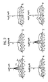
- FIG. 3 This is shown diagrammatically in FIG. 3 where is represented in A the ambiguity diagram of a sub-receptor (or processing channel) alone with its main peaks and in B the ambiguity diagram of a sub-receiver in the presence on the other, for example those corresponding to pulses 11 and 12.
- A the ambiguity diagram of a sub-receptor (or processing channel) alone with its main peaks
- B the ambiguity diagram of a sub-receiver in the presence on the other, for example those corresponding to pulses 11 and 12.
- We are then in the presence of secondary peaks spaced from T1 of the main peaks which correspond to partial ambiguities in distance.
- the secondary peaks are of sufficiently low amplitude to be eliminated by comparison of the amplitudes received at each instant in the various processing channels, as will be seen below. below.
- Diagram A represents what happens to the radar system during the emission of a pulse. All the processing channels are obscured not only during the duration Te of the transmitted pulse, for example 11, but also for a time. Taem of pre-emission and a time Tpe of post-emission. The reception time is therefore Trc.
- FIG. 5 shows the time diagram of a three-pulse pattern I1, I2, 13 (three pulses only for clarity of the figures).
- the duration of the pattern is Tm.
- Each pulse is separated from the next by a different spacing, respectively T1, T2 and T3.
- Each pulse defines an area of unobservability represented by hatching.
- Tq the duration of such a domain and we choose Tq as the time quantization step
- Ti the durations Ti (i equal to 1, 2 or 3) by numbers. If these numbers are suitably chosen, it can be seen from diagram B in FIG. 4 that it can be achieved that none of the domains of non-observability of each of the channels overlaps, except at the start of each pattern which is inevitable.
- Diagram C consequently represents the rate of observability of the distances D.
- the minimum rate of observability can be adjusted.
- FIG. 6 represents the diagram of a radar system implementing the principles mentioned above.
- the radar system comprises a common transmit-receive antenna 1 connected to a circulator 2.
- the transmitter connected to this circulator consists of an oscillator 3 at the carrier frequency F a , a phase modulator 4 and an amplifier 5.
- the wave supplied by the oscillator 3 is modulated in pulses and, inside each pulse, in phase under the control of a sequencer 6 which synchronizes the pulses and provides the appropriate modulation laws (codes).
- the circulator2 is also connected to unique reception means comprising the receiver 7 and the device 8 for the coherent elimination of clutter echoes and of the target body echo by linear filtering.
- a device can for example be a filter with autoregressive signal processing.
- This filter comprises in known manner a lattice filter of order 1 and a coefficient calculator a n-1 of the lattice filter.
- the calculation of the filtering coefficient can be carried out recursively from the coefficient of the previous recurrence and from an estimate of the coefficient at the recurrence considered.
- the trellis filter provides, for each resolution cell, direct pn and retrograde signals r n according to the relationships: where y n is the input signal of the recurrence n and the symbol * means "conjugate of".
- This output signal is applied in parallel to N processing channels each corresponding to a particular pulse of the pattern, that is to say to a particular pulse compression from the corresponding phase modulation law.
- Each processing channel includes a device 9.1 to 9.N for pulse compression (CI1 to CIN), which receives from the sequencer 6 the replica of the phase modulation law used at transmission to correlate with the received signal. , and a threshold circuit 10.1 to 10.N intended to eliminate noise. The amplitudes in digital form supplied to these threshold circuits are set to zero if they are below the noise threshold.
- the outputs of the N channels are applied to a device 11 for eliminating secondary peaks due to partial ambiguities.
- This device is intended to retain only the signals corresponding to an effective detection of blade flash, that is to say the main peaks. These main peaks detected are sent to display means not shown.
- FIG. 7 makes it possible to better understand the principles on which the operation of the device 11 is based. Still assuming to simplify that there are only three paths, the diagrams of the first line of FIG. 7 represent, in the case of a main peak in channel 1 (blade flash echo for pulse 11), the amplitude A 11 (R) of the compressed signal in channel 1 corresponding to the autocorrelation function for the pulse modulation law 11, R being the delay, and the amplitudes A 1j (R) in the channels 2 and 3 corresponding to the functions of intercorrelation of the modulation law of 11 with the corresponding laws in channels 2 and 3, which translate the signal received in channels 2 and 3 for a flash detected in channel 1.
- the diagrams of the first line of FIG. 7 represent, in the case of a main peak in channel 1 (blade flash echo for pulse 11), the amplitude A 11 (R) of the compressed signal in channel 1 corresponding to the autocorrelation function for the pulse modulation law 11, R being the delay, and the amplitudes A 1j (R) in the
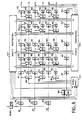
- the amplitudes A1, A2, A3 present at the output of each of the processing channels at each elementary time are first applied to validation P gates 101 to 103 controlled by the observability times of each sequence of pulses 11, 12 or 13 (see Figure 5). During the observability times, the amplitudes are transmitted without modification and, during the non-observability times, the P gates transmit a zero value. After passing through gates 101 to 103, the amplitudes are applied to circuits of the shift register type comprising L + 1 registers 111, 121 ... 151 for channel 1, 113, 123 ... 153 for channel 2, etc ..., where L is the number of moments of each modulation law, the progression in these registers taking place at the rate of elementary times.
- the amplitudes of the three channels are applied to a maximum detector circuit 104 which supplies on its output the rank i of the channel having the maximum amplitude at the instant considered. These amplitudes are also applied to a circuit 105 for calculating so-called simultaneous thresholds which provides, in response to the rank and the value of the maximum amplitude of the thresholds S Ij (O) corresponding to the coefficients at time 0 of one of the three possible configurations ( Figure 5) depending on the channel with a maximum. These thresholds are compared to the amplitudes A 1 in the respective comparators S 108 to 110 to provide a detection bit D equal to 1 if the threshold is equal to or less than the corresponding amplitude and to 0 if the threshold is greater.
- This bit is then transmitted to the next stage via a register R '112, 114, 116. All the other stages are then identical and each include a comparison circuit S' (for example 118 to 120 for l 'stage 1) followed by a register R' (for example 122, 124, 126 for stage 1).
- a comparison circuit S' for example 118 to 120 for l 'stage 1
- a register R' for example 122, 124, 126 for stage 1).
- a comparison circuit comprises, as shown in FIG. 9, two comparators Ca, Cp, receiving the amplitude A of the corresponding channel delayed by one to L elementary time depending on the stage considered and a respective threshold called anterior Sa or posterior S d , and an "AND" gate AG receiving the outputs of the comparators Ca and Cp and the detection bit D of the previous stage and supplying the new detection bit D '.
- Bit D ' is worth 1 if bit D is worth 1 and if the amplitude A is greater than the two thresholds Sa and Sp. Otherwise, it takes the value 0.
- the prior thresholds, for delays R from -1 to -L, are provided by an anterior threshold generator 107 while the posterior thresholds, for delays R from +1 to + L, are provided by a posterior threshold generator 106 .
- the previous thresholds are developed from the amplitudes at the input of the device and from the rank of the channel containing the maximum amplitude.
- the posterior thresholds are developed from the amplitudes appearing at the output of the device as well as from the rank of the channel containing at output the maximum amplitude. This rank is obtained by providing a parallel progression path for rank i supplied by circuit 104 through L + 1 registers R "117, 127 ... 157.
- Generators 106 and 107 are of strictly identical structure.
- circuit 105 selection circuit, read-only memory and multipliers
- the operation of the device of FIG. 8 thus appears clearly.
- the amplitudes appearing at the input of the device are used to calculate the previous thresholds which are compared to the corresponding previous amplitudes which are present in the various stages of the device, which makes it possible to cancel the secon peak amplitude detection bits detected, when the maximum amplitude at the input becomes higher.
- the amplitudes appearing at the output of the device are used to calculate the posterior thresholds which are compared with the corresponding amplitudes arrived later and which are present in the various stages of the device which makes it possible to cancel the bits for detecting peak amplitudes secondary detected, when the maximum amplitude at the output is significantly higher.
Applications Claiming Priority (2)
| Application Number | Priority Date | Filing Date | Title |
|---|---|---|---|
| FR8916789A FR2656108B1 (fr) | 1989-12-19 | 1989-12-19 | Procede et systeme radar coherent a impulsions pour la detection d'unhe cible presentant des eclairs de tres courte duree. |
| FR8916789 | 1989-12-19 |
Publications (1)
| Publication Number | Publication Date |
|---|---|
| EP0434503A1 true EP0434503A1 (de) | 1991-06-26 |
Family
ID=9388675
Family Applications (1)
| Application Number | Title | Priority Date | Filing Date |
|---|---|---|---|
| EP90403543A Withdrawn EP0434503A1 (de) | 1989-12-19 | 1990-12-12 | Kohärentes Impulsradarsystem und -verfahren zum Detektieren eines Ziels mit kurzzeitigen starken Reflexionen |
Country Status (3)
| Country | Link |
|---|---|
| US (1) | US5124710A (de) |
| EP (1) | EP0434503A1 (de) |
| FR (1) | FR2656108B1 (de) |
Cited By (3)
| Publication number | Priority date | Publication date | Assignee | Title |
|---|---|---|---|---|
| FR2722005A1 (fr) * | 1994-06-30 | 1996-01-05 | Loral Corp | Appareil et procede pour attenuer les ambiguites dans les radars doppler a impulsions |
| EP0740165A1 (de) * | 1995-04-25 | 1996-10-30 | Thomson-Csf | Signalbearbeitungsverfahren und Vorrichtung zum Entfernen von Mehrdeutigkeiten in einem Doppler-Radar |
| EP2821809A1 (de) * | 2013-07-05 | 2015-01-07 | Thales | Erfassungsverfahren mindestens eines Ziels mithilfe eines Dopplerradars mit unzweideutiger Messung der radialen Geschwindigkeit, und Doppler-Impuls-Radar-Gerät zur Umsetzung dieses Verfahrens |
Families Citing this family (11)
| Publication number | Priority date | Publication date | Assignee | Title |
|---|---|---|---|---|
| NL9101720A (nl) * | 1991-10-16 | 1993-05-17 | Hollandse Signaalapparaten Bv | Inrichting voor het waarnemen en determineren van helicopters. |
| NL1012373C2 (nl) | 1999-06-17 | 2000-12-19 | Hollandse Signaalapparaten Bv | Radarapparaat. |
| NL1020287C2 (nl) * | 2002-04-02 | 2003-10-03 | Thales Nederland Bv | Werkwijze voor meerdoelendetectie, met name voor toepassing in rondzoekradars met meerbundelvorming in elevatie. |
| US7259714B1 (en) * | 2005-05-04 | 2007-08-21 | Cataldo Thomas J | Unique space time adaptive system (USS) |
| US7522089B2 (en) * | 2006-06-12 | 2009-04-21 | Raytheon Company | Airborne look-down doppler radar tracking of hovering helicopters using rotor features |
| US10514454B1 (en) * | 2014-10-24 | 2019-12-24 | The United States of America, as represented by the Administrator of the Federal Aviation Administration | Techniques for mitigating the effects of complex structures on radar systems |
| JP6376985B2 (ja) * | 2015-02-13 | 2018-08-22 | 三菱電機株式会社 | 目標検出装置 |
| GB201510945D0 (en) * | 2015-06-22 | 2015-08-05 | Imp Innovations Ltd | Echo measurement |
| US9952319B2 (en) | 2015-12-08 | 2018-04-24 | Delphi Technologies, Inc. | Residue cancellation for automated vehicle MIMO radar |
| CN113631945A (zh) * | 2019-03-20 | 2021-11-09 | 京瓷株式会社 | 电子设备、电子设备的控制方法以及电子设备的控制程序 |
| US20240027577A1 (en) * | 2022-07-20 | 2024-01-25 | Applied Concepts, Inc. | Adaptive fan noise suppression for traffic radar systems |
Citations (5)
| Publication number | Priority date | Publication date | Assignee | Title |
|---|---|---|---|---|
| US3526894A (en) * | 1961-05-18 | 1970-09-01 | Thomson Houston Comp Francaise | Random modulation radar |
| US4275396A (en) * | 1979-10-12 | 1981-06-23 | Jacomini Omar J | Helicopter rotating blade detection system |
| US4513288A (en) * | 1982-03-29 | 1985-04-23 | The United States Of America As Represented By The Secretary Of The Army | Group-complementary code sets for implementing pulse-compression processing with optimum aperiodic autocorrelation and optimum cross-correlation properties |
| EP0187397A1 (de) * | 1984-12-11 | 1986-07-16 | Hollandse Signaalapparaten B.V. | Impulsradargerät |
| EP0336273A2 (de) * | 1988-04-02 | 1989-10-11 | Daimler-Benz Aerospace Aktiengesellschaft | Pulsdopplerradar |
Family Cites Families (8)
| Publication number | Priority date | Publication date | Assignee | Title |
|---|---|---|---|---|
| US3733603A (en) * | 1968-07-31 | 1973-05-15 | Us Army | Radar target identification system |
| IT1074498B (it) * | 1976-09-16 | 1985-04-20 | Selenia Ind Elettroniche | Perfezionamento nei sistemi di riduzione dell errore di elevazione per radar di inseguimento di bersagli a bassa quota |
| FR2463938B1 (fr) * | 1979-08-23 | 1985-07-26 | Labo Cent Telecommunicat | Radar doppler pour detecter et localiser les helicopteres |
| US4389647A (en) * | 1980-12-22 | 1983-06-21 | The United States Of America As Represented By The Secretary Of The Army | Doppler discrimination of aircraft targets |
| US4499467A (en) * | 1982-04-14 | 1985-02-12 | The United States Of America As Represented By The Secretary Of The Army | Doppler radar sets with target direction sensing capability |
| US4635058A (en) * | 1983-12-14 | 1987-01-06 | Rca Corporation | Vehicle identification system using radar and acoustic information |
| US4816833A (en) * | 1987-06-16 | 1989-03-28 | Westinghouse Electric Corp. | Pulse doppler surveillance post signal processing and scan to scan correlation |
| US4920347A (en) * | 1988-05-07 | 1990-04-24 | Mitsubishi Denki Kabushiki Kaisha | Pulse doppler radar system |
-
1989
- 1989-12-19 FR FR8916789A patent/FR2656108B1/fr not_active Expired - Fee Related
-
1990
- 1990-12-12 EP EP90403543A patent/EP0434503A1/de not_active Withdrawn
- 1990-12-17 US US07/628,165 patent/US5124710A/en not_active Expired - Fee Related
Patent Citations (5)
| Publication number | Priority date | Publication date | Assignee | Title |
|---|---|---|---|---|
| US3526894A (en) * | 1961-05-18 | 1970-09-01 | Thomson Houston Comp Francaise | Random modulation radar |
| US4275396A (en) * | 1979-10-12 | 1981-06-23 | Jacomini Omar J | Helicopter rotating blade detection system |
| US4513288A (en) * | 1982-03-29 | 1985-04-23 | The United States Of America As Represented By The Secretary Of The Army | Group-complementary code sets for implementing pulse-compression processing with optimum aperiodic autocorrelation and optimum cross-correlation properties |
| EP0187397A1 (de) * | 1984-12-11 | 1986-07-16 | Hollandse Signaalapparaten B.V. | Impulsradargerät |
| EP0336273A2 (de) * | 1988-04-02 | 1989-10-11 | Daimler-Benz Aerospace Aktiengesellschaft | Pulsdopplerradar |
Non-Patent Citations (1)
| Title |
|---|
| PROCEEDING OF THE 1988 IEEE NATIONAL RADAR CONFERENCE, Ann Arbor, Michigan, 20-21 avril 1988, pages 194-199, IEEE, New York, US; F.F. KRETSCHMER, Jr. et al.: "New radar pulse compression waveforms" * |
Cited By (7)
| Publication number | Priority date | Publication date | Assignee | Title |
|---|---|---|---|---|
| FR2722005A1 (fr) * | 1994-06-30 | 1996-01-05 | Loral Corp | Appareil et procede pour attenuer les ambiguites dans les radars doppler a impulsions |
| WO1996000909A1 (en) * | 1994-06-30 | 1996-01-11 | Loral Corporation | Apparatus and method for mitigating range-doppler ambiguities in pulse-doppler radars |
| AU699274B2 (en) * | 1994-06-30 | 1998-11-26 | Lockheed Martin Tactical Systems Inc. | Apparatus and method for mitigating range-doppler ambiguities in pulse -doppler radars |
| EP0740165A1 (de) * | 1995-04-25 | 1996-10-30 | Thomson-Csf | Signalbearbeitungsverfahren und Vorrichtung zum Entfernen von Mehrdeutigkeiten in einem Doppler-Radar |
| FR2733600A1 (fr) * | 1995-04-25 | 1996-10-31 | Thomson Csf | Procede et dispositif de traitement de signal pour lever l'ambiguite vitesse d'un radar doppler |
| EP2821809A1 (de) * | 2013-07-05 | 2015-01-07 | Thales | Erfassungsverfahren mindestens eines Ziels mithilfe eines Dopplerradars mit unzweideutiger Messung der radialen Geschwindigkeit, und Doppler-Impuls-Radar-Gerät zur Umsetzung dieses Verfahrens |
| FR3008191A1 (fr) * | 2013-07-05 | 2015-01-09 | Thales Sa | Procede de detection d'au moins une cible par radar doppler a impulsions avec mesure non ambigue de la vitesse radiale et radar doppler a impulsions pour la mise en oeuvre d'un tel procede |
Also Published As
| Publication number | Publication date |
|---|---|
| US5124710A (en) | 1992-06-23 |
| FR2656108A1 (fr) | 1991-06-21 |
| FR2656108B1 (fr) | 1993-02-05 |
Similar Documents
| Publication | Publication Date | Title |
|---|---|---|
| EP0818691B1 (de) | Verfahren und Vorrichtung zur Zielerfassung für Doppler Radargeräte mit Hilfe von breitbandigen eindeutigen Pulsen | |
| EP0120775B1 (de) | Entfernungs- und Dopplermessung mittels einer Laseranordnung mit Pulszeitraffung | |
| EP0434503A1 (de) | Kohärentes Impulsradarsystem und -verfahren zum Detektieren eines Ziels mit kurzzeitigen starken Reflexionen | |
| EP0681190B1 (de) | System und Verfahren zur diskreten Radarerkennung | |
| FR2718249A1 (fr) | Procédé et dispositif radar de mesure de distance. | |
| FR2540314A1 (fr) | Procede d'initialisation des coefficients de filtres dans un dispositif d'annulation d'echos proche et lointain et dispositif de mise en oeuvre de ce procede | |
| FR2731853A1 (fr) | Procede et dispositif de demodulation par echantillonnage, notamment pour systeme d'alarme de vehicule automobile | |
| FR2737307A1 (fr) | Systeme de mesure de distance | |
| EP1706757B1 (de) | Verfahren und empfängervorrichtung zur drahtlosen datenkommunikation mit ultrabreitbandigen zeitcodierten signalen | |
| EP0493189B1 (de) | Digitalkodierte Impulssignalverarbeitung | |
| EP3198299B1 (de) | Radardetektionsverfahren und radar zur implementierung des besagten verfahrens | |
| EP0546623A1 (de) | Ultraschallechograph zur Messung hoher Geschwindigkeiten von Blutströmungen | |
| EP0849889B1 (de) | Verfahren zum Mehrwegesignalempfang | |
| FR2640761A1 (de) | ||
| EP0098183B1 (de) | Annäherungsradar | |
| FR2894097A1 (fr) | Modem et procede pour transmettre des donnees dans un milieu notamment tel que l'air et l'eau | |
| FR2632421A1 (fr) | Emetteur et recepteur de message d'identification | |
| EP1058402A1 (de) | Verfahren zur Verarbeitung einer Kanalimpulsantwort mit adaptiver Schwelle und entsprechender Empfänger | |
| EP0010481A1 (de) | Verfahren und Vorrichtung zum Anzeigen bewegender Ziele, insbesondere bei einem Radargerät mit variabler Wiederholungsfrequenz | |
| EP1075122A1 (de) | Messung der Stossantwort für einen vom Schlupffaktor abhängigen Pseudo-Zufallscode | |
| EP0064900A1 (de) | Elektromagnetisches System mit Korrelation-Detektion und Annäherungszünder mit besagtem System | |
| FR2888336A1 (fr) | Procede et dispositif d'elimination de faux echos dus au pic parasite de la fonction d'intercorrelation dans un radar a onde continue codee en phase | |
| FR2639102A1 (fr) | Dispositif de guidage d'un missile | |
| EP1252722B1 (de) | Cdma-funkübertragungsverfahren mit zugriffskodes und empfänger dafür | |
| FR3125888A1 (fr) | Procede d'optimisation de la determination de la distance d'une cible par rapport a un radar a codage de phase en mode pulse |
Legal Events
| Date | Code | Title | Description |
|---|---|---|---|
| PUAI | Public reference made under article 153(3) epc to a published international application that has entered the european phase |
Free format text: ORIGINAL CODE: 0009012 |
|
| AK | Designated contracting states |
Kind code of ref document: A1 Designated state(s): DE GB |
|
| 17P | Request for examination filed |
Effective date: 19911220 |
|
| STAA | Information on the status of an ep patent application or granted ep patent |
Free format text: STATUS: THE APPLICATION IS DEEMED TO BE WITHDRAWN |
|
| 18D | Application deemed to be withdrawn |
Effective date: 19930701 |