EP0434497A1 - Faserwickelverfahren zur Herstellung eines ringförmigen Hohlkörpers mit inneren Versteifungen - Google Patents
Faserwickelverfahren zur Herstellung eines ringförmigen Hohlkörpers mit inneren Versteifungen Download PDFInfo
- Publication number
- EP0434497A1 EP0434497A1 EP90403506A EP90403506A EP0434497A1 EP 0434497 A1 EP0434497 A1 EP 0434497A1 EP 90403506 A EP90403506 A EP 90403506A EP 90403506 A EP90403506 A EP 90403506A EP 0434497 A1 EP0434497 A1 EP 0434497A1
- Authority
- EP
- European Patent Office
- Prior art keywords
- mandrel
- box
- filament winding
- winding
- internal wall
- Prior art date
- Legal status (The legal status is an assumption and is not a legal conclusion. Google has not performed a legal analysis and makes no representation as to the accuracy of the status listed.)
- Granted
Links
- 238000009730 filament winding Methods 0.000 title claims abstract description 22
- 238000000034 method Methods 0.000 title claims abstract description 14
- 238000004519 manufacturing process Methods 0.000 claims abstract description 8
- 238000004804 winding Methods 0.000 claims description 12
- 238000004873 anchoring Methods 0.000 claims description 8
- 238000006116 polymerization reaction Methods 0.000 claims description 7
- 239000004576 sand Substances 0.000 claims description 7
- 239000011324 bead Substances 0.000 claims description 6
- 238000005520 cutting process Methods 0.000 claims description 6
- 238000003754 machining Methods 0.000 claims description 5
- XLYOFNOQVPJJNP-UHFFFAOYSA-N water Substances O XLYOFNOQVPJJNP-UHFFFAOYSA-N 0.000 claims description 4
- 239000003351 stiffener Substances 0.000 claims description 3
- 239000000853 adhesive Substances 0.000 claims description 2
- 230000001070 adhesive effect Effects 0.000 claims description 2
- 230000003014 reinforcing effect Effects 0.000 claims description 2
- KWGRBVOPPLSCSI-WPRPVWTQSA-N (-)-ephedrine Chemical compound CN[C@@H](C)[C@H](O)C1=CC=CC=C1 KWGRBVOPPLSCSI-WPRPVWTQSA-N 0.000 description 7
- 239000000835 fiber Substances 0.000 description 4
- 239000000463 material Substances 0.000 description 3
- 239000003822 epoxy resin Substances 0.000 description 2
- 239000011796 hollow space material Substances 0.000 description 2
- 229920000647 polyepoxide Polymers 0.000 description 2
- OKTJSMMVPCPJKN-UHFFFAOYSA-N Carbon Chemical compound [C] OKTJSMMVPCPJKN-UHFFFAOYSA-N 0.000 description 1
- 238000000429 assembly Methods 0.000 description 1
- 239000011230 binding agent Substances 0.000 description 1
- 230000015572 biosynthetic process Effects 0.000 description 1
- 229910052799 carbon Inorganic materials 0.000 description 1
- 239000002131 composite material Substances 0.000 description 1
- 238000005260 corrosion Methods 0.000 description 1
- 230000007797 corrosion Effects 0.000 description 1
- 238000000605 extraction Methods 0.000 description 1
- 239000002184 metal Substances 0.000 description 1
- 230000002787 reinforcement Effects 0.000 description 1
- 229920005989 resin Polymers 0.000 description 1
- 239000011347 resin Substances 0.000 description 1
Images


Classifications
-
- B—PERFORMING OPERATIONS; TRANSPORTING
- B29—WORKING OF PLASTICS; WORKING OF SUBSTANCES IN A PLASTIC STATE IN GENERAL
- B29C—SHAPING OR JOINING OF PLASTICS; SHAPING OF MATERIAL IN A PLASTIC STATE, NOT OTHERWISE PROVIDED FOR; AFTER-TREATMENT OF THE SHAPED PRODUCTS, e.g. REPAIRING
- B29C53/00—Shaping by bending, folding, twisting, straightening or flattening; Apparatus therefor
- B29C53/56—Winding and joining, e.g. winding spirally
- B29C53/58—Winding and joining, e.g. winding spirally helically
- B29C53/583—Winding and joining, e.g. winding spirally helically for making tubular articles with particular features
- B29C53/588—Winding and joining, e.g. winding spirally helically for making tubular articles with particular features having a non-linear axis, e.g. elbows, toroids
Definitions
- the invention relates to a load-bearing structure and relates more precisely to a method of making by filament winding a closed annular closed-end box section hollow body incorporating internal stiffening elements, allowing it to work under complex mechanical stresses and having a minimum mass for space and stiffness imposed.
- This type of part is commonly in the form of a metallic lattice or box structure, composed of an assembly of elements linked together by mechanically welded, or riveted, or bolted, etc. connections, which generally leads to reinforcements of complex design.
- the disadvantage of this manufacturing method lies in its high cost resulting from a material consumption and significant time, in particular for the machining of the elements, their assembly and their assembly, also taking into account the difficulties of automation.
- the mass of the structure can thus be reduced by 30%, and the cost of production can be reduced by the fact that the number of parts to be assembled is reduced, the geometry of the components is simplified. parts in question, that the machining is considerably reduced and the connections are simplified. In addition, the material and the tools used are minimized.
- This version obtained by filament winding also has the advantage of considerably limiting corrosion problems.
- the primary mandrel is supported by a circular rim carried by a hub by means of radial brackets, and constituted by agglomerated sand maintained by a plurality of anchoring tubes.
- the internal wall of the annular box is consisting of a circumferential winding and a satellite winding with inclined layers.
- each stiffening element is produced on the one hand by filament winding of radial webs and on the other hand by filament winding of inserts followed by the engagement of said inserts at each end of a radial web .
- a positioning tube pierced with small holes is fixed on the anchoring tubes which extends in the intermediate zones between the stiffening elements, and which is intended to hold the intermediate mandrel, the winding of the walls lateral and external of the box above the intermediate mandrel being followed by cutting, after polymerization of the beads at the desired cutting level.
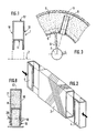
- FIG. 1 shows a part of a closed annular casing 1, of axis 2, made of composite material, of the high performance continuous fiber type coated with epoxy resin.
- the box 1 is hollow, of rectangular radial section. It is limited by side walls 10, an internal wall 11 and an internal wall 12. It is this box that is to be produced by incorporating into the hollow space stiffening elements, consisting of radial sails of shape rectangular.
- the fiber used is advantageously high-modulus carbon associated with an epoxy resin, a torque which makes it possible to best achieve the objectives of mass and stiffness.
- the filament winding process implemented on a numerically controlled machine is used, guaranteeing the definition parameters (orientation of the fibers and thicknesses) and thereby their reproducibility.
- FIG. 2 illustrates an embodiment of such a stiffening element. It consists first of all by making filament winding on a mandrel of suitable shape of the radial webs 3, of rectangular section, followed by the polymerization, the machining and the extraction of the mandrel.
- FIG. 3 illustrates the embodiment by filament winding of the internal wall of the annular box.
- the primary mandrel used for this purpose is supported by a circular metal rim 5 mounted on a series of radial brackets 6 carried by a central hub 7 serving for the support and for the rotary drive on the rotating machine.
- An anchoring tube 8 screwed onto the convex part of the rim 5 is used in particular to hold the agglomerated sand which constitutes this primary mandrel 9. It is formed by filament winding on the mandrel followed by polymerization, the internal wall 11 of the box 1.
- FIG. 4 shows, by way of example of an embodiment, a type of winding called "cycloprofile" of the internal wall 11 of the box consisting of a circumferential winding 11a and a satellite winding 11b with inclined layers, which causes the formation of beads 18 at the level of the central circle.
- cycloprofile a type of winding called "cycloprofile" of the internal wall 11 of the box consisting of a circumferential winding 11a and a satellite winding 11b with inclined layers, which causes the formation of beads 18 at the level of the central circle.
- the anchoring tube 8 then receives a positioning tube 19 pierced with small orifices 16, which extends in the intermediate zones between the stiffening elements and serves to maintain an intermediate mandrel 17, for example made of sand agglomerated by a soluble binder with water ( Figures 6 and 7).
- the side walls 10 and the external walls 12 of the box can then be produced by filament winding, around this intermediate mandrel 17.
- the winding is followed by polymerization, then, as illustrated in FIG. 8, by a cutout. small beads 18 due to the winding of the cycloprofiles, at the desired cutting level 20.
- the sand mandrel parts which constitute the intermediate mandrel are eliminated. It then remains to disengage the positioning tubes 19 from the intermediate mandrel, by the anchoring tube 8 in the direction of the arrow F, then the anchoring tubes themselves.
- Wall internal of the box will therefore have holes that will be easy to close, for example by glued plugs.
Landscapes
- Physics & Mathematics (AREA)
- Nonlinear Science (AREA)
- Engineering & Computer Science (AREA)
- Mechanical Engineering (AREA)
- Moulding By Coating Moulds (AREA)
Applications Claiming Priority (2)
| Application Number | Priority Date | Filing Date | Title |
|---|---|---|---|
| FR8916777 | 1989-12-19 | ||
| FR8916777A FR2655906B1 (fr) | 1989-12-19 | 1989-12-19 | Procede de realisation par enroulement filamentaire d'un caisson annulaire avec raidisseurs internes. |
Publications (2)
| Publication Number | Publication Date |
|---|---|
| EP0434497A1 true EP0434497A1 (de) | 1991-06-26 |
| EP0434497B1 EP0434497B1 (de) | 1994-08-24 |
Family
ID=9388668
Family Applications (1)
| Application Number | Title | Priority Date | Filing Date |
|---|---|---|---|
| EP90403506A Expired - Lifetime EP0434497B1 (de) | 1989-12-19 | 1990-12-10 | Faserwickelverfahren zur Herstellung eines ringförmigen Hohlkörpers mit inneren Versteifungen |
Country Status (4)
| Country | Link |
|---|---|
| US (1) | US5200012A (de) |
| EP (1) | EP0434497B1 (de) |
| DE (1) | DE69011827T2 (de) |
| FR (1) | FR2655906B1 (de) |
Families Citing this family (6)
| Publication number | Priority date | Publication date | Assignee | Title |
|---|---|---|---|---|
| US5362344A (en) * | 1993-02-03 | 1994-11-08 | Avco Corporation | Ducted support housing assembly |
| FR2707552B1 (fr) * | 1993-06-30 | 1995-10-13 | Aerospatiale | Procédé de fabrication d'une pièce en matériau composite composée, d'un corps central et d'ailerons et corps de missile ainsi obtenu. |
| US6655633B1 (en) * | 2000-01-21 | 2003-12-02 | W. Cullen Chapman, Jr. | Tubular members integrated to form a structure |
| US20050100414A1 (en) * | 2003-11-07 | 2005-05-12 | Conocophillips Company | Composite riser with integrity monitoring apparatus and method |
| GB0710832D0 (en) * | 2007-06-06 | 2007-07-18 | Airbus Uk Ltd | Fibre placement tool |
| FR2949091B1 (fr) * | 2009-08-17 | 2015-06-26 | Snecma | Procede de realisation d'un disque aubage monobloc creux |
Citations (2)
| Publication number | Priority date | Publication date | Assignee | Title |
|---|---|---|---|---|
| DE3316539C1 (de) * | 1983-05-06 | 1984-04-05 | Messerschmitt-Bölkow-Blohm GmbH, 8000 München | Torusfoermiger Druckbehaelter aus Verbundmaterial |
| EP0165163A1 (de) * | 1984-05-30 | 1985-12-18 | AEROSPATIALE Société Nationale Industrielle | Komplex zusammengefügtes Konstruktionselement |
Family Cites Families (7)
| Publication number | Priority date | Publication date | Assignee | Title |
|---|---|---|---|---|
| US3020956A (en) * | 1959-01-28 | 1962-02-13 | De Long Corp | Apparatus and method for connecting an access caission to a submerged well casing |
| US3607504A (en) * | 1969-01-30 | 1971-09-21 | Rohr Corp | Method of fabricating a box beam |
| JPS5817072A (ja) * | 1981-07-16 | 1983-02-01 | Iwatsu Electric Co Ltd | トロイダル捲線機 |
| DE3316530A1 (de) * | 1983-05-06 | 1984-11-08 | Dr.-Ing. Farkas Ingenieurbüro, 4700 Hamm | Seilbahnanlage, insbesondere fuer den transport im untertaegigen berg- und tunnelbau vorgesehene seilbahn |
| US4634314A (en) * | 1984-06-26 | 1987-01-06 | Vetco Offshore Inc. | Composite marine riser system |
| JPS62257835A (ja) * | 1986-05-06 | 1987-11-10 | Mitsubishi Electric Corp | サンドイツチ構造体およびその製造方法 |
| US4854778A (en) * | 1987-09-04 | 1989-08-08 | Cameron Iron Works Usa, Inc. | Caisson tower platform and method of setting same |
-
1989
- 1989-12-19 FR FR8916777A patent/FR2655906B1/fr not_active Expired - Fee Related
-
1990
- 1990-12-10 DE DE69011827T patent/DE69011827T2/de not_active Expired - Fee Related
- 1990-12-10 EP EP90403506A patent/EP0434497B1/de not_active Expired - Lifetime
- 1990-12-11 US US07/625,402 patent/US5200012A/en not_active Expired - Fee Related
Patent Citations (2)
| Publication number | Priority date | Publication date | Assignee | Title |
|---|---|---|---|---|
| DE3316539C1 (de) * | 1983-05-06 | 1984-04-05 | Messerschmitt-Bölkow-Blohm GmbH, 8000 München | Torusfoermiger Druckbehaelter aus Verbundmaterial |
| EP0165163A1 (de) * | 1984-05-30 | 1985-12-18 | AEROSPATIALE Société Nationale Industrielle | Komplex zusammengefügtes Konstruktionselement |
Also Published As
| Publication number | Publication date |
|---|---|
| DE69011827T2 (de) | 1995-03-09 |
| DE69011827D1 (de) | 1994-09-29 |
| EP0434497B1 (de) | 1994-08-24 |
| FR2655906A1 (fr) | 1991-06-21 |
| US5200012A (en) | 1993-04-06 |
| FR2655906B1 (fr) | 1992-04-03 |
Similar Documents
| Publication | Publication Date | Title |
|---|---|---|
| EP1892120B1 (de) | Speiche für ein Speichenrad, Herstellungsverfahren und Rad mit mindestens einer solchen Speiche | |
| EP2652185B1 (de) | Fasergebilde für ein verbundmaterialteil mit einem oder mehreren bogenförmigen teilen | |
| EP3134246B1 (de) | Vefahren zum herstelen eines zahnrades mittels doppeltem spritzgiessen | |
| EP0335781B1 (de) | Eine Verbundstruktur aufweisender Körper für Antriebsgelenke und Verfahren zu dessen Herstellung | |
| EP3209484B1 (de) | Anordnung von zwei teilen durch ein element zur mechanischen verankerung, von denen eines aus verbundwerkstoff gefertigt ist | |
| FR2925896A1 (fr) | Procede de fabrication d'une piece metallique renforcee de fibres ceramiques | |
| EP2946033B1 (de) | Faserstruktur für eine aus einem verbundwerkstoff hergestellte achsensymmetrische komponente mit sich progressiv änderndem durchmesser und bauteil damit | |
| FR3017819A1 (fr) | Renfort fibreux pour la realisation d'une piece mecanique allongee en materiau composite | |
| EP2951002A1 (de) | Verbessertes verfahren zur herstellung einer getriebewelle, vorzugsweise für einen zubehörkasten einer flugzeugturbomaschine | |
| EP0434497B1 (de) | Faserwickelverfahren zur Herstellung eines ringförmigen Hohlkörpers mit inneren Versteifungen | |
| EP0176386A1 (de) | Herstellungsverfahren eines Turbinen- oder Compressorrades aus Verbundwerkstoff, und dementsprechend erhaltenes Rad | |
| EP1215365A1 (de) | Verstellbare Statorschaufel und Produktionsmethode | |
| EP2008835A1 (de) | Rad mit ausbaubarer Speiche aus Verbundmaterial | |
| EP0340088A1 (de) | Verbundwerkstoff-Hülse mit integrierten Flügeln für einen Raketentreibsatz und ihre Herstellung | |
| WO2020260804A1 (fr) | Piece de revolution en materiau composite ayant une resistance au delaminage amelioree | |
| EP3152027B1 (de) | Verfahren zur herstellung eines zahnrades mit verstärkungsreifen | |
| WO2018215717A1 (fr) | Structure fibreuse tubulaire a lobes | |
| EP1798429B1 (de) | Rohrförmige Pleuelstange aus einem Verbundmaterial und ein entsprechendes Herstellungsverfahren | |
| FR2915710A1 (fr) | Rayon en metal et matiere composite pour une roue a rayons. | |
| FR2549160A1 (fr) | Procede de fabrication d'un rotor pour une pompe a fluides rotative | |
| EP3636410B1 (de) | Herstellungsverfahren eines aufformteils, das ein strukturteil eines fahrzeugs bildet | |
| CA2764774C (fr) | Procede de fabrication d'une piece metallique incorporant un renfort annulaire fibreux | |
| EP3717767B1 (de) | Zusätzlicher booster mit optimierter architektur | |
| EP0900644B1 (de) | Verfahren zur Herstellung eines Verbundmaterials mit Kernfasern und damit hergestellte Faserstruktur | |
| WO2023105155A1 (fr) | Procede de fabrication d'une piece aubagee pour une turbomachine d'aeronef |
Legal Events
| Date | Code | Title | Description |
|---|---|---|---|
| PUAI | Public reference made under article 153(3) epc to a published international application that has entered the european phase |
Free format text: ORIGINAL CODE: 0009012 |
|
| AK | Designated contracting states |
Kind code of ref document: A1 Designated state(s): BE CH DE ES GB IT LI |
|
| 17P | Request for examination filed |
Effective date: 19911214 |
|
| 17Q | First examination report despatched |
Effective date: 19930426 |
|
| GRAA | (expected) grant |
Free format text: ORIGINAL CODE: 0009210 |
|
| ITF | It: translation for a ep patent filed | ||
| AK | Designated contracting states |
Kind code of ref document: B1 Designated state(s): BE CH DE ES GB IT LI |
|
| PG25 | Lapsed in a contracting state [announced via postgrant information from national office to epo] |
Ref country code: ES Free format text: THE PATENT HAS BEEN ANNULLED BY A DECISION OF A NATIONAL AUTHORITY Effective date: 19940824 |
|
| REF | Corresponds to: |
Ref document number: 69011827 Country of ref document: DE Date of ref document: 19940929 |
|
| PG25 | Lapsed in a contracting state [announced via postgrant information from national office to epo] |
Ref country code: LI Effective date: 19941231 Ref country code: CH Effective date: 19941231 Ref country code: BE Effective date: 19941231 |
|
| GBT | Gb: translation of ep patent filed (gb section 77(6)(a)/1977) |
Effective date: 19941129 |
|
| PLBE | No opposition filed within time limit |
Free format text: ORIGINAL CODE: 0009261 |
|
| STAA | Information on the status of an ep patent application or granted ep patent |
Free format text: STATUS: NO OPPOSITION FILED WITHIN TIME LIMIT |
|
| BERE | Be: lapsed |
Owner name: AEROSPATIALE SOC. NATIONALE INDUSTRIELLE Effective date: 19941231 |
|
| 26N | No opposition filed | ||
| REG | Reference to a national code |
Ref country code: CH Ref legal event code: PL |
|
| PGFP | Annual fee paid to national office [announced via postgrant information from national office to epo] |
Ref country code: DE Payment date: 20001202 Year of fee payment: 11 |
|
| PGFP | Annual fee paid to national office [announced via postgrant information from national office to epo] |
Ref country code: GB Payment date: 20001213 Year of fee payment: 11 |
|
| PG25 | Lapsed in a contracting state [announced via postgrant information from national office to epo] |
Ref country code: GB Free format text: LAPSE BECAUSE OF NON-PAYMENT OF DUE FEES Effective date: 20011210 |
|
| REG | Reference to a national code |
Ref country code: GB Ref legal event code: IF02 |
|
| PG25 | Lapsed in a contracting state [announced via postgrant information from national office to epo] |
Ref country code: DE Free format text: LAPSE BECAUSE OF NON-PAYMENT OF DUE FEES Effective date: 20020702 |
|
| GBPC | Gb: european patent ceased through non-payment of renewal fee |
Effective date: 20011210 |
|
| PG25 | Lapsed in a contracting state [announced via postgrant information from national office to epo] |
Ref country code: IT Free format text: LAPSE BECAUSE OF NON-PAYMENT OF DUE FEES;WARNING: LAPSES OF ITALIAN PATENTS WITH EFFECTIVE DATE BEFORE 2007 MAY HAVE OCCURRED AT ANY TIME BEFORE 2007. THE CORRECT EFFECTIVE DATE MAY BE DIFFERENT FROM THE ONE RECORDED. Effective date: 20051210 |