EP0434293A2 - Verfahren und Einrichtung zum Detektieren von FM oder PM modulierter Signale - Google Patents
Verfahren und Einrichtung zum Detektieren von FM oder PM modulierter Signale Download PDFInfo
- Publication number
- EP0434293A2 EP0434293A2 EP90313521A EP90313521A EP0434293A2 EP 0434293 A2 EP0434293 A2 EP 0434293A2 EP 90313521 A EP90313521 A EP 90313521A EP 90313521 A EP90313521 A EP 90313521A EP 0434293 A2 EP0434293 A2 EP 0434293A2
- Authority
- EP
- European Patent Office
- Prior art keywords
- delay line
- frequency
- time interval
- delay
- measurement
- Prior art date
- Legal status (The legal status is an assumption and is not a legal conclusion. Google has not performed a legal analysis and makes no representation as to the accuracy of the status listed.)
- Granted
Links
- 238000000034 method Methods 0.000 title claims abstract description 20
- 238000001514 detection method Methods 0.000 title claims abstract description 7
- 238000005259 measurement Methods 0.000 claims abstract description 29
- 230000001902 propagating effect Effects 0.000 claims 2
- 238000004519 manufacturing process Methods 0.000 description 2
- 230000035945 sensitivity Effects 0.000 description 2
- 230000005540 biological transmission Effects 0.000 description 1
- 238000010276 construction Methods 0.000 description 1
- 238000010586 diagram Methods 0.000 description 1
- 238000005457 optimization Methods 0.000 description 1
- 238000010079 rubber tapping Methods 0.000 description 1
- 238000001228 spectrum Methods 0.000 description 1
- 230000003068 static effect Effects 0.000 description 1
Images

Classifications
-
- H—ELECTRICITY
- H03—ELECTRONIC CIRCUITRY
- H03D—DEMODULATION OR TRANSFERENCE OF MODULATION FROM ONE CARRIER TO ANOTHER
- H03D3/00—Demodulation of angle-, frequency- or phase- modulated oscillations
- H03D3/02—Demodulation of angle-, frequency- or phase- modulated oscillations by detecting phase difference between two signals obtained from input signal
- H03D3/04—Demodulation of angle-, frequency- or phase- modulated oscillations by detecting phase difference between two signals obtained from input signal by counting or integrating cycles of oscillations
-
- G—PHYSICS
- G01—MEASURING; TESTING
- G01R—MEASURING ELECTRIC VARIABLES; MEASURING MAGNETIC VARIABLES
- G01R23/00—Arrangements for measuring frequencies; Arrangements for analysing frequency spectra
- G01R23/02—Arrangements for measuring frequency, e.g. pulse repetition rate; Arrangements for measuring period of current or voltage
- G01R23/10—Arrangements for measuring frequency, e.g. pulse repetition rate; Arrangements for measuring period of current or voltage by converting frequency into a train of pulses, which are then counted, i.e. converting the signal into a square wave
Definitions
- the object of the invention is a method based on direct time interval measurement for the detection of an FM or PM modulated signal and a device for that purpose.
- a phase or frequency modulated transmission is often detected with a phase lock comprising a phase discriminator, a loop filter and a controlled oscillator, which interlocks on the same frequency with the input signal.
- the controlling signal for the oscillator is used as the detected signal.
- the phase lock it is possible to realize the phase lock as an analog or a digital phase lock.
- the characteristics of an analog phase lock are influenced i.a. by the control range of the voltage controlled oscillator and linearity and by the output noise of the loop filter.
- a controlled oscillator in a digital phase lock is more easily designed to be linear than an analog oscillator, but a digital phase lock can be locked only to discrete frequencies, whereby the detected signal will include phase noise, the oscillator changing between the two closest frequencies.
- the digital phase locks operate further on relatively low frequencies.
- a phase lock is a non-linear, closed loop system, the behavior of which it is difficult to analyze. The optimization of the characteristics is limited by the feedback loop, which has to remain stable.
- Analog phase locks consume power continuously, and often they use coils, which are inconvenient components regarding the production engineering.
- Digital filters are often used in modems, whereby the detected signal must be converted into a digital signal with separate analog-to-digital converters.
- This invention presents a method, with which it is possible to detect an FM or PM modulated signal directly without the disadvantages of the analog or digital phase lock.
- the input signal frequency or phase is measured sufficiently often with respect to the bandwidth of the modulating signal, whereby samples of the modulating signal are obtained, taken directly at the measurement frequency.
- the method includes no feedback loop, whereby the measurement results can be processed more freely than when phase locks are used.
- the invention also relates to a device in which the described method is utilized.
- the method according to the invention is characterized by features presented in the characterizing clause of claim 1, and the device is characterized by features presented in claim 7.
- the signal is detected so that the instantaneous cycle time of the modulated input frequency is measured by direct time interval measurement using a time-to-digital converter. Cycle time deviations from the cycle time of the nominal frequency indicate phase changes, and the phase modulation can be evaluated from them. The inverse of the cycle time gives directly the instantaneous frequency. Because the method demands from the time measurement a higher resolution than normal frequency counters can achieve with reasonable clock frequencies, the measurement sensitivity is improved in accordance with the invention with a digital interpolator, which preferably is a delay line consisting of delay elements. The delay line can be realized in different ways as will be apparent in the subclaims.
- the detection according to the invention is based on the measurement of the modulated input signal instantaneous cycle time with a direct time interval measurement using a time-to-digital converter.
- the cycle time 3 of the signal 1 is measured with a time interval measuring instrument 2.
- the signal is demodulated in the block 4.
- the instantaneous frequency 5 is obtained as the inverse of the instantaneous cycle time, the phase modulation is detected as instantaneous cycle time changes.
- the detected signal 5 is directed for further processing in a filter and limiter block 6.
- the measuring method does not include any feedback loop, whereby the processing of the measurement results can be made more freely than when phase locks are used.
- the result obtained is also already digital.
- the method according to the invention demands a very high resolution from the time measurement.
- the measurement sensitivity is increased by using in addition to the counter a digital interpolator, of which in figure 2 there is shown the operating principle in time interval measurements with a delay line composed of delay elements: at the beginning of the time interval a pulse or its edge 8 is sent into the delay line 9, the edge setting the data inputs of the flip-flops 10 when it propagates through the delay line consisting of delay elements ⁇ T.
- the time interval is ended the state of the delay line is stored and the length of the time interval is coded from the position of the last set flip-flop. It is possible to achieve a single measurement resolution less than one nanosecond by using fast logic gates as delay elements.
- the construction of figure 2 may be used, or the delay elements may themselves be flip-flops, the delay of which is used as the delay unit.
- the time interval end mark can also have its own delay line, faster than the delay line for the start mark, or the start and end marks can propagate in the same delay line but with different speeds.
- the time measurement which is based on a delay line can be used either on its own or in combination with a frequency counter principle according to figure 3, whereby the time interval 12 is coarsely quantized by counting cycles of the known reference clock with the counter 13, and more accurately by quantizing the clock cycle fractions with two delay lines 14, 15.
- the delay of the delay lines can also be adjustable, whereby it is possible to adjust the total length and the resolution of the delay line to a desired value.
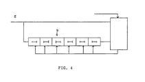
- the total delay of the delay line 9 can be calibrated to equal the reference clock cycle e.g. automatically with nine clock signals S according to figure 4.
- a small frequency deviation can thus be evaluated directly from the cycle time deviation without using any correction tables or calculation.
- the method is applied in such a way that measuring results of the time interval, which exceed a known modulation or which are otherwise unsuitable, can be discarded, limited or replaced with other values, and that said measurement results can be averaged, filtered or otherwise processed so that disturbances in the signal are minimized.
- the device according to the invention presents in production engineering terms an easy and little power consuming direct detection, which will not present restrictions on means for the removal of disturbances in the signal.
- the detected result is already in digital form, so that no separate analog-to-digital converter will be needed.
Landscapes
- Power Engineering (AREA)
- Physics & Mathematics (AREA)
- General Physics & Mathematics (AREA)
- Engineering & Computer Science (AREA)
- Measuring Frequencies, Analyzing Spectra (AREA)
- Stabilization Of Oscillater, Synchronisation, Frequency Synthesizers (AREA)
- Measurement Of Mechanical Vibrations Or Ultrasonic Waves (AREA)
- Digital Transmission Methods That Use Modulated Carrier Waves (AREA)
- Arrangements For Transmission Of Measured Signals (AREA)
- Burglar Alarm Systems (AREA)
- Measurement And Recording Of Electrical Phenomena And Electrical Characteristics Of The Living Body (AREA)
- Manipulation Of Pulses (AREA)
- Ultra Sonic Daignosis Equipment (AREA)
Applications Claiming Priority (2)
| Application Number | Priority Date | Filing Date | Title |
|---|---|---|---|
| FI896267 | 1989-12-22 | ||
| FI896267A FI88559C (fi) | 1989-12-22 | 1989-12-22 | Anordning foer detektering av en FM- eller PM-modulerad signal |
Publications (3)
| Publication Number | Publication Date |
|---|---|
| EP0434293A2 true EP0434293A2 (de) | 1991-06-26 |
| EP0434293A3 EP0434293A3 (en) | 1991-09-04 |
| EP0434293B1 EP0434293B1 (de) | 1996-03-27 |
Family
ID=8529590
Family Applications (1)
| Application Number | Title | Priority Date | Filing Date |
|---|---|---|---|
| EP90313521A Expired - Lifetime EP0434293B1 (de) | 1989-12-22 | 1990-12-12 | Verfahren und Einrichtung zum Detektieren von FM oder PM modulierter Signale |
Country Status (5)
| Country | Link |
|---|---|
| EP (1) | EP0434293B1 (de) |
| JP (1) | JP3153253B2 (de) |
| AT (1) | ATE136172T1 (de) |
| DE (1) | DE69026222T2 (de) |
| FI (1) | FI88559C (de) |
Cited By (2)
| Publication number | Priority date | Publication date | Assignee | Title |
|---|---|---|---|---|
| WO2007034992A3 (en) * | 2005-09-23 | 2007-07-12 | Matsushita Electric Industrial Co Ltd | An apparatus and method for multi-phase digital sampling |
| WO2010077426A1 (en) * | 2008-12-08 | 2010-07-08 | General Electric Company | Methods for determining the frequency or period of a signal |
Family Cites Families (2)
| Publication number | Priority date | Publication date | Assignee | Title |
|---|---|---|---|---|
| US4593266A (en) * | 1983-08-08 | 1986-06-03 | Rca Corporation | Analog-to-digital converter/demodulator for FM signals |
| GB2204201A (en) * | 1986-10-24 | 1988-11-02 | Vnii Radiovesh Priema Akustiki | Method and device for receiving frequency-modulated analog signals with digital processing |
-
1989
- 1989-12-22 FI FI896267A patent/FI88559C/fi not_active IP Right Cessation
-
1990
- 1990-12-12 AT AT90313521T patent/ATE136172T1/de active
- 1990-12-12 DE DE69026222T patent/DE69026222T2/de not_active Expired - Fee Related
- 1990-12-12 EP EP90313521A patent/EP0434293B1/de not_active Expired - Lifetime
- 1990-12-25 JP JP40582790A patent/JP3153253B2/ja not_active Expired - Fee Related
Cited By (7)
| Publication number | Priority date | Publication date | Assignee | Title |
|---|---|---|---|---|
| WO2007034992A3 (en) * | 2005-09-23 | 2007-07-12 | Matsushita Electric Industrial Co Ltd | An apparatus and method for multi-phase digital sampling |
| US7570721B2 (en) | 2005-09-23 | 2009-08-04 | Panasonic Corporation | Apparatus and method for multi-phase digital sampling |
| CN101268376B (zh) * | 2005-09-23 | 2011-06-22 | 松下电器产业株式会社 | 进行多相数字采样的装置和方法 |
| WO2010077426A1 (en) * | 2008-12-08 | 2010-07-08 | General Electric Company | Methods for determining the frequency or period of a signal |
| GB2478227A (en) * | 2008-12-08 | 2011-08-31 | Gen Electric | Methods for determining the frequency or period of a signal |
| US8422340B2 (en) | 2008-12-08 | 2013-04-16 | General Electric Company | Methods for determining the frequency or period of a signal |
| GB2478227B (en) * | 2008-12-08 | 2016-02-24 | Gen Electric | Methods for determining the frequency or period of a signal |
Also Published As
| Publication number | Publication date |
|---|---|
| FI896267A0 (fi) | 1989-12-22 |
| ATE136172T1 (de) | 1996-04-15 |
| FI88559B (fi) | 1993-02-15 |
| DE69026222D1 (de) | 1996-05-02 |
| FI896267L (fi) | 1991-06-23 |
| JP3153253B2 (ja) | 2001-04-03 |
| EP0434293B1 (de) | 1996-03-27 |
| DE69026222T2 (de) | 1996-08-14 |
| FI88559C (fi) | 1993-05-25 |
| EP0434293A3 (en) | 1991-09-04 |
| JPH04138703A (ja) | 1992-05-13 |
Similar Documents
| Publication | Publication Date | Title |
|---|---|---|
| US5367200A (en) | Method and apparatus for measuring the duty cycle of a digital signal | |
| US3968427A (en) | Group delay measurement apparatus and method | |
| US4975634A (en) | Jitter measurement device | |
| CA2011661A1 (en) | Jitter measurement device | |
| EP0106029A1 (de) | Methode und Vorrichtung zur Messung der Amplitude eines verrauschten periodischen Signals ohne Phasenreferenz | |
| US5028886A (en) | Swept frequency slope correction system for synthesized sweeper | |
| US4494067A (en) | Fast frequency measuring system | |
| US4414639A (en) | Sampling network analyzer with sampling synchronization by means of phase-locked loop | |
| EP0434293A2 (de) | Verfahren und Einrichtung zum Detektieren von FM oder PM modulierter Signale | |
| DE102004015771A1 (de) | Anordnung zur Drehmomentmessung von rotierenden Maschinenteilen | |
| US3938042A (en) | Measurement averaging counting apparatus employing a randomly phase modulated time base to improve counting resolution | |
| US4068171A (en) | Frequency comparator | |
| Djokic et al. | Two methods for improved measurements of reactive power and reactive energy insensitive to frequency variations | |
| US4035736A (en) | FM discriminator having low noise characteristics | |
| GB2267617A (en) | A digital sample and hold phase detector | |
| RU2138828C1 (ru) | Устройство для измерения девиации частоты | |
| SU1129540A1 (ru) | Устройство дл контрол частотных генераторов с линейной частотной модул цией | |
| SU617750A1 (ru) | Устройство дл изменени добротности пьезоэлектрических резонаторов | |
| RU2187824C1 (ru) | Модуляционный радиометр | |
| SU875294A2 (ru) | Устройство дл измерени скорости девиации частоты | |
| JPH10260208A (ja) | 位相ゆらぎ検出装置 | |
| RU2011292C1 (ru) | Устройство автоматической подстройки частоты | |
| SU1095090A1 (ru) | Устройство дл измерени скорости изменени и девиации частоты сигнала с линейной частотной модул цией | |
| JP2001165968A (ja) | 位相ゆらぎ検出装置 | |
| JPS61176864A (ja) | 交流信号の測定回路 |
Legal Events
| Date | Code | Title | Description |
|---|---|---|---|
| PUAI | Public reference made under article 153(3) epc to a published international application that has entered the european phase |
Free format text: ORIGINAL CODE: 0009012 |
|
| AK | Designated contracting states |
Kind code of ref document: A2 Designated state(s): AT BE CH DE DK ES FR GB GR IT LI LU NL SE |
|
| PUAL | Search report despatched |
Free format text: ORIGINAL CODE: 0009013 |
|
| AK | Designated contracting states |
Kind code of ref document: A3 Designated state(s): AT BE CH DE DK ES FR GB GR IT LI LU NL SE |
|
| 17P | Request for examination filed |
Effective date: 19920304 |
|
| 17Q | First examination report despatched |
Effective date: 19920629 |
|
| GRAA | (expected) grant |
Free format text: ORIGINAL CODE: 0009210 |
|
| AK | Designated contracting states |
Kind code of ref document: B1 Designated state(s): AT BE CH DE DK ES FR GB GR IT LI LU NL SE |
|
| PG25 | Lapsed in a contracting state [announced via postgrant information from national office to epo] |
Ref country code: IT Free format text: LAPSE BECAUSE OF FAILURE TO SUBMIT A TRANSLATION OF THE DESCRIPTION OR TO PAY THE FEE WITHIN THE PRE;WARNING: LAPSES OF ITALIAN PATENTS WITH EFFECTIVE DATE BEFORE 2007 MAY HAVE OCCURRED AT ANY TIME BEFORE 2007. THE CORRECT EFFECTIVE DATE MAY BE DIFFERENT FROM THE ONE RECORDED.SCRIBED TIME-LIMIT Effective date: 19960327 Ref country code: GR Free format text: LAPSE BECAUSE OF FAILURE TO SUBMIT A TRANSLATION OF THE DESCRIPTION OR TO PAY THE FEE WITHIN THE PRESCRIBED TIME-LIMIT Effective date: 19960327 Ref country code: CH Effective date: 19960327 Ref country code: DK Effective date: 19960327 Ref country code: AT Effective date: 19960327 Ref country code: LI Effective date: 19960327 Ref country code: BE Effective date: 19960327 Ref country code: ES Free format text: THE PATENT HAS BEEN ANNULLED BY A DECISION OF A NATIONAL AUTHORITY Effective date: 19960327 |
|
| REF | Corresponds to: |
Ref document number: 136172 Country of ref document: AT Date of ref document: 19960415 Kind code of ref document: T |
|
| REF | Corresponds to: |
Ref document number: 69026222 Country of ref document: DE Date of ref document: 19960502 |
|
| ET | Fr: translation filed | ||
| REG | Reference to a national code |
Ref country code: CH Ref legal event code: PL |
|
| PG25 | Lapsed in a contracting state [announced via postgrant information from national office to epo] |
Ref country code: LU Free format text: LAPSE BECAUSE OF NON-PAYMENT OF DUE FEES Effective date: 19961231 |
|
| PLBE | No opposition filed within time limit |
Free format text: ORIGINAL CODE: 0009261 |
|
| STAA | Information on the status of an ep patent application or granted ep patent |
Free format text: STATUS: NO OPPOSITION FILED WITHIN TIME LIMIT |
|
| 26N | No opposition filed | ||
| PGFP | Annual fee paid to national office [announced via postgrant information from national office to epo] |
Ref country code: SE Payment date: 20011206 Year of fee payment: 12 |
|
| PGFP | Annual fee paid to national office [announced via postgrant information from national office to epo] |
Ref country code: GB Payment date: 20011212 Year of fee payment: 12 Ref country code: FR Payment date: 20011212 Year of fee payment: 12 |
|
| PGFP | Annual fee paid to national office [announced via postgrant information from national office to epo] |
Ref country code: NL Payment date: 20011228 Year of fee payment: 12 |
|
| REG | Reference to a national code |
Ref country code: GB Ref legal event code: IF02 |
|
| PGFP | Annual fee paid to national office [announced via postgrant information from national office to epo] |
Ref country code: DE Payment date: 20020109 Year of fee payment: 12 |
|
| REG | Reference to a national code |
Ref country code: GB Ref legal event code: 732E |
|
| PG25 | Lapsed in a contracting state [announced via postgrant information from national office to epo] |
Ref country code: GB Free format text: LAPSE BECAUSE OF NON-PAYMENT OF DUE FEES Effective date: 20021212 |
|
| PG25 | Lapsed in a contracting state [announced via postgrant information from national office to epo] |
Ref country code: SE Free format text: LAPSE BECAUSE OF NON-PAYMENT OF DUE FEES Effective date: 20021213 |
|
| PG25 | Lapsed in a contracting state [announced via postgrant information from national office to epo] |
Ref country code: NL Free format text: LAPSE BECAUSE OF NON-PAYMENT OF DUE FEES Effective date: 20030701 Ref country code: DE Free format text: LAPSE BECAUSE OF NON-PAYMENT OF DUE FEES Effective date: 20030701 |
|
| EUG | Se: european patent has lapsed | ||
| GBPC | Gb: european patent ceased through non-payment of renewal fee | ||
| NLV4 | Nl: lapsed or anulled due to non-payment of the annual fee |
Effective date: 20030701 |
|
| PG25 | Lapsed in a contracting state [announced via postgrant information from national office to epo] |
Ref country code: FR Free format text: LAPSE BECAUSE OF NON-PAYMENT OF DUE FEES Effective date: 20030901 |
|
| REG | Reference to a national code |
Ref country code: FR Ref legal event code: ST |