EP0434191A2 - Elektrooptische Systeme zur Abstandsmessung - Google Patents
Elektrooptische Systeme zur Abstandsmessung Download PDFInfo
- Publication number
- EP0434191A2 EP0434191A2 EP90311283A EP90311283A EP0434191A2 EP 0434191 A2 EP0434191 A2 EP 0434191A2 EP 90311283 A EP90311283 A EP 90311283A EP 90311283 A EP90311283 A EP 90311283A EP 0434191 A2 EP0434191 A2 EP 0434191A2
- Authority
- EP
- European Patent Office
- Prior art keywords
- source
- detector
- delay
- light
- frequency
- Prior art date
- Legal status (The legal status is an assumption and is not a legal conclusion. Google has not performed a legal analysis and makes no representation as to the accuracy of the status listed.)
- Withdrawn
Links
Images


Classifications
-
- G—PHYSICS
- G01—MEASURING; TESTING
- G01S—RADIO DIRECTION-FINDING; RADIO NAVIGATION; DETERMINING DISTANCE OR VELOCITY BY USE OF RADIO WAVES; LOCATING OR PRESENCE-DETECTING BY USE OF THE REFLECTION OR RERADIATION OF RADIO WAVES; ANALOGOUS ARRANGEMENTS USING OTHER WAVES
- G01S17/00—Systems using the reflection or reradiation of electromagnetic waves other than radio waves, e.g. lidar systems
- G01S17/02—Systems using the reflection of electromagnetic waves other than radio waves
- G01S17/06—Systems determining position data of a target
- G01S17/08—Systems determining position data of a target for measuring distance only
- G01S17/32—Systems determining position data of a target for measuring distance only using transmission of continuous waves, whether amplitude-, frequency-, or phase-modulated, or unmodulated
- G01S17/36—Systems determining position data of a target for measuring distance only using transmission of continuous waves, whether amplitude-, frequency-, or phase-modulated, or unmodulated with phase comparison between the received signal and the contemporaneously transmitted signal
Definitions
- This invention relates to electro-optical systems for use in determining the range of a target, such as a surface of interest, from a measurement datum.
- the present invention is primarily though not exclusively intended for use in measurement of range where the range is up to a few metres or tens of metres. It is particularly though not exclusively intended for use where the order of magnitude of the range is known in advance so that the measuring apparatus can be preconditioned to measure range within preset limits.
- a range gate in the present invention may be constituted by a frequency selective filter.
- the basis of the present invention is a system in which a laser or other substantially monochromatic optical generator, which is capable of modulation, is associated with an optical system which directs laser light at a target and includes a detector for light that scatters from the target.
- the output of the detector is passed through a band selective means and applied regeneratively, that is to say in the sense of positive feedback, to modulate the laser.
- the system thereby constitutes a closed regenerative loop including the laser; the loop is oscillatory at the modulating frequency.
- the phase change at the modulating frequency from the laser to the detector via the target may be substantially equal to at least one, and preferably only one, complete cycle. This requires substantially an absence of phase inversion in the processing of the received signal.
- An alternative possibility is for the phase change at the modulating frequency from the laser to the detector to be an odd number (preferably unity) of half cycles. In this case the processing needs to include a further 180 degrees of phase shift.
- the signal path from the point of detection of the light to the modulated source (the laser) will normally introduce delay, which is in general dependent on the loop oscillation frequency and the gain in that path.
- the system may readily be calibrated to provide compensation for such delay.
- the laser is preferably a continuous wave laser.
- the operation of the system need not be continuous provided that the closed loop has sufficient time to achieve a state suitable for measurement of range.
- a range gate in the form of a band selective filter.
- the use of such a filter is desirable at least to prevent oscillation at, for example, a frequency at which there is a multiplicity of complete cycles of phase change in the closed loop.
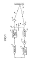
- Figure 1 illustrates schematically and in general terms a range measuring system according to the invention.
- FIG. 2 illustrates schematically one embodiment of the invention.
- FIG. 3 illustrates schematically another embodiment of the invention.
- Figure 4 is a histogram.
- the system shown in Figure 1 includes a laser 10, preferably a laser capable of producing a continuous wave output.
- the amplitude or frequency of the laser output may be altered by means of a modulator 11.
- the laser may include its own means of modulation which may consist of the alteration of a refractive index within the laser cavity by adjustment of an applied electric field.
- the electric field would in such an example be modulated at a frequency of the order of several hundred MHz where the system is used for the measurement of range of the order of a few metres.
- the light from the laser is passed through a beam splitter 12, such as a half-silvered mirror, and thence through an optical system represented by a lens 13 to provide a focused beam 14 that is directed towards a target, represented by a surface 15.
- a beam splitter 12 such as a half-silvered mirror
- an optical system represented by a lens 13 to provide a focused beam 14 that is directed towards a target, represented by a surface 15.
- Light 16 backscattered from the target passes through part of the optical system, as represented by lens 17, to be received by a demodulator or detector 18.
- the beam splitter provides reference light 19 which can be received by the detector when a suitable control means, such as a shutter 20, is operated.
- the reference light may be used for the extraction of the modulating signal and/or to provide a signal which indicates zero range.
- the output of the detector is passed through a non-inverting amplifier 21 and through a processing circuit 22 to provide an input to the modulating means represented by the modulator 11.
- the system is arranged so that the laser, the path of the optical beam, the detector and the path back to the laser form a closed regenerative loop which will oscillate, and modulate the laser light at a frequency such that there is at least a complete cycle of phase change at that frequency in the loop.
- the detector and/or the processing circuit should include some form of frequency selective means that restrict the frequency of oscillation to a selected frequency band, so as to avoid unwanted modes of oscillation and erroneous indications of range.
- phase shift and a propagation delay in the processing system, i.e. the system extending from the point of detection to the laser, some form of compensation for the phase shift is desirable in order that the oscillatory frequency with which the laser is modulated is properly representative of the range. This may be achieved by means of the shutter 20. In particular, a measurement of the oscillatory frequency may be made using light only from the laser (not reflected from the target). The phase shift and propagation delay exhibited as the composite phase shift will in practice provide a non zero modulating frequency at zero range and this frequency may be used as an offset in the measurement of actual range.
- Figure 2 illustrates in more detail a typical embodiment of the invention.
- Figure 3 illustrates a similar system and accordingly only Figure 2 will be described in detail.
- the output of the detector 18 is passed through a non inverting amplifier 21 and through a processing circuit 22 comprising a programmed filter 23 and a preprocessor 24 for the modulator 11.
- the system shown in Figure 2 includes for the amplifier 21 an automatic gain control circuit 25 which may be of known form.
- a processor unit 26 has a 'search command' input bus 27, a 'read' input line 28 and an output line 29.
- the processor unit 26 receives the automatic gain control signal from the AGC circuit 25 and provides an output on a data bus 33 to the programmed filter 23.
- a digital frequency meter 30 receives the output of the amplifier 21 and provides a further input to the processor.
- the programmed filter 23 is an analog band-pass filter which operates with a controllable centre frequency fo and a band width ⁇ f determined by the control processor 26.
- a zero range (fr) reference frequency is derived by preventing transmission of the laser to the target and causing the input to the detector to consist only of the reference light 19.
- Optical switching for this purpose is well known in the art and will not be descibed in any detail.
- the target is shown with two different surfaces 15a and 15b which provide on detection modulating frequencies f1 and f2 representing the effective ranges of the surfaces from the laser.
- the magnitude of the automatic gain control signal provides a measure the significance of the surface being measured.
- 'significance' is intended to refer to size or reflectivity.
- An input search command on bus 27 will specify a minimum and maximum range, within which reflected targets are to be sought, and a range interval to determine resolution.
- the processor 26 will calculate the corresponding frequency ranges and interval and will cause the filter 23 in the signal path to ramp at a suitable rate between one centre frequency limit and the other.
- the automatic gain control signal will be examined during the ramping of the search frequency to assess the magnitude and stability of any reflection and a histogram, such as is shown in Figure 4, of each corresponding range measurement may be developed to record a profile of reflective regions in the field of interest and their corresponding significance (reflectivity or magnitude).
- An appropriate 'read' command may be used to output either an individual range measurement or the complete histogram as required for any particular purpose.
- the dynamic range of signals will necessitate the use of an automatic gain control system and there will be a significant propagation delay and corresponding finite zero range frequency in a practical system.
- the combination of automatic gain control and the programmed filter may introduce a further variable in this delay. It is a straightforward matter using a controlled attenuator such as a wedge filter 32 and/or phase delay in the reference light path (as shown in Figure 3) to derive and store corresponding values of propagation delay and gain for various conditions. This may form a part of a self test or auto-calibration programme, carried out under control of the processor unit.
- the said values constitute system constants which are stored in memory 31 (as shown in Figure 3) as look-up tables. Data may be withdrawn from memory and used under normal measuring conditions to modify or refine the range measurements.
- the filter 23 may comprise any ordinary band-pass filter configuration, the operational components, such as capacitors, being switched in systematic manner in response to a parallel digital bus signal from the processor.
- a digital filter may be employed as the filter 23.
- a range finder may be constructed in order to measure ranges from, for example, 0.5 metres to 30 metres in 0.5 metre increments.
- the corresponding filter frequencies would be selectable over a range of 10cms to 30 metres with allowance for zero range propagation delays.
- These may be measured and stored for various settings of the light path attenuator covering the range of, for example, 70 decibels in 3 decibel steps.
- the system may be allowed to settle with a specific setting of the filter 23 and the range derived from a knowledge of the reference frequency for that filter setting, the automatic gain control level and the measured frequency of oscillation.
- the system oscillates at 10.5MHz with an automatic gain control level corresponding to a gain of 20 decibels, the band-pass filter 23 being centered on 10.25 MHz.
- the total delay due to the electronic signal path is 45 nanoseconds, including the delay of the amplifier 21 at a gain of 20 decibels.
- the total delay including the optical path is (1/10.5) x 10 ⁇ 6 seconds which is equal to 95.2 nanoseconds.
- the additional delay due to the optical path is accordingly 95.2 less 45 which is equal to 50.2 nanoseconds. This corresponds to a total distance of 16.7 metres or a reflecting surface at a range of 8.35 metres.
- transit time (total delay) - (delay in electronic path).
- the total delay is obtained as the reciprocal of the loop oscillation frequency.
- the delay in the electronic path depends in general on the oscillation frequency and the gain in the electronic signal path and may be derived and stored for a multiplicity of operating conditions in a calibration routine.
Landscapes
- Physics & Mathematics (AREA)
- Electromagnetism (AREA)
- Engineering & Computer Science (AREA)
- Computer Networks & Wireless Communication (AREA)
- General Physics & Mathematics (AREA)
- Radar, Positioning & Navigation (AREA)
- Remote Sensing (AREA)
- Optical Radar Systems And Details Thereof (AREA)
Applications Claiming Priority (2)
| Application Number | Priority Date | Filing Date | Title |
|---|---|---|---|
| GB8928714 | 1989-12-20 | ||
| GB898928714A GB8928714D0 (en) | 1989-12-20 | 1989-12-20 | Electro-optical devices |
Publications (2)
| Publication Number | Publication Date |
|---|---|
| EP0434191A2 true EP0434191A2 (de) | 1991-06-26 |
| EP0434191A3 EP0434191A3 (en) | 1992-06-03 |
Family
ID=10668212
Family Applications (1)
| Application Number | Title | Priority Date | Filing Date |
|---|---|---|---|
| EP19900311283 Withdrawn EP0434191A3 (en) | 1989-12-20 | 1990-10-16 | Electro-optical ranging systems |
Country Status (2)
| Country | Link |
|---|---|
| EP (1) | EP0434191A3 (de) |
| GB (2) | GB8928714D0 (de) |
Cited By (8)
| Publication number | Priority date | Publication date | Assignee | Title |
|---|---|---|---|---|
| EP0646766A2 (de) * | 1993-09-30 | 1995-04-05 | Fraunhofer-Gesellschaft Zur Förderung Der Angewandten Forschung E.V. | Verfahren und Anordnung zur Absolutinterferometrie mit durch Diodenlaser erzeugter Strahlung |
| FR2734645A1 (fr) * | 1995-05-22 | 1996-11-29 | Borre Sylvain | Metre a utilisation d'une diode laser pour mesures de precision dans le domaine du batiment et des travaux publics |
| EP0747727A2 (de) * | 1995-06-08 | 1996-12-11 | Erwin Sick GmbH Optik-Elektronik | Verfahren und Vorrichtung zur Abstandsmessung |
| WO1998023972A1 (fr) * | 1996-11-26 | 1998-06-04 | Precilaser | Metre a utilisation d'une diode laser pour mesures de precision |
| EP1262906A2 (de) * | 2001-05-29 | 2002-12-04 | Sick AG | Verfahren und Vorrichtung zur Abstandsbestimmung |
| DE10018948B4 (de) * | 1999-04-23 | 2004-02-05 | Leuze Electronic Gmbh + Co Kg | Optoelektronische Vorrichtung |
| US6852991B2 (en) | 2001-05-29 | 2005-02-08 | Sick Ag | Optoelectronic sensor with adjustable depth of field range |
| EP2450722A1 (de) * | 2010-11-09 | 2012-05-09 | Pepperl & Fuchs GmbH | Vorrichtung und Verfahren zum Bestimmen der Laufzeit einer Prüfstrahlung |
Citations (3)
| Publication number | Priority date | Publication date | Assignee | Title |
|---|---|---|---|---|
| DE1807237A1 (de) * | 1968-06-26 | 1970-04-23 | Jenoptik Jena Gmbh | Elektromagnetisches Streckenmessgeraet |
| EP0173087A1 (de) * | 1984-08-07 | 1986-03-05 | Erwin Sick GmbH Optik-Elektronik | Vorrichtung zur Messung der Laufzeit von elektromagnetischen Wellen |
| FR2601145A1 (fr) * | 1986-05-20 | 1988-01-08 | Simeray Janick | Telemetre a frequence accordee |
Family Cites Families (1)
| Publication number | Priority date | Publication date | Assignee | Title |
|---|---|---|---|---|
| GB2040131A (en) * | 1978-12-13 | 1980-08-20 | United Technologies Corp | Electrooptic instruments |
-
1989
- 1989-12-20 GB GB898928714A patent/GB8928714D0/en active Pending
-
1990
- 1990-10-11 GB GB9022096A patent/GB2239368B/en not_active Expired - Fee Related
- 1990-10-16 EP EP19900311283 patent/EP0434191A3/en not_active Withdrawn
Patent Citations (3)
| Publication number | Priority date | Publication date | Assignee | Title |
|---|---|---|---|---|
| DE1807237A1 (de) * | 1968-06-26 | 1970-04-23 | Jenoptik Jena Gmbh | Elektromagnetisches Streckenmessgeraet |
| EP0173087A1 (de) * | 1984-08-07 | 1986-03-05 | Erwin Sick GmbH Optik-Elektronik | Vorrichtung zur Messung der Laufzeit von elektromagnetischen Wellen |
| FR2601145A1 (fr) * | 1986-05-20 | 1988-01-08 | Simeray Janick | Telemetre a frequence accordee |
Non-Patent Citations (2)
| Title |
|---|
| ELECTRONICS AND COMMUNICATIONS IN JAPAN, PART 2 vol. 71, no. 11, 1988, pages 70 - 76; K. SATO ET AL.: 'Fundamental study on a short distance measurement method by using a sinusoidal wave oscillator with light path as delay line' * |
| ELECTRONICS. vol. 42, no. 11, 26 May 1969, NEW YORK US page 186; 'In the loop' * |
Cited By (13)
| Publication number | Priority date | Publication date | Assignee | Title |
|---|---|---|---|---|
| EP0646766A2 (de) * | 1993-09-30 | 1995-04-05 | Fraunhofer-Gesellschaft Zur Förderung Der Angewandten Forschung E.V. | Verfahren und Anordnung zur Absolutinterferometrie mit durch Diodenlaser erzeugter Strahlung |
| EP0646766A3 (de) * | 1993-09-30 | 1996-10-16 | Fraunhofer Ges Forschung | Verfahren und Anordnung zur Absolutinterferometrie mit durch Diodenlaser erzeugter Strahlung. |
| FR2734645A1 (fr) * | 1995-05-22 | 1996-11-29 | Borre Sylvain | Metre a utilisation d'une diode laser pour mesures de precision dans le domaine du batiment et des travaux publics |
| EP0747727A2 (de) * | 1995-06-08 | 1996-12-11 | Erwin Sick GmbH Optik-Elektronik | Verfahren und Vorrichtung zur Abstandsmessung |
| EP0747727A3 (de) * | 1995-06-08 | 1998-07-22 | Sick Ag | Verfahren und Vorrichtung zur Abstandsmessung |
| WO1998023972A1 (fr) * | 1996-11-26 | 1998-06-04 | Precilaser | Metre a utilisation d'une diode laser pour mesures de precision |
| DE10018948B4 (de) * | 1999-04-23 | 2004-02-05 | Leuze Electronic Gmbh + Co Kg | Optoelektronische Vorrichtung |
| DE10126087A1 (de) * | 2001-05-29 | 2002-12-05 | Sick Ag | Verfahren und Vorrichtung zur Abstandsbestimmung |
| EP1262906A3 (de) * | 2001-05-29 | 2003-12-17 | Sick AG | Verfahren und Vorrichtung zur Abstandsbestimmung |
| EP1262906A2 (de) * | 2001-05-29 | 2002-12-04 | Sick AG | Verfahren und Vorrichtung zur Abstandsbestimmung |
| US6765393B2 (en) | 2001-05-29 | 2004-07-20 | Sick, Ag | Method and an apparatus for determining distance |
| US6852991B2 (en) | 2001-05-29 | 2005-02-08 | Sick Ag | Optoelectronic sensor with adjustable depth of field range |
| EP2450722A1 (de) * | 2010-11-09 | 2012-05-09 | Pepperl & Fuchs GmbH | Vorrichtung und Verfahren zum Bestimmen der Laufzeit einer Prüfstrahlung |
Also Published As
| Publication number | Publication date |
|---|---|
| GB8928714D0 (en) | 1990-11-21 |
| GB2239368B (en) | 1994-04-27 |
| EP0434191A3 (en) | 1992-06-03 |
| GB9022096D0 (en) | 1990-11-21 |
| GB2239368A (en) | 1991-06-26 |
Similar Documents
| Publication | Publication Date | Title |
|---|---|---|
| CA1084148A (en) | Electro-optical ranging system for distance measurements to moving targets | |
| US5737085A (en) | Precision optical displacement measurement system | |
| US5610705A (en) | Doppler velocimeter | |
| JP5401412B2 (ja) | 光スイッチを備える絶対距離計 | |
| EP0721595B1 (de) | Lasersensor, mit der möglichkeit der messung von entfernung, geschwindigkeit und beschleunigung | |
| KR900002200B1 (ko) | 탐사방법 및 장치 | |
| US5400034A (en) | Digital phase lock detector | |
| US4240745A (en) | Imagery with constant range lines | |
| CA2337026A1 (en) | Laser displacement measurement system | |
| US2966090A (en) | Optical distance measuring device | |
| JPS5965221A (ja) | ダイオ−ドレ−ザおよび光フアイバ−を使用するタンクレベルのゲ−ジング方法および装置 | |
| EP0434191A2 (de) | Elektrooptische Systeme zur Abstandsmessung | |
| US6133993A (en) | Length and velocity measurement apparatus | |
| US4861158A (en) | Chirp and Doppler optical gauge | |
| US5914683A (en) | Ultra high resolution ranging unit | |
| US4319245A (en) | Doppler signal processing apparatus | |
| US4861159A (en) | Dynamic doppler optical gauge | |
| US6628402B1 (en) | Phase interference detecting method and system in interferometer, and light detector therefor | |
| US3602594A (en) | Laser calibration of large radio reflector | |
| US5007731A (en) | Doppler fluid flow velocity measuring apparatus and method utilizing imaging of scattered light | |
| CN115308715A (zh) | 一种稀疏调制测风雷达的方法和系统 | |
| JP3241857B2 (ja) | 光学式距離計 | |
| CA1218867A (en) | Method and apparatus for optical tank gauging | |
| JP3236941B2 (ja) | 光波距離計における測距方法 | |
| JP2930740B2 (ja) | サーボスロープ式fm−cwレーダ |
Legal Events
| Date | Code | Title | Description |
|---|---|---|---|
| PUAI | Public reference made under article 153(3) epc to a published international application that has entered the european phase |
Free format text: ORIGINAL CODE: 0009012 |
|
| AK | Designated contracting states |
Kind code of ref document: A2 Designated state(s): BE DE FR IT |
|
| PUAL | Search report despatched |
Free format text: ORIGINAL CODE: 0009013 |
|
| AK | Designated contracting states |
Kind code of ref document: A3 Designated state(s): BE DE FR IT |
|
| STAA | Information on the status of an ep patent application or granted ep patent |
Free format text: STATUS: THE APPLICATION IS DEEMED TO BE WITHDRAWN |
|
| 18D | Application deemed to be withdrawn |
Effective date: 19921204 |