EP0433920A1 - Apparatus for manufacturing and feeding tyre beads on to an automotive tyre building drum - Google Patents
Apparatus for manufacturing and feeding tyre beads on to an automotive tyre building drum Download PDFInfo
- Publication number
- EP0433920A1 EP0433920A1 EP90124265A EP90124265A EP0433920A1 EP 0433920 A1 EP0433920 A1 EP 0433920A1 EP 90124265 A EP90124265 A EP 90124265A EP 90124265 A EP90124265 A EP 90124265A EP 0433920 A1 EP0433920 A1 EP 0433920A1
- Authority
- EP
- European Patent Office
- Prior art keywords
- annular bodies
- annular
- segments
- slide
- supporting element
- Prior art date
- Legal status (The legal status is an assumption and is not a legal conclusion. Google has not performed a legal analysis and makes no representation as to the accuracy of the status listed.)
- Granted
Links
Images


Classifications
-
- B—PERFORMING OPERATIONS; TRANSPORTING
- B29—WORKING OF PLASTICS; WORKING OF SUBSTANCES IN A PLASTIC STATE IN GENERAL
- B29D—PRODUCING PARTICULAR ARTICLES FROM PLASTICS OR FROM SUBSTANCES IN A PLASTIC STATE
- B29D30/00—Producing pneumatic or solid tyres or parts thereof
- B29D30/06—Pneumatic tyres or parts thereof (e.g. produced by casting, moulding, compression moulding, injection moulding, centrifugal casting)
- B29D30/08—Building tyres
- B29D30/10—Building tyres on round cores, i.e. the shape of the core is approximately identical with the shape of the completed tyre
- B29D30/18—Fitting the bead-rings or bead-cores; Folding the textile layers around the rings or cores
-
- B—PERFORMING OPERATIONS; TRANSPORTING
- B29—WORKING OF PLASTICS; WORKING OF SUBSTANCES IN A PLASTIC STATE IN GENERAL
- B29D—PRODUCING PARTICULAR ARTICLES FROM PLASTICS OR FROM SUBSTANCES IN A PLASTIC STATE
- B29D30/00—Producing pneumatic or solid tyres or parts thereof
- B29D30/06—Pneumatic tyres or parts thereof (e.g. produced by casting, moulding, compression moulding, injection moulding, centrifugal casting)
- B29D30/48—Bead-rings or bead-cores; Treatment thereof prior to building the tyre
-
- B—PERFORMING OPERATIONS; TRANSPORTING
- B29—WORKING OF PLASTICS; WORKING OF SUBSTANCES IN A PLASTIC STATE IN GENERAL
- B29D—PRODUCING PARTICULAR ARTICLES FROM PLASTICS OR FROM SUBSTANCES IN A PLASTIC STATE
- B29D30/00—Producing pneumatic or solid tyres or parts thereof
- B29D30/06—Pneumatic tyres or parts thereof (e.g. produced by casting, moulding, compression moulding, injection moulding, centrifugal casting)
- B29D30/08—Building tyres
- B29D30/20—Building tyres by the flat-tyre method, i.e. building on cylindrical drums
- B29D30/32—Fitting the bead-rings or bead-cores; Folding the textile layers around the rings or cores
-
- B—PERFORMING OPERATIONS; TRANSPORTING
- B29—WORKING OF PLASTICS; WORKING OF SUBSTANCES IN A PLASTIC STATE IN GENERAL
- B29D—PRODUCING PARTICULAR ARTICLES FROM PLASTICS OR FROM SUBSTANCES IN A PLASTIC STATE
- B29D30/00—Producing pneumatic or solid tyres or parts thereof
- B29D30/0016—Handling tyres or parts thereof, e.g. supplying, storing, conveying
- B29D2030/0044—Handling tyre beads, e.g., storing, transporting, transferring and supplying to the toroidal support or to the drum
-
- B—PERFORMING OPERATIONS; TRANSPORTING
- B29—WORKING OF PLASTICS; WORKING OF SUBSTANCES IN A PLASTIC STATE IN GENERAL
- B29D—PRODUCING PARTICULAR ARTICLES FROM PLASTICS OR FROM SUBSTANCES IN A PLASTIC STATE
- B29D30/00—Producing pneumatic or solid tyres or parts thereof
- B29D30/06—Pneumatic tyres or parts thereof (e.g. produced by casting, moulding, compression moulding, injection moulding, centrifugal casting)
- B29D30/08—Building tyres
- B29D30/20—Building tyres by the flat-tyre method, i.e. building on cylindrical drums
- B29D30/32—Fitting the bead-rings or bead-cores; Folding the textile layers around the rings or cores
- B29D2030/3207—Positioning the beads
-
- B—PERFORMING OPERATIONS; TRANSPORTING
- B29—WORKING OF PLASTICS; WORKING OF SUBSTANCES IN A PLASTIC STATE IN GENERAL
- B29D—PRODUCING PARTICULAR ARTICLES FROM PLASTICS OR FROM SUBSTANCES IN A PLASTIC STATE
- B29D30/00—Producing pneumatic or solid tyres or parts thereof
- B29D30/06—Pneumatic tyres or parts thereof (e.g. produced by casting, moulding, compression moulding, injection moulding, centrifugal casting)
- B29D30/48—Bead-rings or bead-cores; Treatment thereof prior to building the tyre
- B29D2030/487—Forming devices for manufacturing the beads
Definitions
- the present invention relates to an apparatus for manufacturing and feeding tire beads on to an automotive tire building drum.
- the present invention relates to an apparatus for manufacturing and automatically feeding on to a tire building drum pairs of beads preferably, but not exclusively, of the type described and claimed in copending Italian Patent Application n. 68169-A/89, the content of which is fully incorporated herein, and which relates to an automotive tire bead consisting of a substantially circular-section annular element formed from a first wire, usually a continuous metal cable, wound in such a manner as to form a number of packed coils. Said coils are arranged over the substantially circular section of said annular element according to a given law, and are held together by a second non-metal wire or yarn of heat-shrinkable material coiled about said annular element.
- an apparatus for manufacturing automotive tire beads comprising two mobile mandrels for forming respective said beads; characterized in that each said mandrel comprises an inner drum for winding a continuous metal wire constituting a respective said bead, and an outer device for housing and gripping said bead; each said inner drum comprising an inner ring consisting of two coaxial annular bodies, a first supporting element for each said annular body, first actuating means for moving said two first supporting elements between a first position, wherein said two annular bodies are mated, and a second position wherein said two annular bodies are axially detached; each said outer device for housing and gripping said bead comprising a second supporting element, an outer ring comprising a number of segments carried on said second supporting element, second actuating means for moving said segments radially in relation to said second supporting element, and third actuating means for moving said second supporting element both transversely, between a third position wherein said outer ring is coaxial with said two annular
- Each said annular body is preferably mounted for rotation on said respective first supporting element; fifth actuating means being provided for turning said annular bodies about a common axis in relation to said respective first supporting elements.
- FIGURE 1 shows a schematic front view of a preferred embodiment of the apparatus according to the present invention in the final operating position
- FIGURES 2 to 6 show schematic top plan views, with parts removed for simplicity, of the FIGURE 1 apparatus in various operating positions;
- FIGURE 7 shows a section along line VII-VII in FIGURE 1;
- FIGURE 8 shows a section along line VIII-VIII in FIGURE 4.
- FIGURE 9 shows a section along line IX-IX in FIGURE 5;
- FIGURE 10 shows a section along line X-X in FIGURE 4.
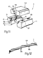
- FIGURE 11 shows an exploded part view in perspective of a preferred embodiment of a detail on the FIGURE 1 apparatus
- FIGURE 12 shows a partial side view of the bead formed on the FIGURE 11 apparatus.
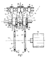
- FIGURE 1 indicates an apparatus for manufacturing automotive tire beads 2.
- Apparatus 1 comprises a pair of mandrels 3, numbered respectively 3a and 3b, for forming respective beads 2, and running along a pair of parallel, substantially horizontal guides 4 and 5.
- Each mandrel 3 comprises an inner drum 6 for winding a continuous metal wire 7 constituting a respective bead 2, and an outer device 8 for housing and gripping finished bead 2.
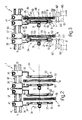
- each inner drum 6 comprises an inner ring 9 consisting of two annular bodies 10 and 11 having a common axis 12 parallel to guides 4 and 5 and lying substantially in the same horizontal plane defined by the same.
- Annular bodies 10 and 11 are substantially cylindrical, and each is defined by a substantially cylindrical outer surface 13, a substantially cylindrical inner surface 14 coaxial with outer surface 13, and an annular outer lateral surface 15.
- Annular bodies 10 and 11 are also defined by respective inner annular lateral surfaces 16 and 17 designed to mate with each other; said surface 16 presenting an annular groove 18 coaxial with axis 12 and of substantially trapezoidal section; and said surface 17 presenting an annular centering rib 19 having a section designed to engage and mate with groove 18.
- each annular body 10 and 11 presents an annular groove having a section substantially in the form of a quarter arc of a circle, and defining, with the corresponding groove on the other annular body 11 and 10, and when surfaces 16 and 17 are arranged contacting each other, an annular groove 20 extending along the center line of inner ring 9 and designed to receive part of bead 2, the remainder of which extends radially outwards of inner ring 9.
- Drum 6 also comprises two supporting elements or annular supports 21 and 22 respectively supporting annular bodies 10 and 11 in rotary manner, and each comprising a tubular body 23 connected to surface 14 of respective annular body 10, 11 via the interposition of a bearing 24, and an outer radial end flange 25 connected to surface 15 of respective annular body 10, 11 via the interposition of a bearing 26.
- Tubular body 23 of annular support 21 presents an inner radial appendix 27 having an outer cavity 28 parallel to axis 12 and housing a pinion 29 fitted on to the output shaft 30 of a motor 31 parallel to axis 12 and supported on annular support 21.
- a slot 32 formed through tubular body 23 of annular support 21 at cavity 28 enables pinion 29 to engage a ring gear 33 extending radially inwards from surface 14 of annular body 10.
- Annular supports 21 and 22 present respective substantially L-shaped outer brackets 34 and 35 whereby they are connected integral to respective slides 36 and 37 running along guides 4 and 5.
- each slide 36, 37 presents two through holes 38 and 39 engaged in sliding manner by guides 4 and 5.
- guide 4 presents an outer rack 40
- each of slides 36 and 37 supports a reversible electric motor 41 driving a respective sprocket (not shown) engaging rack 40 for moving respective slide 36, 37 along guides 4 and 5 between a first position, wherein annular bodies 10 and 11 are mated, and a second position wherein annular bodies 10 and 11 are detached axially.
- one of slides 36, 37 is mounted in a fixed position on guides 4 and 5, whereas the other is powered for moving respective annular body 10, 11 in relation to the other annular body 11, 10 between said two positions.
- devices 8 comprise a common guide 42 parallel to guides 4 and 5, extending along an axis 43 parallel to axis 12, and defining, with axis 12, a plane perpendicular to that defined by guides 4 and 5.
- Guide 42 presents a substantially square section, and each device 8 comprises a slide 44 connected prismatically to guide 42, and supporting a reversible electric motor 45 connected to guide 42 via a rack-and-pinion connection 46 for moving slide 44 both ways along guide 42.
- slide 44 there is mounted for rotation a tubular body 47, the angular position of which in relation to slide 44 is regulated by a reversible electric motor 48 connected to slide 44 via a worm-and-helical-gear connection 49 for turning tubular body 47 about axis 43 and both ways in relation to slide 44.
- a reversible electric motor 48 connected to slide 44 via a worm-and-helical-gear connection 49 for turning tubular body 47 about axis 43 and both ways in relation to slide 44.
- a radial column 50 is connected integral with the outer surface of tubular body 47, the other end of which column 50 is connected to the outer surface of an annular support 51 supporting an outer ring 52.
- Annular support 51 is powered by motor 48 so as to move between a first position, wherein ring 52 is coaxial with axis 12, and a second position wherein ring 52 is coaxial with axis 53 of a known tire building drum 54.
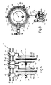
- outer ring 52 consists of three segments 55, each connected (FIGURE 10) to the output rod 56 of a respective hydraulic or pneumatic jack 57 supported on annular support 51 for moving respective segment 55 between a contracted position, wherein the ends of segments 55 substantially contact one another, and an expanded position wherein segments 55 are detached and substantially contact the inner surface of annular support 51.
- segments 55 When contracted, segments 55 define ring 52, which presents a substantially cylindrical inner surface 58 of substantially the same diameter as surface 13. Along the center line of surface 58, there is formed an annular groove 59 extending over all of segments 55, of substantially semicircular section, and of the same diameter as groove 20.
- slides 36 and 37 are so positioned on guides 4 and 5 as to maintain annular bodies 10 and 11 separated by a distance at least equal to the thickness of outer ring 52 and annular support 51, which is positioned coaxial with axis 12 of annular bodies 10 and 11.
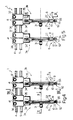
- slide 37 is then moved towards slide 36 so as to move bracket 35, together with annular support 22 and annular body 11, forward through outer ring 52, and so bring annular body 11 into contact with annular body 10.
- slide 36 is then moved, together with slide 37, so as to move inner ring 9 in relation to outer ring 52 and so uncover groove 20 and prevent access to the same from being impeded by outer ring 52.
- One end of metal wire 7 is then secured, in any known manner, to ring 9 and inside groove 20, and motor 21 is activated for turning inner ring 9 about axis 12 and so coiling wire 7 along groove 20.
- wire 7 which is normally fed off a reel 60, is fed about a pulley 61 and into groove 20 through a known type of control unit 62 having an oscillating guide member 63 engaged by wire 7 and designed to oscillate, by virtue of a computer (not shown), in such a manner as to arrange wire 7 in coils extending along groove 20 and arranged in a given order in relation to one another.
- a computer not shown
- annular support 51 As shown in FIGURE 4, via operation of motor 45, annular support 51, with segments 55 in the expanded position, is then moved along axis 12 and outwards of ring 9, after which (FIGURE 5), segments 55 are contracted so as to form ring 52 and receive, inside groove 59 of ring 52, the portion of bead 2 projecting outwards of groove 20.
- motors 41 are activated for separating annular bodies 10 and 11 and so releasing finished bead 2 inside groove 59 of outer ring 52.
- motor 48 is then activated for moving annular support 51 transversely from its current position coaxial with axis 12 into a position wherein it is coaxial with axis 53 of tire building drum 54.
- Motor 45 is then operated for moving annular support 51, together with outer ring 52 and bead 2 housed inside the same, axially along axis 53, and so setting bead 2 in the assembly position on tire building drum 54.
- Bead 2 produced on apparatus 1 as described above may be any known type of "program” bead or, preferably, as already stated, of the type described and claimed in copending Italian Patent Application n. 68168-A/89, and numbered 64 in FIGURE 12.
- bead 64 is of substantially circular section, and is formed by winding wire 7 in such a manner as to form coils 65 packed together by a coiled outer non-metal wire or yarn 66 of heat-shrinkable material.
- Bead 64 as described above is produced on apparatus 1 using mandrels 3 as shown schematically in FIGURE 11 and as described in copending Italian Patent Application n. 68169-A/89, the content of which is fully incorporated herein.
- mandrel 3 in FIGURE 11 defines a circular duct consisting of grooves 20 and 58, for receiving coils 65 formed by wire 7; and a duct 67 coiled about said duct 20-58 and comprising portions 68 formed through annular body 10, portions 69 formed through annular body 11, and portions 70 formed through outer ring 52.
- portions 68, 69 and 70 define duct 67 along which wire 66 is blown as described in the aforementioned Italian Patent Application n. 69169-A/89.
- Wire 66 is brought into contact with coils 65 via a slot 71 extending over the entire length of duct 67 and located between duct 67 and the duct defined by grooves 20 and 58.
Abstract

Description
- The present invention relates to an apparatus for manufacturing and feeding tire beads on to an automotive tire building drum.
- In particular, the present invention relates to an apparatus for manufacturing and automatically feeding on to a tire building drum pairs of beads preferably, but not exclusively, of the type described and claimed in copending Italian Patent Application n. 68169-A/89, the content of which is fully incorporated herein, and which relates to an automotive tire bead consisting of a substantially circular-section annular element formed from a first wire, usually a continuous metal cable, wound in such a manner as to form a number of packed coils. Said coils are arranged over the substantially circular section of said annular element according to a given law, and are held together by a second non-metal wire or yarn of heat-shrinkable material coiled about said annular element.
- According to the present invention, there is provided an apparatus for manufacturing automotive tire beads, and comprising two mobile mandrels for forming respective said beads; characterized in that each said mandrel comprises an inner drum for winding a continuous metal wire constituting a respective said bead, and an outer device for housing and gripping said bead; each said inner drum comprising an inner ring consisting of two coaxial annular bodies, a first supporting element for each said annular body, first actuating means for moving said two first supporting elements between a first position, wherein said two annular bodies are mated, and a second position wherein said two annular bodies are axially detached; each said outer device for housing and gripping said bead comprising a second supporting element, an outer ring comprising a number of segments carried on said second supporting element, second actuating means for moving said segments radially in relation to said second supporting element, and third actuating means for moving said second supporting element both transversely, between a third position wherein said outer ring is coaxial with said two annular bodies, and a fourth position wherein said outer ring is coaxial with a tire building drum, and axially along said tire building drum.
- Each said annular body is preferably mounted for rotation on said respective first supporting element; fifth actuating means being provided for turning said annular bodies about a common axis in relation to said respective first supporting elements.
- The invention will now be described by way of example with reference to the accompanying drawings, in which:
- FIGURE 1 shows a schematic front view of a preferred embodiment of the apparatus according to the present invention in the final operating position;
- FIGURES 2 to 6 show schematic top plan views, with parts removed for simplicity, of the FIGURE 1 apparatus in various operating positions;
- FIGURE 7 shows a section along line VII-VII in FIGURE 1;
- FIGURE 8 shows a section along line VIII-VIII in FIGURE 4;
- FIGURE 9 shows a section along line IX-IX in FIGURE 5;
- FIGURE 10 shows a section along line X-X in FIGURE 4;
- FIGURE 11 shows an exploded part view in perspective of a preferred embodiment of a detail on the FIGURE 1 apparatus;
- FIGURE 12 shows a partial side view of the bead formed on the FIGURE 11 apparatus.
- Numeral 1 in FIGURE 1 indicates an apparatus for manufacturing
automotive tire beads 2. - Apparatus 1 comprises a pair of
mandrels 3, numbered respectively 3a and 3b, for formingrespective beads 2, and running along a pair of parallel, substantiallyhorizontal guides - Each
mandrel 3 comprises aninner drum 6 for winding a continuous metal wire 7 constituting arespective bead 2, and anouter device 8 for housing and gripping finishedbead 2. - As shown in FIGURE 10, each
inner drum 6 comprises aninner ring 9 consisting of twoannular bodies common axis 12 parallel toguides Annular bodies outer surface 13, a substantially cylindricalinner surface 14 coaxial withouter surface 13, and an annular outerlateral surface 15.Annular bodies lateral surfaces 16 and 17 designed to mate with each other; saidsurface 16 presenting anannular groove 18 coaxial withaxis 12 and of substantially trapezoidal section; and said surface 17 presenting anannular centering rib 19 having a section designed to engage and mate withgroove 18. - At the radius between
surfaces annular body 10 andsurfaces 13 and 17 onannular body 11, eachannular body annular body surfaces 16 and 17 are arranged contacting each other, anannular groove 20 extending along the center line ofinner ring 9 and designed to receive part ofbead 2, the remainder of which extends radially outwards ofinner ring 9. -
Drum 6 also comprises two supporting elements orannular supports annular bodies tubular body 23 connected tosurface 14 of respectiveannular body bearing 24, and an outerradial end flange 25 connected tosurface 15 of respectiveannular body bearing 26. -
Tubular body 23 ofannular support 21 presents an innerradial appendix 27 having anouter cavity 28 parallel toaxis 12 and housing apinion 29 fitted on to theoutput shaft 30 of amotor 31 parallel toaxis 12 and supported onannular support 21. Aslot 32 formed throughtubular body 23 ofannular support 21 atcavity 28 enablespinion 29 to engage aring gear 33 extending radially inwards fromsurface 14 ofannular body 10. -
Annular supports outer brackets respective slides guides slide holes 38 and 39 engaged in sliding manner byguides guide 4 presents anouter rack 40, and each ofslides electric motor 41 driving a respective sprocket (not shown) engagingrack 40 for movingrespective slide guides annular bodies annular bodies - According to a variation (not shown), one of
slides guides annular body annular body - As shown in FIGURES 1 and 7,
devices 8 comprise acommon guide 42 parallel toguides axis 43 parallel toaxis 12, and defining, withaxis 12, a plane perpendicular to that defined byguides Guide 42 presents a substantially square section, and eachdevice 8 comprises aslide 44 connected prismatically to guide 42, and supporting a reversibleelectric motor 45 connected toguide 42 via a rack-and-pinion connection 46 for movingslide 44 both ways alongguide 42. Aboutslide 44, there is mounted for rotation atubular body 47, the angular position of which in relation toslide 44 is regulated by a reversibleelectric motor 48 connected toslide 44 via a worm-and-helical-gear connection 49 for turningtubular body 47 aboutaxis 43 and both ways in relation toslide 44. - One end of a
radial column 50 is connected integral with the outer surface oftubular body 47, the other end of whichcolumn 50 is connected to the outer surface of anannular support 51 supporting anouter ring 52.Annular support 51 is powered bymotor 48 so as to move between a first position, whereinring 52 is coaxial withaxis 12, and a second position whereinring 52 is coaxial withaxis 53 of a knowntire building drum 54. - As shown in FIGURES 7 and 8,
outer ring 52 consists of threesegments 55, each connected (FIGURE 10) to theoutput rod 56 of a respective hydraulic orpneumatic jack 57 supported onannular support 51 for movingrespective segment 55 between a contracted position, wherein the ends ofsegments 55 substantially contact one another, and an expanded position whereinsegments 55 are detached and substantially contact the inner surface ofannular support 51. When contracted,segments 55 definering 52, which presents a substantially cylindricalinner surface 58 of substantially the same diameter assurface 13. Along the center line ofsurface 58, there is formed anannular groove 59 extending over all ofsegments 55, of substantially semicircular section, and of the same diameter asgroove 20. - As operation and timing of both
mandrels 3 are identical, operation of device 1 will be described with reference tomandrel 3a and commencing from the starting position shown in FIGURE 1. - To begin with,
slides guides annular bodies outer ring 52 andannular support 51, which is positioned coaxial withaxis 12 ofannular bodies - As shown in FIGURE 3,
slide 37 is then moved towardsslide 36 so as to movebracket 35, together withannular support 22 andannular body 11, forward throughouter ring 52, and so bringannular body 11 into contact withannular body 10. If necessary,slide 36 is then moved, together withslide 37, so as to moveinner ring 9 in relation toouter ring 52 and souncover groove 20 and prevent access to the same from being impeded byouter ring 52. One end of metal wire 7 is then secured, in any known manner, to ring 9 and insidegroove 20, andmotor 21 is activated for turninginner ring 9 aboutaxis 12 and so coiling wire 7 alonggroove 20. - As shown in FIGURE 3, wire 7, which is normally fed off a
reel 60, is fed about apulley 61 and intogroove 20 through a known type ofcontrol unit 62 having anoscillating guide member 63 engaged by wire 7 and designed to oscillate, by virtue of a computer (not shown), in such a manner as to arrange wire 7 in coils extending alonggroove 20 and arranged in a given order in relation to one another. Once wound, wire 7 is cut, and the finishedbead 2 presents a given section, part of which is housed insidegroove 20 and the remainder of which projects radially outwards ofinner ring 9. - As shown in FIGURE 4, via operation of
motor 45,annular support 51, withsegments 55 in the expanded position, is then moved alongaxis 12 and outwards ofring 9, after which (FIGURE 5),segments 55 are contracted so as to formring 52 and receive, insidegroove 59 ofring 52, the portion ofbead 2 projecting outwards ofgroove 20. - At this point (FIGURE 6),
motors 41 are activated for separatingannular bodies bead 2 insidegroove 59 ofouter ring 52. - As shown in FIGURES 7 and 1,
motor 48 is then activated for movingannular support 51 transversely from its current position coaxial withaxis 12 into a position wherein it is coaxial withaxis 53 oftire building drum 54. Motor 45 is then operated for movingannular support 51, together withouter ring 52 andbead 2 housed inside the same, axially alongaxis 53, and so settingbead 2 in the assembly position ontire building drum 54. - Successive operation of
jacks 57 andmotors segments 55, thus releasingbead 2 on totire building drum 54, and for restoringannular support 51 to the cycle start position in FIGURE 2. -
Bead 2 produced on apparatus 1 as described above may be any known type of "program" bead or, preferably, as already stated, of the type described and claimed in copending Italian Patent Application n. 68168-A/89, and numbered 64 in FIGURE 12. - As shown in FIGURE 12,
bead 64 is of substantially circular section, and is formed by winding wire 7 in such a manner as to formcoils 65 packed together by a coiled outer non-metal wire oryarn 66 of heat-shrinkable material. -
Bead 64 as described above is produced on apparatus 1 usingmandrels 3 as shown schematically in FIGURE 11 and as described in copending Italian Patent Application n. 68169-A/89, the content of which is fully incorporated herein. - When
annular bodies segments 55 are arranged contacting as shown in FIGURE 5,mandrel 3 in FIGURE 11 defines a circular duct consisting ofgrooves coils 65 formed by wire 7; and aduct 67 coiled about said duct 20-58 and comprising portions 68 formed throughannular body 10,portions 69 formed throughannular body 11, andportions 70 formed throughouter ring 52. - When
annular bodies outer ring 52 are arranged contacting as shown in FIGURE 5,portions duct 67 along whichwire 66 is blown as described in the aforementioned Italian Patent Application n. 69169-A/89.Wire 66 is brought into contact withcoils 65 via aslot 71 extending over the entire length ofduct 67 and located betweenduct 67 and the duct defined bygrooves
Claims (7)
- An apparatus (1) for manufacturing automotive tire beads (2), and comprising two mobile mandrels (3) for forming respective said beads (2); characterized in that each said mandrel (3) comprises an inner drum (6) for winding a continuous metal wire (7) constituting a respective said bead (2), and an outer device (8) for housing and gripping said bead (2); each said inner drum (6) comprising an inner ring (9) consisting of two coaxial annular bodies (10, 11), a first supporting element (21)(22) for each said annular body (10)(11), first actuating means (41) for moving said two first supporting elements (21, 22) between a first position, wherein said two annular bodies (10, 11) are mated, and a second position wherein said two annular bodies (10, 11) are axially detached; each said outer device (8) for housing and gripping said bead (2) comprising a second supporting element (51), an outer ring (52) comprising a number of segments (55) carried on said second supporting element (51), second actuating means (57) for moving said segments (55) radially in relation to said second supporting element (51), and third actuating means (46, 48) for moving said second supporting element (51) both transversely, between a third position wherein said outer ring (52) is coaxial with said two annular bodies (10, 11), and a fourth position wherein said outer ring (52) is coaxial with a tire building drum (54), and axially along said tire building drum (54).
- An apparatus as claimed in Claim 1, characterized in that each said annular body (10)(11) is mounted for rotation on said respective first supporting element (21)(22); fifth actuating means (31) being provided for turning said annular bodies (10, 11) about a common axis (12) in relation to said respective first supporting elements (21, 22).
- An apparatus as claimed in Claim 1 or 2, characterized by further comprising a first slide (36)(37) integral with each said first supporting element (21)(22); and first guide means (4, 5) extending parallel to the common axis (12) of said annular bodies (10, 11) and connected to said first slides (36, 37); said first actuating means (41) being carried by each said first slide (36)(37) for moving the same (36)(37) along said first guide means (4, 5) and said respective first supporting elements (21, 22) between said first and second positions.
- An apparatus as claimed in any one of the foregoing Claims, characterized by further comprising a second slide (44) supporting a respective said outer device (8); and second guide means (42) extending parallel to the common axis (12) of said annular bodies (10, 11) and to the axis (53) of said tire building drum (54), and connected to said second slides (44); said third actuating means (45, 48) being carried by each said second slide (44).
- An apparatus as claimed in Claim 4, characterized in that said third actuating means (45, 48) comprise a first (48) and second (45) reversible motor; each said outer device (8) being connected to a respective said second slide (44) so as to turn in relation to the same (44) about said second guide means (42) and, by virtue of said first motor (48), between said third and fourth positions, and so as to travel with said respective second slide (44) along said second guide means (42) by virtue of said second motor (45).
- An apparatus as claimed in any one of the foregoing Claims, characterized in that said annular bodies (10, 11) present respective outer circumferential grooves (20), and said segments (55) present respective portions of an inner circumferential groove (58); said grooves (20, 58) defining, when said annular bodies (10, 11) and said segments (55) are arranged contacting, with said annular bodies (10, 11) in said first position and said segments (55) contacting the outer surface of said annular bodies (10, 11), a first circular duct (20-58) for receiving a number of coils (65) of said metal wire (7).
- An apparatus as claimed in Claim 6, characterized in that said annular bodies (10, 11) and said segments (55) present respective portions (68, 69, 70) of a second duct (67) coiled about said first duct (20-58) and engaged by a non-metal wire (66) of heat-shrinkable material wound about said coils (65); a slot (71) extending over the entire length of said second duct (67) enabling communication between said first and second ducts (20-58, 67).
Applications Claiming Priority (2)
| Application Number | Priority Date | Filing Date | Title |
|---|---|---|---|
| IT06817189A IT1237737B (en) | 1989-12-22 | 1989-12-22 | APPARATUS FOR THE REALIZATION OF HEELS, AND FOR THE SUPPLY OF THEMSELVES TO A TIRE DRUMING TIRE FOR MOTOR VEHICLES. |
| IT6817189 | 1989-12-22 |
Publications (2)
| Publication Number | Publication Date |
|---|---|
| EP0433920A1 true EP0433920A1 (en) | 1991-06-26 |
| EP0433920B1 EP0433920B1 (en) | 1994-08-24 |
Family
ID=11308316
Family Applications (1)
| Application Number | Title | Priority Date | Filing Date |
|---|---|---|---|
| EP90124265A Expired - Lifetime EP0433920B1 (en) | 1989-12-22 | 1990-12-14 | Apparatus for manufacturing and feeding tyre beads on to an automotive tyre building drum |
Country Status (9)
| Country | Link |
|---|---|
| US (1) | US5141590A (en) |
| EP (1) | EP0433920B1 (en) |
| JP (1) | JPH0429836A (en) |
| KR (1) | KR910011440A (en) |
| BR (1) | BR9006438A (en) |
| CA (1) | CA2028482C (en) |
| DE (1) | DE69011826T2 (en) |
| ES (1) | ES2058743T3 (en) |
| IT (1) | IT1237737B (en) |
Cited By (2)
| Publication number | Priority date | Publication date | Assignee | Title |
|---|---|---|---|---|
| EP0995584A1 (en) * | 1998-04-07 | 2000-04-26 | Bridgestone Corporation | Bead wire winding device and method |
| WO2006003057A1 (en) * | 2004-07-06 | 2006-01-12 | Continental Aktiengesellschaft | Method and device for positioning bead wires |
Families Citing this family (2)
| Publication number | Priority date | Publication date | Assignee | Title |
|---|---|---|---|---|
| US6630045B1 (en) * | 1999-03-25 | 2003-10-07 | The Goodyear Tire & Rubber Company | Combined bead loading and apex application system |
| WO2003061954A1 (en) * | 2001-12-27 | 2003-07-31 | Gian Luigi Bosio | Tyre building apparatus |
Citations (2)
| Publication number | Priority date | Publication date | Assignee | Title |
|---|---|---|---|---|
| DE3509025A1 (en) * | 1985-03-13 | 1986-09-25 | Vsesojuznyj naučno-issledovatel'skij i konstruktorskij institut po oborudovaniju dlja šinnoj promyšlennosti NIIŠINMAŠ SSSR, Jaroslavl | Device for feeding annular tyre parts to the assembly drum |
| EP0240973A2 (en) * | 1986-04-08 | 1987-10-14 | Bridgestone/Firestone, Inc. | Method and device for automatically centering and feeding beads onto a tire building drum |
Family Cites Families (12)
| Publication number | Priority date | Publication date | Assignee | Title |
|---|---|---|---|---|
| US1957981A (en) * | 1932-02-29 | 1934-05-08 | Nat Standard Co | Tire building apparatus |
| US1986094A (en) * | 1932-08-11 | 1935-01-01 | Morgan & Wright | Bead forming apparatus |
| US3076617A (en) * | 1959-05-25 | 1963-02-05 | Nat Standard Co | Cut-off mechanism for tire bead building machine |
| DE2110980A1 (en) * | 1970-03-12 | 1971-09-30 | Nat Standard Company Ltd | Machine for the production of tire bead reinforcements |
| SU479656A1 (en) * | 1972-10-04 | 1975-08-05 | Научно-Исследовательский Конструкторско-Технологический Институт Шинной Промышленности | Side wheeling device |
| US3982989A (en) * | 1974-10-25 | 1976-09-28 | Petr Fedorovich Badenkov | Apparatus for feeding and setting beads onto the assembly drum of a machine for assembling pneumatic tires |
| GB1549176A (en) * | 1975-05-23 | 1979-08-01 | Dunlop Ltd | Tyre building machnies |
| US4075048A (en) * | 1975-10-31 | 1978-02-21 | Owens-Corning Fiberglas Corporation | Method for producing a bead for a pneumatic tire |
| SU897575A2 (en) * | 1977-12-26 | 1982-01-15 | Предприятие П/Я А-3404 | Apparatus for placing bead rings on assemblingdrum |
| JPS56162632A (en) * | 1980-01-31 | 1981-12-14 | Sumitomo Rubber Ind Ltd | Bead feeder |
| IT1189672B (en) * | 1986-05-20 | 1988-02-04 | Firestone Int Dev Spa | METHOD FOR THE HOT PRODUCTION OF TIRES |
| JPH06105948A (en) * | 1992-09-22 | 1994-04-19 | Sophia Co Ltd | Game machine |
-
1989
- 1989-12-22 IT IT06817189A patent/IT1237737B/en active IP Right Grant
-
1990
- 1990-10-24 CA CA002028482A patent/CA2028482C/en not_active Expired - Fee Related
- 1990-12-07 US US07/624,429 patent/US5141590A/en not_active Expired - Lifetime
- 1990-12-14 DE DE69011826T patent/DE69011826T2/en not_active Expired - Fee Related
- 1990-12-14 ES ES90124265T patent/ES2058743T3/en not_active Expired - Lifetime
- 1990-12-14 EP EP90124265A patent/EP0433920B1/en not_active Expired - Lifetime
- 1990-12-18 BR BR909006438A patent/BR9006438A/en not_active IP Right Cessation
- 1990-12-20 JP JP2411956A patent/JPH0429836A/en active Pending
- 1990-12-22 KR KR1019900021559A patent/KR910011440A/en not_active Application Discontinuation
Patent Citations (2)
| Publication number | Priority date | Publication date | Assignee | Title |
|---|---|---|---|---|
| DE3509025A1 (en) * | 1985-03-13 | 1986-09-25 | Vsesojuznyj naučno-issledovatel'skij i konstruktorskij institut po oborudovaniju dlja šinnoj promyšlennosti NIIŠINMAŠ SSSR, Jaroslavl | Device for feeding annular tyre parts to the assembly drum |
| EP0240973A2 (en) * | 1986-04-08 | 1987-10-14 | Bridgestone/Firestone, Inc. | Method and device for automatically centering and feeding beads onto a tire building drum |
Cited By (4)
| Publication number | Priority date | Publication date | Assignee | Title |
|---|---|---|---|---|
| EP0995584A1 (en) * | 1998-04-07 | 2000-04-26 | Bridgestone Corporation | Bead wire winding device and method |
| EP0995584A4 (en) * | 1998-04-07 | 2004-03-10 | Bridgestone Corp | Bead wire winding device and method |
| WO2006003057A1 (en) * | 2004-07-06 | 2006-01-12 | Continental Aktiengesellschaft | Method and device for positioning bead wires |
| US7699952B2 (en) | 2004-07-06 | 2010-04-20 | Continental Aktiengesellschaft | Method and device for positioning bead wires |
Also Published As
| Publication number | Publication date |
|---|---|
| EP0433920B1 (en) | 1994-08-24 |
| CA2028482A1 (en) | 1991-06-23 |
| IT8968171A0 (en) | 1989-12-22 |
| DE69011826T2 (en) | 1994-12-15 |
| US5141590A (en) | 1992-08-25 |
| JPH0429836A (en) | 1992-01-31 |
| DE69011826D1 (en) | 1994-09-29 |
| IT1237737B (en) | 1993-06-15 |
| BR9006438A (en) | 1991-10-01 |
| KR910011440A (en) | 1991-08-07 |
| CA2028482C (en) | 2000-01-04 |
| ES2058743T3 (en) | 1994-11-01 |
Similar Documents
| Publication | Publication Date | Title |
|---|---|---|
| EP2537667B1 (en) | Method and system for manufacturing a tire cable bead | |
| US6250356B1 (en) | Assembly drum and method for the manufacture of tires | |
| JP5137962B2 (en) | Body ply folding device | |
| JP2014156132A (en) | Method and device of manufacturing reinforcing structure of automobile tire | |
| US5121584A (en) | Process and machine for forming a coil of material | |
| EP0995584B1 (en) | Bead wire winding device and method | |
| EP0433920B1 (en) | Apparatus for manufacturing and feeding tyre beads on to an automotive tyre building drum | |
| US4052237A (en) | Closed torus tire | |
| EP0661150B1 (en) | Inner supporting unit for toroidal carcasses | |
| US6827801B2 (en) | Method of folding tire breaker ply edges | |
| JP4278565B2 (en) | Bead forming method and apparatus | |
| EP0278892A1 (en) | A tyre building former | |
| EP0489353A1 (en) | Method of manufacturing a reinforced tubular component of a motor vehicle tire carcass | |
| CA1077816A (en) | Method and apparatus for building a cord wound closed torus carcass | |
| US4724873A (en) | Tire bead wire forming apparatus | |
| EP0433918B1 (en) | Process and apparatus for manufacturing an automotive tire bead | |
| JP6587524B2 (en) | Tire molding equipment | |
| JP2519069B2 (en) | Tire building equipment | |
| JPH11156957A (en) | Manufacture of toroidal carcass for road vehicle tire | |
| US3637450A (en) | Mechanism for effecting movement of a tire building drum deck | |
| JP2009012212A (en) | Apparatus for producing bead-core for tire | |
| JPS5850193B2 (en) | Green case manufacturing equipment for radial tires | |
| JP4319838B2 (en) | Coil wire forming method and apparatus | |
| CN211564084U (en) | Light continuous crimping machine | |
| JPH06155633A (en) | Device for molding bead ring for tire |
Legal Events
| Date | Code | Title | Description |
|---|---|---|---|
| PUAI | Public reference made under article 153(3) epc to a published international application that has entered the european phase |
Free format text: ORIGINAL CODE: 0009012 |
|
| AK | Designated contracting states |
Kind code of ref document: A1 Designated state(s): DE ES FR GB IT LU |
|
| 17P | Request for examination filed |
Effective date: 19911212 |
|
| 17Q | First examination report despatched |
Effective date: 19931021 |
|
| GRAA | (expected) grant |
Free format text: ORIGINAL CODE: 0009210 |
|
| AK | Designated contracting states |
Kind code of ref document: B1 Designated state(s): DE ES FR GB IT LU |
|
| REF | Corresponds to: |
Ref document number: 69011826 Country of ref document: DE Date of ref document: 19940929 |
|
| ITF | It: translation for a ep patent filed |
Owner name: STUDIO TORTA SOCIETA' SEMPLICE |
|
| REG | Reference to a national code |
Ref country code: ES Ref legal event code: FG2A Ref document number: 2058743 Country of ref document: ES Kind code of ref document: T3 |
|
| ET | Fr: translation filed | ||
| PLBE | No opposition filed within time limit |
Free format text: ORIGINAL CODE: 0009261 |
|
| STAA | Information on the status of an ep patent application or granted ep patent |
Free format text: STATUS: NO OPPOSITION FILED WITHIN TIME LIMIT |
|
| 26N | No opposition filed | ||
| REG | Reference to a national code |
Ref country code: GB Ref legal event code: IF02 |
|
| PGFP | Annual fee paid to national office [announced via postgrant information from national office to epo] |
Ref country code: LU Payment date: 20050926 Year of fee payment: 16 |
|
| PGFP | Annual fee paid to national office [announced via postgrant information from national office to epo] |
Ref country code: GB Payment date: 20051104 Year of fee payment: 16 |
|
| PGFP | Annual fee paid to national office [announced via postgrant information from national office to epo] |
Ref country code: FR Payment date: 20051201 Year of fee payment: 16 |
|
| PGFP | Annual fee paid to national office [announced via postgrant information from national office to epo] |
Ref country code: ES Payment date: 20051215 Year of fee payment: 16 |
|
| PGFP | Annual fee paid to national office [announced via postgrant information from national office to epo] |
Ref country code: DE Payment date: 20051230 Year of fee payment: 16 |
|
| PGFP | Annual fee paid to national office [announced via postgrant information from national office to epo] |
Ref country code: IT Payment date: 20061231 Year of fee payment: 17 |
|
| PG25 | Lapsed in a contracting state [announced via postgrant information from national office to epo] |
Ref country code: DE Free format text: LAPSE BECAUSE OF NON-PAYMENT OF DUE FEES Effective date: 20070703 |
|
| GBPC | Gb: european patent ceased through non-payment of renewal fee |
Effective date: 20061214 |
|
| REG | Reference to a national code |
Ref country code: FR Ref legal event code: ST Effective date: 20070831 |
|
| PG25 | Lapsed in a contracting state [announced via postgrant information from national office to epo] |
Ref country code: GB Free format text: LAPSE BECAUSE OF NON-PAYMENT OF DUE FEES Effective date: 20061214 |
|
| REG | Reference to a national code |
Ref country code: ES Ref legal event code: FD2A Effective date: 20061215 |
|
| PG25 | Lapsed in a contracting state [announced via postgrant information from national office to epo] |
Ref country code: FR Free format text: LAPSE BECAUSE OF NON-PAYMENT OF DUE FEES Effective date: 20070102 Ref country code: ES Free format text: LAPSE BECAUSE OF NON-PAYMENT OF DUE FEES Effective date: 20061215 |
|
| PG25 | Lapsed in a contracting state [announced via postgrant information from national office to epo] |
Ref country code: LU Free format text: LAPSE BECAUSE OF NON-PAYMENT OF DUE FEES Effective date: 20061214 |
|
| PG25 | Lapsed in a contracting state [announced via postgrant information from national office to epo] |
Ref country code: IT Free format text: LAPSE BECAUSE OF NON-PAYMENT OF DUE FEES Effective date: 20071214 |