EP0433571A1 - Einstellbare Montagevorrichtung für Druckluftbremsen - Google Patents
Einstellbare Montagevorrichtung für Druckluftbremsen Download PDFInfo
- Publication number
- EP0433571A1 EP0433571A1 EP90118034A EP90118034A EP0433571A1 EP 0433571 A1 EP0433571 A1 EP 0433571A1 EP 90118034 A EP90118034 A EP 90118034A EP 90118034 A EP90118034 A EP 90118034A EP 0433571 A1 EP0433571 A1 EP 0433571A1
- Authority
- EP
- European Patent Office
- Prior art keywords
- air
- plate
- housing
- brake
- spring
- Prior art date
- Legal status (The legal status is an assumption and is not a legal conclusion. Google has not performed a legal analysis and makes no representation as to the accuracy of the status listed.)
- Granted
Links
Images


Classifications
-
- B—PERFORMING OPERATIONS; TRANSPORTING
- B60—VEHICLES IN GENERAL
- B60T—VEHICLE BRAKE CONTROL SYSTEMS OR PARTS THEREOF; BRAKE CONTROL SYSTEMS OR PARTS THEREOF, IN GENERAL; ARRANGEMENT OF BRAKING ELEMENTS ON VEHICLES IN GENERAL; PORTABLE DEVICES FOR PREVENTING UNWANTED MOVEMENT OF VEHICLES; VEHICLE MODIFICATIONS TO FACILITATE COOLING OF BRAKES
- B60T17/00—Component parts, details, or accessories of power brake systems not covered by groups B60T8/00, B60T13/00 or B60T15/00, or presenting other characteristic features
- B60T17/08—Brake cylinders other than ultimate actuators
- B60T17/083—Combination of service brake actuators with spring loaded brake actuators
Definitions
- This invention relates to air-operated diaphragm brakes used with air brake systems on vehicles such as trucks. More particularly, the invention relates to an adjustable apparatus for mounting an air-operated diaphragm brake to a vehicle whereby the pneumatic ports may be readily adjusted to a preselected position during installation of the brake.
- a typical air brake system for a vehicle such as a bus, truck or the like includes separate brake means such as a brake shoe and drum of the vehicle wheels.
- the brake shoes are actuated in one direction to apply the brakes and in the other direction to release the brakes.
- the brake means may serve as both service and emergency brakes, and individual brake actuators are located adjacent the wheels for actuation of the brake means.
- a typical brake actuator includes a service brake actuator for applying and releasing the brakes in response to delivery and exhaust of compressed air.
- a spring brake actuator is disposed in tandem with the service brake actuator.
- the spring brake actuator uses the force of a strong compression spring to operate the tandem mounted service brake actuator and to apply the brakes when air in a spring chamber is reduced below some predetermined level. Air may be reduced in the spring brake actuator under the control of the operator in the manner of a parking brake, or automatically in emergencies such as the failure of portions of the brake air system.
- two pneumatic ports are provided, one for the service brake, and one for the spring or emergency brake.
- the service brake chamber and spring brake chamber are typically separated by an adapter housing which forms a wall between the two chambers, and the pneumatic ports are provided in the adapter housing.
- the spring chamber by securing a spring housing to a spring side of the adapter housing with a permanent, fluid-tight seal.
- the seal may be formed by providing the spring housing with an integral annular shoulder and an extended lip portion which is roll formed or swaged over an annular flange of the adapter housing.
- the spring housing may have an annular flange which is clamped to the adapter housing by a separate clamp band.
- a spring diaphragm is interposed between the annular flange and the annular shoulder to form the fluid-tight seal.
- the service brake housing may be secured to the adapter housing with a similarly configured permanent formed or clamped seal.
- brake actuators of the this construction are typically mounted to vehicles by means of bolts or studs projecting from the end of the service brake housing.
- the mounting studs are fixed in orientation with respect to the pneumatic ports extending from the adapter housing.
- the pneumatic ports may be positioned where it is difficult or impractical to connect air conduits to the pneumatic ports.
- different vehicles require different orientations of the mounting studs with respect to the pneumatic ports.
- an air-operated diaphragm spring brake for a vehicle of the type having a mounting support and a pneumatic supply line for delivery of air to the brake.
- the brake comprises a housing which at least partially defines a chamber.
- a push rod extends outwardly from within the chamber for reciprocating movement generally along its own longitudinal axis between operative and inoperative positions.
- a diaphragm is provided within the chamber for actuating the push rod in response to the delivery and exhaust of pressurized air, and the housing has a pneumatic port for delivering air to the chamber.
- the invention is directed to an improvement comprising a mounting means independent of the pneumatic port and movably disposed on the housing for mounting the brake to the vehicle.
- the housing and the mounting means have interengaging portions to permit movement of the mounting means with respect to the pneumatic port so that the brake can be mounted to different vehicles which have different relationships between mounting supports and pneumatic supply lines.
- the housing has an end section and an oblique side surface, with the push rod projecting through the end section and the pneumatic port being located on the side surface.
- the mounting means comprises a plate rotatably mounted to the end section for rotation about the longitudinal axis, and the plate has a central aperture for receiving the push rod.
- a pair of threaded studs is fixedly secured to the plate for mounting the plate to the vehicle.
- the end section has an inwardly directed annular flange which defines an opening.
- the plate is circular and has a peripheral shoulder.
- the shoulder mounts the annular flange so that the plate is disposed within the opening.
- a spring is preferably disposed within the chamber to urge the shoulder into abutting engagement with the annular flange.
- the spring can further be adapted to urge the push rod into the inoperative position.
- the spring preferably has a first end adjacent the diaphragm and a second end adjacent the plate whereby the second end is centered about the central aperture.
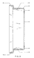
- FIG. 1 is a plan view of an air-operated diaphragm spring brake having an adjustable mounting means according to the invention
- FIG. 2 is a cross-sectional view of the air-operated diaphragm spring brake taken along lines 2-2 of FIG. 1;
- FIG. 3 is a cross-sectional view of the service brake housing used in the invention prior to being mounted to the adapter housing;
- FIG. 4 is a plan view of the central plate assembly according the invention.
- FIG. 5 is a cross-sectional view of the central plate assembly taken along lines 5-5 of FIG. 4.
- the brake 10 comprises a service brake 12 mounted in tandem to a spring brake 14.
- a brake mounting means 16 is disposed at the service brake 12.
- An actuator means 18 projects from the service brake and is adapted to connect to and operate a conventional brake shoe and drum (not shown) in conventional fashion.
- the service brake 12 comprises a cup-shaped service housing 20, and the spring brake 14 similarly comprises a cup-shaped spring housing 22.
- the service housing 20 and the spring housing 22 are each joined to a double cup-shaped service/spring adapter housing 24 by means of integrally formed seals 26, 28, respectively.
- the housing 20, 22 may also be joined to the adapter 24 by separate clamp bands when an integral seal is not used.
- the adapter housing 24 is provided with two pneumatic ports for delivery and exhaust of compressed air to the brake 10.
- the service port 30 directs air to the service brake 12, and the emergency port 32 directs air to and from the spring brake 14.
- a receptacle 34 is provided in the adapter housing 24 to receive and secure a release tool 35, the use of which is well known to manually disengage or render the spring brake inoperable.
- apertures 36 are provided on both the service housing 20 and the spring housing 22 for maintaining certain portions of the service brake 12 and spring brake 14, respectively, with ambient air pressure.
- a brake push rod 40 projects from the end of the service brake and is adapted for reciprocal movement to the left and right as illustrated in FIGS. 1 and 2.
- the push rod 40 carries a clevis 42 at an outer end thereof for connection to and operation of brake shoes and drums in conventional fashion.
- the service/spring adapter housing 24 forms a divider wall 50 between the service brake 12 and the spring brake 14.
- the housing 24 has a central opening 52 in the wall 50 with one or more O-rings 54 positioned therein.
- An indentation or annular depression 56 is formed around the opening 52.
- An elastomeric diaphragm 58 (known as the spring diaphragm) is suspended within the spring brake chamber 14' defined by the spring housing 22 and the adapter housing 24. The diaphragm 58 is compressed at the peripheral edge thereof between the adapter housing 24 and the spring housing 20 by means of the formed seal 26.
- An adapter push rod 60 is mounted within the spring brake chamber 14' and has a reaction plate 62 attached to one end and a pressure plate 64 attached to the other end thereof. The adapter push rod 60 extends through the opening 52 in sealing engagement with the O-rings 54. The reaction plate 62 seats within the annular depression 56 of the divider wall 50.
- a compression spring 66 is mounted within the spring brake chamber 14' between the divider wall 50 and the pressure plate 64 to urge the adapter push rod 60 into an inoperative position as illustrated in FIG. 2.
- the spring housing 20 has formed in a central portion thereof a cup portion 70 which defines a central opening 72.
- a receptacle plate 74 may have a conical portion 76 with an outer surface which complements the cup portion 72 and further has a pressure plate 78 at an inner portion thereof which bears against the diaphragm 58.
- a strong force compression spring 80 is positioned between the pressure plate 78 and the spring housing 20 to urge the adapter push rod 60 and the push rod 40 to an operative position.
- air pressure within the spring brake chamber 14' combined with the biasing force of compression spring 66 overcomes the force of the compression spring 80 to maintain the latter in a retracted position as illustrated in FIG. 2.
- the release tool 35 may be provided within the central opening 72 of the cone receptacle 70 to mechanically draw the receptacle plate 74 back into the fully retracted position illustrated in FIG. 2 in the event of an air pressure failure within the spring brake chamber 14', or if there is a need to cage the compression spring 80 in order to dismantle the brake or otherwise render the spring brake 14 inoperative.
- the service brake housing 22 comprises two parts, a generally cylindrical housing portion 82 and a central plate assembly 84.
- the cylindrical housing portion 82 has an outwardly directed annular flange 86 on one end and an inwardly directed annular flange 88 on another end.
- the outwardly directed flange 86 is adapted to form over a flange on the adapter housing 24 by swaging to form the seal 28.
- the seal 28 can be formed by outwardly directed flange 86', the service diaphragm clamp and the adapter housing flange being clamped together with a clamp band (not shown).
- the inwardly directed flange 88 defines a center opening 90.
- the housing portion 82 and the adapter housing 24 at least partially define a service brake chamber 12'.
- the central plate 84 has an annular shoulder 92 at the periphery thereof and an aperture 94 centrally located and extending through the plate 84.
- the housing portion 82 and the plate 84 are formed of steel to provide strength and to facilitate forming the seal 28.
- Mounting studs 96 are secured as by welding or by interference press fit knurls to the central plate 84 adjacent the annular shoulder 92. Each stud 96 has a head 98 and a threaded end 100. A steel stiffener 102 is secured to the plate as by welding or by press fit of the stud 96 to provide additional strength for the mounting studs 96. The threaded end 100 of each mounting stud 96 projects through a stiffener 102 and the central plate 84 so that the head 98 may be secured to the stiffener 102.
- the central plate 84 is disposed within the central opening 90 of the housing portion 82 so that the annular shoulder 92 mounts on the inwardly directed annular flange 88.
- the service brake push rod 40 is mounted in the service brake chamber 12' for reciprocation within the opening 94 of the central plate 84, and carries a pressure plate 104 at an inner end thereof.
- a first indicium 106 is integral with push rod 40 near the pressure plate 104 and so positioned on the push rod that it will begin to emerge from the opening 94 when the push rod 40 has approximately one-half inch of stroke remaining as it moves to an operative position in a manner described hereinafter.
- a second indicium 108 may likewise be integral with push rod 40 and located intermediate the first indicium 106 and the clevis 42.
- a compression spring 110 extends between the central plate 84 and the pressure plate 104. The spring 110 thus urges the pressure plate 104 and the service brake push rod 40 to the fully retracted position as viewed in FIG. 2. The fully retracted position may be defined as the inoperative position in which the brakes are released.
- the spring 110 also urges the central plate 84 outwardly to retain the shoulder 92 in abutment with the inwardly directed flange 88. However, the central plate 84 remains free to rotate with respect to the housing portion 82 so that the mounting studs 96 can therefore rotate about a central axis with respect to the adapter housing 24.
- a second elastomeric diaphragm 112 (also known as the service brake diaphragm) is mounted within the service brake chamber 12' and is clamped between the housing portion 82 and the adapter housing 24 within the formed seal 28 or by means of a clamping band.
- the spring biased pressure plate 104 forces the diaphragm 112 against the divider wall 50 of the adapter housing 24 to the inoperative position as shown in FIG. 2.
- the pressure in the spring brake chamber 14' will be decreased so that the springs 66, 110 would no longer be able to overcome the force of the much larger and stronger compression spring 80.
- the pressure plate 78 forces the spring diaphragm 58, and thus the adapter push rod 60 in a direction along a longitudinal axis of the push rod 60, thereby also forcing the push rod 40 to an operative position applying the braking pressure to the brakes.
- the brake 10 is mounted to a vehicle by securing the mounting studs 96 to a mounting support or bracket (not shown) with nuts 112 and lock washers 114.
- a mounting support or bracket not shown
- the entire brake 10 can be rotated generally about a longitudinal axis to align the pneumatic ports 30, 32 to a preselected position because the central plate 84 to which the mounting studs 96 are rigidly secured, is free to rotate with respect to the service brake housing 82.
- the present invention permits rotation of the brake during installation to align the ports to meet the air supply lines. With this structure, then, a single brake can be provided which is adapted to fit a number of different vehicles, regardless of the configuration of air conduits directed to the brake.
Landscapes
- Engineering & Computer Science (AREA)
- Transportation (AREA)
- Mechanical Engineering (AREA)
- Braking Arrangements (AREA)
- Braking Systems And Boosters (AREA)
Applications Claiming Priority (2)
| Application Number | Priority Date | Filing Date | Title |
|---|---|---|---|
| US452698 | 1989-12-12 | ||
| US07/452,698 US5016523A (en) | 1989-12-18 | 1989-12-18 | Adjustable mounting apparatus for air-operated diaphragm brakes |
Publications (2)
| Publication Number | Publication Date |
|---|---|
| EP0433571A1 true EP0433571A1 (de) | 1991-06-26 |
| EP0433571B1 EP0433571B1 (de) | 1994-07-20 |
Family
ID=23797558
Family Applications (1)
| Application Number | Title | Priority Date | Filing Date |
|---|---|---|---|
| EP90118034A Expired - Lifetime EP0433571B1 (de) | 1989-12-18 | 1990-09-19 | Einstellbare Montagevorrichtung für Druckluftbremsen |
Country Status (6)
| Country | Link |
|---|---|
| US (1) | US5016523A (de) |
| EP (1) | EP0433571B1 (de) |
| JP (1) | JPH03189261A (de) |
| AU (1) | AU623798B2 (de) |
| CA (1) | CA2022589A1 (de) |
| DE (1) | DE69010867T2 (de) |
Cited By (2)
| Publication number | Priority date | Publication date | Assignee | Title |
|---|---|---|---|---|
| EP1136337A1 (de) * | 2000-02-28 | 2001-09-26 | KNORR-BREMSE SYSTEME FÜR NUTZFAHRZEUGE GmbH | Kombinierter Betriebsbrems- und Federspeicherbremszylinder |
| EP1407172A1 (de) * | 2001-04-09 | 2004-04-14 | Haldex Brake Corporation | Radial abgedichtete druckluftbremskammer |
Families Citing this family (24)
| Publication number | Priority date | Publication date | Assignee | Title |
|---|---|---|---|---|
| US6029447A (en) * | 1995-02-21 | 2000-02-29 | Stojic; Steven M. | Spring brake actuator with filtered vent openings |
| US5623862A (en) * | 1995-08-17 | 1997-04-29 | Midland Brake, Inc. | Long stroke spring brake actuator |
| US5957032A (en) * | 1995-09-07 | 1999-09-28 | Neway Anchorlok International, Inc. | Air-operated brake actuator mounting |
| US5787794A (en) * | 1997-06-17 | 1998-08-04 | Indian Head Industries, Inc. | Mounting bolt for brake actuator |
| US6318240B1 (en) * | 1998-01-29 | 2001-11-20 | Indian Head Industries, Inc. | Brake actuator |
| US6148614A (en) * | 1998-06-12 | 2000-11-21 | Automotive Products (Usa), Inc. | Damper with integral bracket |
| US6314861B1 (en) * | 1999-06-18 | 2001-11-13 | Tse Brakes, Inc. | High output spring brake actuator |
| US6378414B1 (en) | 1999-06-28 | 2002-04-30 | Tse Brakes, Inc. | Removable filter cap for spring brake actuator |
| US6389954B1 (en) | 1999-11-19 | 2002-05-21 | Tse Brakes, Inc. | Removable filter plug for spring brake actuator |
| US6352137B1 (en) | 2000-03-22 | 2002-03-05 | Indian Head Industries, Inc. | Brake monitoring system |
| US6360649B1 (en) | 2000-04-26 | 2002-03-26 | Indian Head Industries, Inc. | Spring brake actuator |
| US8978841B2 (en) * | 2005-07-06 | 2015-03-17 | Wabtec Holding Corp | Universal brake assembly |
| DE112008003309T5 (de) * | 2007-12-03 | 2010-10-07 | Cts Corp., Elkhart | Linearer Positionssensor |
| DE112009003688B4 (de) * | 2008-11-26 | 2013-09-19 | Cts Corporation | Linearpositionssensor mit Drehblockiervorrichtung |
| US8443714B2 (en) * | 2009-12-08 | 2013-05-21 | Haldex Brake Corporation | Vibration/shock resistant stud housing |
| DE112010004761T5 (de) * | 2009-12-09 | 2012-11-29 | Cts Corporation | Antriebs- und Sensoranordnung |
| US9435630B2 (en) | 2010-12-08 | 2016-09-06 | Cts Corporation | Actuator and linear position sensor assembly |
| US9050958B2 (en) * | 2012-06-11 | 2015-06-09 | Tse Brakes, Inc. | Pneumatic brake actuator chamber with rotationally positionable housing |
| DE102013110639B4 (de) * | 2013-09-26 | 2020-08-06 | Knorr-Bremse Systeme für Nutzfahrzeuge GmbH | Verfahren zur Herstellung einer formschlüssigen Verbindung zwischen wenigstens einem aus einem verformbaren Material bestehenden Gehäuse eines Betriebsbremszylinder eines kombinierten Betriebsbrems- und Federspeicherbremszylinders |
| EP3287818B1 (de) | 2016-08-23 | 2020-11-11 | Corporation de L'Ecole Polytechnique de Montreal | Ophthalmische linse mit erhöhter widerstandsfähigkeit gegen warme und feuchte umgebungen |
| EP3306354B1 (de) | 2016-10-07 | 2021-12-22 | Corporation de L'Ecole Polytechnique de Montreal | Artikel mit einer nanolaminatbeschichtung |
| US10663025B2 (en) | 2018-07-31 | 2020-05-26 | Bendix Spicer Foundation Brake Llc | Bushing assembly for a spring brake actuator of a vehicle air braking system |
| US10767715B2 (en) | 2018-10-11 | 2020-09-08 | Bendix Spicer Foundation Brake Llc | Pivotable actuator mounting device |
| EP4086127A1 (de) * | 2021-05-06 | 2022-11-09 | ZF CV Systems Europe BV | Federspeicherbremszylinder |
Citations (3)
| Publication number | Priority date | Publication date | Assignee | Title |
|---|---|---|---|---|
| DE1188455B (de) * | 1963-07-11 | 1965-03-04 | Bergische Achsen Kotz Soehne | Befestigungsvorrichtung fuer Bremszylinder am Achskoerper von Fahrzeugen, insbesondere Anhaengerfahrzeugen |
| GB2071212A (en) * | 1980-02-23 | 1981-09-16 | Bergische Achsen Kotz Soehne | A device for mounting brake cylinders on axle beams of vehicles |
| EP0219613A1 (de) * | 1985-10-16 | 1987-04-29 | WABCO Westinghouse Fahrzeugbremsen GmbH | Federspeicherzylinder, insbesondere druckmittelbetätigter Federspeicherbremszylinder für Strassenfahrzeuge |
Family Cites Families (17)
| Publication number | Priority date | Publication date | Assignee | Title |
|---|---|---|---|---|
| US3331291A (en) * | 1965-07-15 | 1967-07-18 | Royal Industries | Emergency brake actuator |
| US3439585A (en) * | 1966-09-12 | 1969-04-22 | Dan B Herrera | Air brake and operator therefor |
| US3402792A (en) * | 1967-01-03 | 1968-09-24 | Neway Equipment Co | Brake actuating apparatus |
| US3613515A (en) * | 1969-03-10 | 1971-10-19 | Certain Teed Prod Corp | Brake actuator |
| US3630093A (en) * | 1970-01-16 | 1971-12-28 | Bendix Westinghouse Automotive | Spring brake release means |
| US3730056A (en) * | 1971-06-14 | 1973-05-01 | Certain Teed St Gobain | Double diaphragm brake operator improvements |
| US3811365A (en) * | 1971-09-13 | 1974-05-21 | Indian Head Inc | Brake mechanism |
| GB1408287A (en) * | 1972-11-28 | 1975-10-01 | Girling Ltd | Vehicle wheel brake actuators |
| US3943829A (en) * | 1972-12-19 | 1976-03-16 | Girling Limited | Vehicle wheel brake actuators |
| GB1440511A (en) * | 1973-03-27 | 1976-06-23 | Bendix Westinghouse Ltd | Brake actuators |
| US3926094A (en) * | 1973-07-02 | 1975-12-16 | Midland Ross Corp | Air operated spring brake |
| US4160472A (en) * | 1977-07-25 | 1979-07-10 | Arnold Industries, Inc. | Apparatus for splitting wood |
| US4259895A (en) * | 1979-06-11 | 1981-04-07 | Owens Roland G | Vacuum motor |
| US4263840A (en) * | 1979-10-29 | 1981-04-28 | Stratobrake Corporation | Safety brake mechanism |
| US4480530A (en) * | 1982-06-28 | 1984-11-06 | Aeroquip Corporation | Braking actuator |
| US4565120A (en) * | 1985-03-20 | 1986-01-21 | Aeroquip Corporation | Safety restraint for brake actuators |
| US4793449A (en) * | 1987-10-28 | 1988-12-27 | Thrall Car Manufacturing Company | Railraod truck braking system |
-
1989
- 1989-12-18 US US07/452,698 patent/US5016523A/en not_active Expired - Fee Related
-
1990
- 1990-08-02 CA CA002022589A patent/CA2022589A1/en not_active Abandoned
- 1990-08-13 AU AU60913/90A patent/AU623798B2/en not_active Ceased
- 1990-09-08 JP JP2238825A patent/JPH03189261A/ja active Pending
- 1990-09-19 EP EP90118034A patent/EP0433571B1/de not_active Expired - Lifetime
- 1990-09-19 DE DE69010867T patent/DE69010867T2/de not_active Expired - Fee Related
Patent Citations (3)
| Publication number | Priority date | Publication date | Assignee | Title |
|---|---|---|---|---|
| DE1188455B (de) * | 1963-07-11 | 1965-03-04 | Bergische Achsen Kotz Soehne | Befestigungsvorrichtung fuer Bremszylinder am Achskoerper von Fahrzeugen, insbesondere Anhaengerfahrzeugen |
| GB2071212A (en) * | 1980-02-23 | 1981-09-16 | Bergische Achsen Kotz Soehne | A device for mounting brake cylinders on axle beams of vehicles |
| EP0219613A1 (de) * | 1985-10-16 | 1987-04-29 | WABCO Westinghouse Fahrzeugbremsen GmbH | Federspeicherzylinder, insbesondere druckmittelbetätigter Federspeicherbremszylinder für Strassenfahrzeuge |
Cited By (3)
| Publication number | Priority date | Publication date | Assignee | Title |
|---|---|---|---|---|
| EP1136337A1 (de) * | 2000-02-28 | 2001-09-26 | KNORR-BREMSE SYSTEME FÜR NUTZFAHRZEUGE GmbH | Kombinierter Betriebsbrems- und Federspeicherbremszylinder |
| EP1407172A1 (de) * | 2001-04-09 | 2004-04-14 | Haldex Brake Corporation | Radial abgedichtete druckluftbremskammer |
| EP1407172A4 (de) * | 2001-04-09 | 2004-09-01 | Haldex Brake Corp | Radial abgedichtete druckluftbremskammer |
Also Published As
| Publication number | Publication date |
|---|---|
| JPH03189261A (ja) | 1991-08-19 |
| DE69010867D1 (de) | 1994-08-25 |
| US5016523A (en) | 1991-05-21 |
| EP0433571B1 (de) | 1994-07-20 |
| AU6091390A (en) | 1991-06-20 |
| DE69010867T2 (de) | 1995-03-02 |
| AU623798B2 (en) | 1992-05-21 |
| CA2022589A1 (en) | 1991-06-19 |
Similar Documents
| Publication | Publication Date | Title |
|---|---|---|
| US5016523A (en) | Adjustable mounting apparatus for air-operated diaphragm brakes | |
| CA1323586C (en) | Push-rod guide for air-operated diaphragm spring brakes | |
| EP0575830B1 (de) | Unbefugtem Manipulieren widerstehender Bremsbetätiger | |
| US10391997B2 (en) | Spring brake actuator with a caging bolt bearing joining a pressure plate and actuator tube | |
| KR100312584B1 (ko) | 유체로작동되는개량된압력판을갖춘스프링브레이크액추에이터 | |
| US5193432A (en) | Tamper-resistant brake actuator | |
| CA1323847C (en) | Stroke indicator for air operated diaphragm spring brakes | |
| US5771774A (en) | Spring brake actuator having plastic pressure plate assembly | |
| EP2760720B1 (de) | Feststellbremskolben für eine feststellbremskammer | |
| WO1994021892A1 (en) | Sealed bearing for fluid-operated brake actuator | |
| US6988442B2 (en) | Air brake diaphragms which resist pull-out | |
| US20220194341A1 (en) | Spring brake actuator for use in a commercial vehicle and commercial vehicle therewith | |
| US5957032A (en) | Air-operated brake actuator mounting | |
| AU709256B2 (en) | Spring brake actuator having plastic pressure plate assembly | |
| US5664478A (en) | Spring brake actuator with corrosion fuses | |
| CA2239052C (en) | Spring brake actuator with corrosion fuses | |
| WO1997010978A2 (en) | Air-operated brake actuator mounting |
Legal Events
| Date | Code | Title | Description |
|---|---|---|---|
| PUAI | Public reference made under article 153(3) epc to a published international application that has entered the european phase |
Free format text: ORIGINAL CODE: 0009012 |
|
| AK | Designated contracting states |
Kind code of ref document: A1 Designated state(s): AT BE CH DE DK ES FR GB GR IT LI LU NL SE |
|
| RBV | Designated contracting states (corrected) |
Designated state(s): DE FR GB |
|
| 17P | Request for examination filed |
Effective date: 19911217 |
|
| 17Q | First examination report despatched |
Effective date: 19930120 |
|
| GRAA | (expected) grant |
Free format text: ORIGINAL CODE: 0009210 |
|
| AK | Designated contracting states |
Kind code of ref document: B1 Designated state(s): DE FR GB |
|
| REF | Corresponds to: |
Ref document number: 69010867 Country of ref document: DE Date of ref document: 19940825 |
|
| ET | Fr: translation filed | ||
| PLBE | No opposition filed within time limit |
Free format text: ORIGINAL CODE: 0009261 |
|
| STAA | Information on the status of an ep patent application or granted ep patent |
Free format text: STATUS: NO OPPOSITION FILED WITHIN TIME LIMIT |
|
| 26N | No opposition filed | ||
| REG | Reference to a national code |
Ref country code: GB Ref legal event code: 732E |
|
| REG | Reference to a national code |
Ref country code: FR Ref legal event code: TP |
|
| PGFP | Annual fee paid to national office [announced via postgrant information from national office to epo] |
Ref country code: GB Payment date: 19980915 Year of fee payment: 9 |
|
| PGFP | Annual fee paid to national office [announced via postgrant information from national office to epo] |
Ref country code: FR Payment date: 19980928 Year of fee payment: 9 |
|
| PGFP | Annual fee paid to national office [announced via postgrant information from national office to epo] |
Ref country code: DE Payment date: 19981029 Year of fee payment: 9 |
|
| PG25 | Lapsed in a contracting state [announced via postgrant information from national office to epo] |
Ref country code: GB Free format text: LAPSE BECAUSE OF NON-PAYMENT OF DUE FEES Effective date: 19990919 |
|
| GBPC | Gb: european patent ceased through non-payment of renewal fee |
Effective date: 19990919 |
|
| PG25 | Lapsed in a contracting state [announced via postgrant information from national office to epo] |
Ref country code: FR Free format text: LAPSE BECAUSE OF NON-PAYMENT OF DUE FEES Effective date: 20000531 |
|
| PG25 | Lapsed in a contracting state [announced via postgrant information from national office to epo] |
Ref country code: DE Free format text: LAPSE BECAUSE OF NON-PAYMENT OF DUE FEES Effective date: 20000701 |
|
| REG | Reference to a national code |
Ref country code: FR Ref legal event code: ST |