EP0432550A2 - Device for testing containers for leaks - Google Patents
Device for testing containers for leaks Download PDFInfo
- Publication number
- EP0432550A2 EP0432550A2 EP90122446A EP90122446A EP0432550A2 EP 0432550 A2 EP0432550 A2 EP 0432550A2 EP 90122446 A EP90122446 A EP 90122446A EP 90122446 A EP90122446 A EP 90122446A EP 0432550 A2 EP0432550 A2 EP 0432550A2
- Authority
- EP
- European Patent Office
- Prior art keywords
- wall
- end wall
- test chamber
- plastic cap
- containers
- Prior art date
- Legal status (The legal status is an assumption and is not a legal conclusion. Google has not performed a legal analysis and makes no representation as to the accuracy of the status listed.)
- Withdrawn
Links
Images

Classifications
-
- G—PHYSICS
- G01—MEASURING; TESTING
- G01M—TESTING STATIC OR DYNAMIC BALANCE OF MACHINES OR STRUCTURES; TESTING OF STRUCTURES OR APPARATUS, NOT OTHERWISE PROVIDED FOR
- G01M3/00—Investigating fluid-tightness of structures
- G01M3/02—Investigating fluid-tightness of structures by using fluid or vacuum
- G01M3/26—Investigating fluid-tightness of structures by using fluid or vacuum by measuring rate of loss or gain of fluid, e.g. by pressure-responsive devices, by flow detectors
- G01M3/32—Investigating fluid-tightness of structures by using fluid or vacuum by measuring rate of loss or gain of fluid, e.g. by pressure-responsive devices, by flow detectors for containers, e.g. radiators
- G01M3/3209—Details, e.g. container closure devices
-
- G—PHYSICS
- G01—MEASURING; TESTING
- G01M—TESTING STATIC OR DYNAMIC BALANCE OF MACHINES OR STRUCTURES; TESTING OF STRUCTURES OR APPARATUS, NOT OTHERWISE PROVIDED FOR
- G01M3/00—Investigating fluid-tightness of structures
- G01M3/02—Investigating fluid-tightness of structures by using fluid or vacuum
- G01M3/04—Investigating fluid-tightness of structures by using fluid or vacuum by detecting the presence of fluid at the leakage point
- G01M3/20—Investigating fluid-tightness of structures by using fluid or vacuum by detecting the presence of fluid at the leakage point using special tracer materials, e.g. dye, fluorescent material, radioactive material
- G01M3/22—Investigating fluid-tightness of structures by using fluid or vacuum by detecting the presence of fluid at the leakage point using special tracer materials, e.g. dye, fluorescent material, radioactive material for pipes, cables or tubes; for pipe joints or seals; for valves; for welds; for containers, e.g. radiators
- G01M3/226—Investigating fluid-tightness of structures by using fluid or vacuum by detecting the presence of fluid at the leakage point using special tracer materials, e.g. dye, fluorescent material, radioactive material for pipes, cables or tubes; for pipe joints or seals; for valves; for welds; for containers, e.g. radiators for containers, e.g. radiators
- G01M3/227—Investigating fluid-tightness of structures by using fluid or vacuum by detecting the presence of fluid at the leakage point using special tracer materials, e.g. dye, fluorescent material, radioactive material for pipes, cables or tubes; for pipe joints or seals; for valves; for welds; for containers, e.g. radiators for containers, e.g. radiators for flexible or elastic containers
-
- G—PHYSICS
- G01—MEASURING; TESTING
- G01M—TESTING STATIC OR DYNAMIC BALANCE OF MACHINES OR STRUCTURES; TESTING OF STRUCTURES OR APPARATUS, NOT OTHERWISE PROVIDED FOR
- G01M3/00—Investigating fluid-tightness of structures
- G01M3/02—Investigating fluid-tightness of structures by using fluid or vacuum
- G01M3/26—Investigating fluid-tightness of structures by using fluid or vacuum by measuring rate of loss or gain of fluid, e.g. by pressure-responsive devices, by flow detectors
- G01M3/32—Investigating fluid-tightness of structures by using fluid or vacuum by measuring rate of loss or gain of fluid, e.g. by pressure-responsive devices, by flow detectors for containers, e.g. radiators
- G01M3/3218—Investigating fluid-tightness of structures by using fluid or vacuum by measuring rate of loss or gain of fluid, e.g. by pressure-responsive devices, by flow detectors for containers, e.g. radiators for flexible or elastic containers
-
- G—PHYSICS
- G01—MEASURING; TESTING
- G01M—TESTING STATIC OR DYNAMIC BALANCE OF MACHINES OR STRUCTURES; TESTING OF STRUCTURES OR APPARATUS, NOT OTHERWISE PROVIDED FOR
- G01M3/00—Investigating fluid-tightness of structures
- G01M3/02—Investigating fluid-tightness of structures by using fluid or vacuum
- G01M3/26—Investigating fluid-tightness of structures by using fluid or vacuum by measuring rate of loss or gain of fluid, e.g. by pressure-responsive devices, by flow detectors
- G01M3/32—Investigating fluid-tightness of structures by using fluid or vacuum by measuring rate of loss or gain of fluid, e.g. by pressure-responsive devices, by flow detectors for containers, e.g. radiators
- G01M3/3281—Investigating fluid-tightness of structures by using fluid or vacuum by measuring rate of loss or gain of fluid, e.g. by pressure-responsive devices, by flow detectors for containers, e.g. radiators removably mounted in a test cell
- G01M3/329—Investigating fluid-tightness of structures by using fluid or vacuum by measuring rate of loss or gain of fluid, e.g. by pressure-responsive devices, by flow detectors for containers, e.g. radiators removably mounted in a test cell for verifying the internal pressure of closed containers
Definitions
- the invention relates to a device for testing the tightness of containers, in particular drums, which are provided with at least one substantially flat end wall, consisting of at least one test chamber for receiving the containers, devices with which the test chamber can be evacuated and from one each associated with the end wall of the container attached to the test chamber support device with which bulging of the end wall is prevented.
- test devices for this purpose, in which the barrels are inserted into a test chamber which can be subjected to a vacuum, after they have previously been partly filled with an inoculation gas which can be detected in a particularly simple and precise manner using known measuring methods.
- the negative pressure occurring in the test chamber causes the test gas to escape at leak points in the container, and a measuring device assigned to the test chamber can determine in this way whether the test specimen is sealed over its entire circumference or not.
- the invention is therefore based on the object of avoiding the difficulties of adjusting the supporting force in a device for testing the tightness of the type mentioned.
- the support device consists of an elastic wall on its side facing the end wall with projections for support thereon and on the rear side of a space in which the atmospheric pressure prevails, the wall is approximately parallel is arranged to the end wall and is held with its edges close to a part of the test chamber.
- the invention is based on the known perception that two opposing deformable walls, between which there is negative pressure, but on the back of which there is the same pressure, are also subjected to the same forces if they are designed to be elastic enough. Since the forces exerted by each wall then neutralize each other, a simple but effective support of end walls can be achieved in this way, which otherwise tend to bulge.
- the arrangement of the projections ensures that connection paths remain free over the entire surface of the elastic wall, which can also apply the negative pressure of the test chamber to the end face, even if the wall presses against the end face. The entire barrel surface can be tested for leaks in this way.
- claims 3 and 4 allow a particularly simple design for the testing of cylindrical barrels, the plastic bellows designed as a support device providing the possibility of a larger deformation path, so that in a very simple manner there is also an abutment on the end faces of barrels, which are set back behind a peripheral edge and can be used in a cylindrical test chamber with a circular cover, which is also arranged at a distance from the front edges of the barrel.
- the features of claims 5 and 6 have the advantage that the negative pressure occurring in the test chamber can spread in a very simple manner to the center of the plastic cap and not through areas of the plastic cap lying against the end face of the barrel from certain areas between the plastic cap and the front of the barrel is sealed. The front of the barrel can therefore also be checked for leaks.
- the features of claim 7 allow a simple and tight attachment of the plastic bellows cap.
- the features of claims 8 and 9 ensure a certain degree of rigidity in the mooring area and therefore also ensure that the counterforce is as uniform as possible against the bulging end wall and the features of claim 10 finally result in the event that in an unpredictable manner on the inside and outside the pressure prevailing in the test chamber changes somewhat, a mechanical support for the plastic cap, which in any case avoids excessive bulging of one end of the barrel.
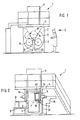
- a leak test machine (1) which consists of a frame (2) which is arranged in a stationary manner on the floor and which is approximately frame-shaped and is covered by a platform (3), the contours of which are shown in FIG. 3 are indicated by dash-dotted lines. Measuring devices and a vacuum pump device are arranged in a housing (4) on this platform in a manner not shown.
- a wheel star (5) is rotatably arranged in the frame (2) and is provided with three cylindrical drums (6), each offset by 120 ° to one another, which are arranged on the wheel star (5) so as to be rotatable about a common axis (7) are.
- a common axis (7) In the position (6 and 6 ') (Fig. 1) two of the cylindrical drums (6) are arranged in a common horizontal plane, which is selected such that barrels (9, 9') lying on a loading ramp (8) are also so are high that they can be easily inserted into and out of the cylindrical chambers can be removed again.
- Fig. 1 In the position (6 and 6 ') (Fig. 1) two of the cylindrical drums (6) are arranged in a common horizontal plane, which is selected such that barrels (9, 9') lying on a loading ramp (8) are also so are high that they can be easily inserted into and out of the cylindrical chambers can be removed again.
- the barrel (9) is inserted into the cylindrical chamber in the position (6 ') by a loading device, not explained in detail, for example with the aid of a pneumatic cylinder, in the direction of arrow (10), while at the same time the barrel (9 ') is moved out of the chamber (6) opposite the chamber (6') in the same horizontal plane in the sense of the arrow (11) with the aid of a pneumatic slide, also not shown.
- the third cylindrical drum is in position (6'') and is there to be described on both, or at least on one side closed, pressurized and sensed with the help of measuring instruments, not shown, whether there is test gas in the cylindrical drum.
- the wheel star (5) rotates in the frame (2) in the direction of the arrows (12), so that the cylindrical drum (6 '') in the test position is now in the position shown in FIG. 1 (6) arrives where the test object is unloaded.
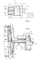
- the cover (14) that can be seen in FIG. 2 is provided with a peripheral edge (16) and with a seal (17) with which it is tightly attached to the flange (15) of the drum ( 6) can create when it has reached position (6 '').
- the cover (14) which is approximately circular, is fixedly arranged on an axis (18) which, via a pneumatic or hydraulic cylinder (19), moves in the direction of its axis (20) from the closed position (18) the position (18 ') can be shifted in which the cover (14), in its position (14'), is lifted off the flange (15) of the drum (6).
- the axis (18) is arranged in a longitudinally displaceable manner in a bearing (20) of a bearing block (21) which is firmly connected to the frame (2), as indicated in FIG. 4.
- the hydraulic or pneumatic cylinder (19) is also firmly screwed to the bearing block (21).
- the intermediate piece (24), which is rotatable relative to the piston rod (22) with the aid of a handle (25), has the task of being able to completely uncouple the hydraulic cylinder (19) from the ring (23) in order to be able to assemble or To be able to carry out disassembly.
- this is not important in the present invention.
- a ring bead (27) of a bellows-like cap (28) made of elastic plastic is fastened to the cover (14) with the aid of a fastening ring (26) and tightly clamped between the ring (26) and the cover (24).
- the cap (28) consists of a bellows-like outer edge (29) which integrally merges into a circular wall (28a) which is approximately parallel to the surface of the ring (26) and to the cover (14) and thus also runs parallel to the plane in which the end sealing flange (15) of the barrel (6) runs.
- a drum (9) is located within the drum (6) in position (6 '') of FIG. 1, which is indicated by dash-dotted lines.
- the essentially flat end wall (9a) of the barrel (9) lies in the middle in the closed position of the drum (6) (position 6 ′′) shown in FIG. 4 on the circular wall (28a).
- the wall (28a) also presses on nozzles (32) which protrude from the end wall region (9a) and which, for example, can be the filling nozzles of the barrel. In the open position of the cover (14 ') there is sufficient axial distance between the end edge (15) of the drum (6) and the wall (28a) of the support cap (28).
- the support cap (28) is provided in the middle with a cylindrical pin (33) projecting towards the bead (27), which protrudes somewhat beyond the plane of the bead (27) to the rear .
- This pin (33) serves as mechanical securing of the position of the support cap (28) on the cover (14).
- FIG. 5 and 6 also show that the inside of the drum (6) facing the side of the wall (28a) is provided with a plurality of individual knobs (34) protruding from the wall surface, which are semicircular in the exemplary embodiment and therefore the Have the shape of spherical sections.
- This design of the outside of the cap (28) ensures that the wall (28a) at no point can be so close to a counter wall, for example to the front wall (9a) of a barrel, that a pressure equalization between the outer areas of the membrane like wall (28a) and its interior is no longer possible.
- the negative pressure applied in position (6 '') inside the closed drum (6) ensures that the membrane-like wall (28a) the support cap (28) is pressed to the left against the end wall (9a) of the barrel (9) due to the pressure difference occurring in the space (30) and in the interior (35) of the drum (6).
- a similar cover cap (28) presses, which sits on the second mirror-symmetrically arranged cover (14), so that the position of the barrel within the drum (6) is secured during the leak test.
- the front wall (9a) of the barrel (9) tends to be deformed to the right with the same force as the membrane-like wall (28a) is deformed to the left.
- the hood-like support (28) is therefore suitable for avoiding excessive bulging of the end wall (9a) without the need for separate, complex devices for setting a counterforce. Nevertheless, the entire surface of the drum can be properly checked for leaks.
Landscapes
- Physics & Mathematics (AREA)
- General Physics & Mathematics (AREA)
- Examining Or Testing Airtightness (AREA)
Abstract
Description
Die Erfindung betrifft eine Vorrichtung zur Prüfung der Dichtheit von Behältern, insbesondere von Fässern, die mit mindestens einer im wesentlichen eben verlaufenden Stirnwand versehen sind, bestehend aus mindestens einer Prüfkammer zur Aufnahme der Behälter, aus Einrichtungen, mit denen die Prüfkammer evakuierbar ist und aus einer jeweils der Stirnwand des Behälters zugeordneten an der Prüfkammer angebrachten Abstützeinrichtung, mit der ein Ausbeulen der Stirnwand verhindert wird.The invention relates to a device for testing the tightness of containers, in particular drums, which are provided with at least one substantially flat end wall, consisting of at least one test chamber for receiving the containers, devices with which the test chamber can be evacuated and from one each associated with the end wall of the container attached to the test chamber support device with which bulging of the end wall is prevented.
Es gibt eine ganze Reihe von Behältern, insbesondere in Faßform, bei denen es auf die Dichtheit ankommt. Dies gilt insbesondere für die Aufnahme von Flüssigkeiten, welche schädliche Gase entwickeln, die nicht aus den Fässern austreten dürfen.There is a whole range of containers, especially in barrel form, where tightness is important. This applies in particular to the absorption of liquids that develop harmful gases that must not escape from the barrels.
Es ist bekannt, hierfür Prüfungsvorrichtungen vorzusehen, bei denen die Fässer in eine mit Vakuum beaufschlagbare Prüfkammer eingesetzt werden, nachdem sie vorher mit einem Impfgas zum Teil gefüllt wurden, das sich mit bekannten Meßmethoden auf besonders einfache und genaue Weise nachweisen läßt. Der in der Prüfkammer auftretende Unterdruck bewirkt den Austritt des Testgases an Leckstellen des Behälters und eine der Prüfkammer zugeordnete Meßeinrichtung kann auf diese Weise feststellen, ob der Prüfling über seinen gesamten Umfang dicht ist oder nicht.It is known to provide test devices for this purpose, in which the barrels are inserted into a test chamber which can be subjected to a vacuum, after they have previously been partly filled with an inoculation gas which can be detected in a particularly simple and precise manner using known measuring methods. The negative pressure occurring in the test chamber causes the test gas to escape at leak points in the container, and a measuring device assigned to the test chamber can determine in this way whether the test specimen is sealed over its entire circumference or not.
Da die zu prüfenden Behälter, insbesondere Fässer, wie angedeutet, vor dem Verschließen zwar mit einem Testgas geimpft, im Inneren aber im übrigen unter Atmosphärendruck stehen, bewirkt das Anlegen von Unterdruck in der Prüfkammer, daß innerhalb der Behälter bzw. der Fässer ein relativer Überdruck entsteht, der dazu führt, die Behälterwände nach außen zu beulen. Dies kann insbesondere an den ebenen Stirnwänden von Fässern oder ähnlich geformter Behälter zu einer irreversiblen, nicht zulässigen Verformung der Stirnwand, oder auch zum Bersten des Behälters führen. Um dies zu vermeiden, ist es bekannt, an diese ausbeulgefährdeten Stirnflächen eine an der Prüfkammer angeordnete Abstützeinrichtung anzulegen, die beispielsweise mit einem einstellbaren Federdruck gegen die Stirnwand drückt. Es ist schwierig und bedarf der jeweiligen Anpassung an verschiedene Behälter, diese Abstützkraft so einzustellen, daß sie den gewünschten Abstützeffekt bringt. Prüfvorrichtungen der bekannten Art sind daher relativ aufwendig.Since the containers to be tested, in particular drums, as indicated, are inoculated with a test gas before being sealed, but inside they are otherwise under atmospheric pressure, the application of negative pressure in the test chamber causes a relative overpressure within the container or the drums arises, which leads to the container walls bulging outwards. This can lead to an irreversible, inadmissible deformation of the end wall or even to the bursting of the container, particularly on the flat end walls of drums or similarly shaped containers. In order to avoid this, it is known to place a support device arranged on the test chamber on these end faces which are at risk of bulging and which, for example, presses against the end wall with an adjustable spring pressure. It is difficult and requires the respective adaptation to different containers to adjust this support force so that it brings the desired support effect. Test devices of the known type are therefore relatively complex.
Aus der GB-PS 840 294 ist es bei einer Einrichtung zur Leckprüfung von Behältern zwar schon bekannt, zwischen einer festen Prüfkammerbehälterwand und dem zu prüfenden Behälter eine elastische Hülle vorzusehen, die sich beim Auftreten einer Druckdifferenz zwischen ihrer Innen- und Außenseite allseitig dicht an die Wandungen des Behälters anlegt. Nur in den z.B. die Stirnwand eines Fasses umgebenden Saumbereichen und an bestimmten Stellen, an denen feste Einlagen in die Hülle eingebracht sind, die z.B. den Stellen einer Fasslängsnaht entsprechen können, entstehen Kanäle, die das Volumen der Prüfkammer bilden. Bei einer solchen Einrichtung werden zwar die Wände des zu prüfenden Behälters gegen Druckdifferenzen abgestützt und das geringere Volumen der Prüfkammer erlaubt auch eine schnellere und wirtschaftliche Prüfung. Es ist aber nicht möglich, die gesamte Oberfläche des Behälters auf diese Weise auf Dichtheit zu prüfen. Das ist aber die Aufgabe bei Vorrichtungen der eingangs genannten Art.From GB-PS 840 294 it is already known in a device for leak testing of containers to provide an elastic cover between a fixed test chamber container wall and the container to be tested, which is tight on all sides when a pressure difference occurs between its inside and outside Walls of the container creates. Channels, which form the volume of the test chamber, are only formed in the hem areas surrounding the front wall of a barrel and at certain points at which fixed inserts are inserted into the casing, which can correspond, for example, to the locations of a longitudinal barrel seam. With such a device, the walls of the container to be tested are supported against pressure differences and the smaller volume of the test chamber also enables a quicker and more economical test. However, it is not possible to check the entire surface of the container for leaks in this way. But that is the task with devices of the type mentioned.
Der Erfindung liegt daher die Aufgabe zugrunde, bei einer Vorrichtung zur Prüfung der Dichtheit der eingangs genannten Art die Schwierigkeiten der Einjustierung der Abstützkraft zu vermeiden.The invention is therefore based on the object of avoiding the difficulties of adjusting the supporting force in a device for testing the tightness of the type mentioned.
Gemäß der Erfindung wird dies dadurch erreicht, daß die Abstützeinrichtung aus einer elastischen, an ihrer der Stirnwand zugewandten Seite mit Vorsprüngen zur Abstützung an dieser versehenen und an ihrer Rückseite an einen Raum, in dem der Atmosphärendruck herrscht, angrenzenden Wand besteht, die in etwa parallel zu der Stirnwand angeordnet und mit ihren Rändern dicht an einem Teil der Prüfkammer gehalten ist. Durch diese Ausgestaltung wird auf die elastische Wand, deren Größe zweckmäßig an die der abzustützenden Stirnfläche angepaßt wird, durch den in der Prüfkammer entstehenden Unterdruck eine Kraft ausgeübt, die der Kraft der sich ausbeulenden Stirnwand in etwa mit gleicher Größe entgegenwirkt. Eine Einjustierung von Abstützkräften wird dadurch überflüssig. Die neue Einrichtung arbeitet auch unabhängig davon, wie niedrig der Unterdruck ist, der in der Prüfkammer herrscht.According to the invention, this is achieved in that the support device consists of an elastic wall on its side facing the end wall with projections for support thereon and on the rear side of a space in which the atmospheric pressure prevails, the wall is approximately parallel is arranged to the end wall and is held with its edges close to a part of the test chamber. By means of this configuration, a force is exerted on the elastic wall, the size of which is expediently adapted to that of the end face to be supported, by the negative pressure which arises in the test chamber, which counteracts the force of the bulging end wall with approximately the same size. An adjustment of support forces is therefore unnecessary. The new facility also works regardless of how low the vacuum in the test chamber.
Die Erfindung geht dabei von der an sich bekannten Erkenntnis aus, daß zwei sich gegenüberliegende verformbare Wände, zwischen denen ein Unterdruck herrscht, auf deren Rückseite aber jeweils der gleiche Druck vorliegt, auch mit den gleichen Kräften beaufschlagt werden, wenn sie elastisch genug ausgelegt sind. Da sich dann die von jeder Wand ausgeübten Kräfte gegenseitig neutralisieren, kann auf diese Weise eine einfache, aber wirksame Abstützung von Stirnwänden erreicht werden, die sonst zum Ausbeulen neigen. Durch die Anordnung der Vorsprünge wird dabei erreicht, daß über die gesamte Fläche der elastischen Wand Verbindungswege freibleiben, die den Unterdruck der Prüfkammer auch an der Stirnseite anliegen lassen, auch wenn sich die Wand an die Stirnseite andrückt. Die gesamte Fassoberfläche kann auf diese Weise auf Dichtheit getestet werden.The invention is based on the known perception that two opposing deformable walls, between which there is negative pressure, but on the back of which there is the same pressure, are also subjected to the same forces if they are designed to be elastic enough. Since the forces exerted by each wall then neutralize each other, a simple but effective support of end walls can be achieved in this way, which otherwise tend to bulge. The arrangement of the projections ensures that connection paths remain free over the entire surface of the elastic wall, which can also apply the negative pressure of the test chamber to the end face, even if the wall presses against the end face. The entire barrel surface can be tested for leaks in this way.
Vorteilhafte Weiterbildungen der Erfindung sind in den Unteransprüchen gekennzeichnet. Die Merkmale des Anspruches 3 und 4 ermöglichen eine besonders einfache Bauart für die Prüfung zylindrischer Fässer, wobei der als Abstützeinrichtung ausgebildete Kunststoffbalg die Möglichkeit eines größeren Verformungsweges zur Verfügung stellt, so daß in sehr einfacher Weise auch eine Anlage an den Stirnflächen von Fässern besteht, die hinter einem umlaufenden Rand zurückgesetzt sind und in einer zylindrischen Prüfkammer mit kreisrundem Abschlußdeckel eingesetzt werden können, der ebenfalls mit Abstand zu den stirnseitigen Rändern des Fasses angeordnet ist. Die Merkmale der Ansprüche 5 und 6 bringen den Vorteil mit sich, daß der in der Prüfkammer auftretende Unterdruck sich in sehr einfacher Weise bis in die Mitte der Kunststoffkappe ausbreiten kann und nicht durch an der Stirnseite des Fasses anliegende Bereiche der Kunststoffkappe von bestimmten Bereichen zwischen Kunststoffkappe und Stirnseite des Fasses abgedichtet ist. Auch die Stirnseite des Fasses kann daher sicher auf Dichtheit geprüft werden.Advantageous developments of the invention are characterized in the subclaims. The features of claims 3 and 4 allow a particularly simple design for the testing of cylindrical barrels, the plastic bellows designed as a support device providing the possibility of a larger deformation path, so that in a very simple manner there is also an abutment on the end faces of barrels, which are set back behind a peripheral edge and can be used in a cylindrical test chamber with a circular cover, which is also arranged at a distance from the front edges of the barrel. The features of
Die Merkmale des Anspruches 7 erlauben eine einfache und dichte Befestigung der Kunststoffbalgkappe. Die Merkmale der Ansprüche 8 und 9 gewährleisten eine gewisse Steifigkeit im Anlegebereich und sorgen daher auch für eine möglichst gleichmäßige Gegenkraft gegenüber der sich ausbeulenden Stirnwand und die Merkmale des Anspruches 10 schließlich bewirken für den Fall, daß sich in unvorhersehbarer Weise an den in- und außerhalb der Prüfkammer herrschenden Drücken etwas ändert, eine mechanische Abstützung für die Kunststoffkappe, die in jedem Fall ein übermäßiges Ausbeulen einer Faßstirnseite vermeidet.The features of
In der Zeichnung ist die Erfindung anhand eines Ausführungsbeispieles dargestellt, das im folgenden erläutert wird. Es zeigen:
- Fig. 1
- eine schematische Frontansicht einer erfindungsgemäß ausgebildeten Vorrichtung zum Prüfen der Dichtheit von Fässern,
- Fig. 2
- die teilweise aufgebrochene Seitenansicht der Vorrichtung der Fig. 1 in Richtung des Pfeiles II gesehen,
- Fig. 3
- die Draufsicht auf die Vorrichtung der Fig. 1 und 2,
- Fig. 4
- eine vergrößerte Teildarstellung des Abschlußbereiches der in der Testposition befindlichen Trommel der Vorrichtung gemäß der Erfindung,
- Fig. 5
- eine Frontansicht der balgartigen Kunststoffkappe in Fig. 4 in Richtung des Pfeiles V und
- Fig. 6
- die Darstellung des Schnittes längs der Linie VI-VI in Fig. 5.
- Fig. 1
- is a schematic front view of an inventive trained device for testing the tightness of drums,
- Fig. 2
- the partially broken side view of the device of FIG. 1 seen in the direction of arrow II,
- Fig. 3
- the top view of the device of FIGS. 1 and 2,
- Fig. 4
- 2 shows an enlarged partial view of the end region of the drum of the device according to the invention which is in the test position
- Fig. 5
- a front view of the bellows-like plastic cap in Fig. 4 in the direction of arrow V and
- Fig. 6
- the representation of the section along the line VI-VI in Fig. 5th
In den Fig. 1 bis 3 ist eine Lecktestprüfmaschine (1) gezeigt, die aus einem ortsfest auf dem Boden angeordneten Gestell (2) besteht, das etwa rahmenförmig ausgebildet ist und von einer Plattform (3) überdacht wird, deren Konturen in der Fig. 3 strichpunktiert angedeutet sind. Auf dieser Plattform sind in nicht näher dargestellter Weise Meßeinrichtungen und eine Vakuumpumpeneinrichtung in einem Gehäuse (4) angeordnet.1 to 3, a leak test machine (1) is shown which consists of a frame (2) which is arranged in a stationary manner on the floor and which is approximately frame-shaped and is covered by a platform (3), the contours of which are shown in FIG. 3 are indicated by dash-dotted lines. Measuring devices and a vacuum pump device are arranged in a housing (4) on this platform in a manner not shown.
In dem Gestell (2) ist drehbar ein Radstern (5) angeordnet, der mit drei, jeweils um 120° zueinander versetzt angeordneten zylindrischen Trommel (6) versehen ist, die an dem Radstern (5) um eine gemeinsame Achse (7) drehbar angeordnet sind. In der Position (6 und 6') (Fig. 1) sind zwei der zylindrischen Trommeln (6) in einer gemeinsamen Horizontalebene angeordnete, die so gewählt ist, daß auf einer Laderampe (8) liegende Fässer (9, 9') ebenfalls so hoch liegen, daß sie ohne Schwierigkeiten in die zylindrischen Kammern eingeschoben bzw. aus diesen wieder entnommen werden können. Wie Fig. 3 zeigt, wird dabei das Faß (9) durch eine nicht näher erläuterte Beladeeinrichtung, zum Beispiel mit Hilfe eines pneumatischen Zylinders, in Richtung des Pfeiles (10) in die zylindrische Kammer in der Position (6') eingeschoben, während gleichzeitig das Faß (9') im Sinn des Pfeiles (11) aus der der Kammer (6') in der gleichen Horizontalebene gegenüberliegenden Kammer (6) mit Hilfe eines ebenfalls nicht gezeigten pneumatischen Schiebers herausbewegt wird. Während dieses Be- und Entladevorganges, das an den zylindrischen Trommeln (6 und 6') stattfindet, befindet sich die dritte zylindrische Trommel in der Position (6''), wird dort in noch zu schildernder Weise an beiden, oder zumindest an einer Seite geschlossen, unter Unterdruck gesetzt und mit Hilfe nicht gezeigter Meßinstrumente abgefühlt, ob sich Testgas in der zylindrischen Trommel befindet. Ist dieser Testvorgang beendet, dreht sich der Radstern (5) in dem Gestell (2) im Sinn der Pfeile (12), so daß die in der Testposition befindliche zylindrische Trommel (6'') nun in die in der Fig. 1 bezeichnete Position (6) gelangt, wo der Prüfling entladen wird.A wheel star (5) is rotatably arranged in the frame (2) and is provided with three cylindrical drums (6), each offset by 120 ° to one another, which are arranged on the wheel star (5) so as to be rotatable about a common axis (7) are. In the position (6 and 6 ') (Fig. 1) two of the cylindrical drums (6) are arranged in a common horizontal plane, which is selected such that barrels (9, 9') lying on a loading ramp (8) are also so are high that they can be easily inserted into and out of the cylindrical chambers can be removed again. As shown in Fig. 3, the barrel (9) is inserted into the cylindrical chamber in the position (6 ') by a loading device, not explained in detail, for example with the aid of a pneumatic cylinder, in the direction of arrow (10), while at the same time the barrel (9 ') is moved out of the chamber (6) opposite the chamber (6') in the same horizontal plane in the sense of the arrow (11) with the aid of a pneumatic slide, also not shown. During this loading and unloading process, which takes place on the cylindrical drums (6 and 6 '), the third cylindrical drum is in position (6'') and is there to be described on both, or at least on one side closed, pressurized and sensed with the help of measuring instruments, not shown, whether there is test gas in the cylindrical drum. When this test is finished, the wheel star (5) rotates in the frame (2) in the direction of the arrows (12), so that the cylindrical drum (6 '') in the test position is now in the position shown in FIG. 1 (6) arrives where the test object is unloaded.
Um den Drehvorgang des Radsternes (5) zu ermöglichen und in den Positionen (6' und 6) das Be- und Entladen in einfacher Weise gestalten zu können, sind in dem Gestell (2) zwischen einem vorderen Träger (2a), der sich V-förmig zur Plattform (3) hin nach oben erweitert, und einer hinteren Wand (2b) des Gestelles zum einen die Lagerungen für die Achse (13) des Radsternes (5), zum anderen aber - jeweils an der vorderen bzw. hinteren Wand - Deckel (14) angeordnet, von denen einer in der Fig. 4 im einzelnen dargestellt ist und erläutert wird. Der vordere und der hintere Deckel (14) werden daher gegen die Stirnwand (15) der zylindrischen Trommel (6) gedrückt, sobald diese die obere Position (6'') erreicht hat und der Radstern (5) über einen nicht näher gezeigten Antrieb (36) zum Stillstand gekommen ist. Ist die Leckprüfung beendet, so werden beide Deckel (14) wieder axial von den Stirnseiten (15) der Trommel (6) entfernt und der Radstern (5) kann im Sinn der Pfeile (12) gedreht werden, bis die Trommeln die jeweils nächste Position erreicht haben.In order to enable the turning process of the wheel star (5) and to make loading and unloading in the positions (6 'and 6) simple, in the frame (2) between a front carrier (2a), which V -shaped to the platform (3) upwards, and a rear wall (2b) of the frame on the one hand the bearings for the axis (13) of the wheel spider (5), but on the other hand - in each case on the front or rear wall - Cover (14) arranged, one of which is shown in detail in FIG. 4 and explained. The front and the rear cover (14) are therefore pressed against the end wall (15) of the cylindrical drum (6) as soon as it has reached the upper position (6 '') and the wheel spider (5) via a drive (not shown) ( 36) has come to a standstill. When the leak test has ended, both covers (14) are axially removed from the end faces (15) of the drum (6) and the Wheel star (5) can be turned in the direction of arrows (12) until the drums have reached the next position.
Wie die Fig. 4 zeigt, ist der in der Fig. 2 zu erkennende Deckel (14) mit einem umlaufenden Rand (16) und mit einer Dichtung (17) versehen, mit der er sich dicht an dem Flansch (15) der Trommel (6) anlegen kann, wenn diese die Position (6'') erreicht hat. Der Deckel (14), der in etwa kreisförmig ausgebildet ist, ist zu diesem Zweck fest auf einer Achse (18) angeordnet, die über einen pneumatischen oder hydraulischen Zylinder (19) in Richtung ihrer Achse (20) aus der Schließposition (18) in die Position (18') verschoben werden kann, in der der Deckel (14), in seiner Lage (14'), von dem Flansch (15) der Trommel (6) abgehoben ist. Die Achse (18) ist längsverschiebbar in einem Lager (20) eines Lagerbockes (21) angeordnet, der fest mit dem Gestell (2) verbunden ist, wie in Fig. 4 angedeutet ist. Der hydraulische oder pneumatische Zylinder (19) ist ebenfalls fest mit dem Lagerbock (21) verschraubt. Seine Kolbenstange (22) dagegen greift über ein Zwischenstück (24) an einem fest mit der Achse (18) verbundenen Ring (23) an, so daß die Achse (18) aus der geschlossenen Stellung in die geöffnete Stellung (18') verschiebbar ist. Dem Zwischenstück (24), das verdrehbar gegenüber der Kolbenstange (22) mit Hilfe eines Handgriffes (25) ist, kommt dabei die Aufgabe zu, den hydraulischen Zylinder (19) vollständig von dem Ring (23) abkoppeln zu können, um Montage- oder Demontagevorgänge vornehmen zu können. Hierauf kommt es aber bei der vorliegenden Erfindung nicht an.As shown in FIG. 4, the cover (14) that can be seen in FIG. 2 is provided with a peripheral edge (16) and with a seal (17) with which it is tightly attached to the flange (15) of the drum ( 6) can create when it has reached position (6 ''). For this purpose, the cover (14), which is approximately circular, is fixedly arranged on an axis (18) which, via a pneumatic or hydraulic cylinder (19), moves in the direction of its axis (20) from the closed position (18) the position (18 ') can be shifted in which the cover (14), in its position (14'), is lifted off the flange (15) of the drum (6). The axis (18) is arranged in a longitudinally displaceable manner in a bearing (20) of a bearing block (21) which is firmly connected to the frame (2), as indicated in FIG. 4. The hydraulic or pneumatic cylinder (19) is also firmly screwed to the bearing block (21). Its piston rod (22), on the other hand, engages via an intermediate piece (24) on a ring (23) fixedly connected to the axle (18), so that the axle (18) can be moved from the closed position into the open position (18 ') . The intermediate piece (24), which is rotatable relative to the piston rod (22) with the aid of a handle (25), has the task of being able to completely uncouple the hydraulic cylinder (19) from the ring (23) in order to be able to assemble or To be able to carry out disassembly. However, this is not important in the present invention.
An dem Deckel (14) ist mit Hilfe eines Befestigungsringes (26) ein Ringwulst (27) einer aus elastischem Kunststoff bestehenden balgartigen Kappe (28) befestigt und zwischen dem Ring (26) und dem Deckel (24) dicht eingeklemmt. Die Kappe (28) besteht aus einem balgartig wirkenden Außenrand (29), der einstückig in eine kreisförmige Wand (28a) übergeht, die etwa parallel zu der Fläche des Ringes (26) und zum Deckel (14) und damit auch parallel zu der Ebene verläuft, in der der stirnseitige Dichtflansch (15) der Tonne (6) verläuft. Auf der von dem Inneren der Tonne (6) abgewandten Teil der Wand (28a) schließt ein von dieser Wand und von dem Deckel (14) begrenzter Raum (30) an, der, wie durch die schematisch angedeuteten Öffnungen (31) zum Ausdruck kommen soll, mit der Atmosphäre außerhalb der abgeschlossenen Trommel (6) in Verbindung steht. Innerhalb der Trommel (6) befindet sich in der Position (6'') der Fig. 1 ein Faß (9), das strichpunktiert angedeutet ist. Die im wesentlichen ebene Stirnwand (9a) des Fasses (9) liegt in der in Fig. 4 oben gezeigten geschlossenen Stellung der Trommel (6) (Position 6'') in der Mitte an der kreisförmigen Wand (28a) an. Die Wand (28a) drückt beim Ausführungsbeispiel aber auch auf aus dem Stirnwandbereich (9a) herausragende Stutzen (32), die beispielsweise die Füllstutzen des Fasses sein können. In der geöffneten Stellung des Deckels (14') besteht genügend Axialabstand zwischen dem Stirnrand (15) der Trommel (6) und der Wand (28a) der Abstützkappe (28).A ring bead (27) of a bellows-like cap (28) made of elastic plastic is fastened to the cover (14) with the aid of a fastening ring (26) and tightly clamped between the ring (26) and the cover (24). The cap (28) consists of a bellows-like outer edge (29) which integrally merges into a circular wall (28a) which is approximately parallel to the surface of the ring (26) and to the cover (14) and thus also runs parallel to the plane in which the end sealing flange (15) of the barrel (6) runs. On the part of the wall (28a) facing away from the interior of the barrel (6) there is a space (30) bounded by this wall and by the cover (14), which, as is shown by the schematically indicated openings (31) is connected to the atmosphere outside the closed drum (6). A drum (9) is located within the drum (6) in position (6 '') of FIG. 1, which is indicated by dash-dotted lines. The essentially flat end wall (9a) of the barrel (9) lies in the middle in the closed position of the drum (6) (
Aus den Fig. 5 und 6 ist zu erkennen, daß die Abstützkappe (28) in ihrer Mitte mit einem zum Wulst (27) hin abstehenden zylindrischen Zapfen (33) versehen ist, der etwas über die Ebene des Wulstes (27) nach hinten hinausragt. Dieser Zapfen (33) dient als mechanische Absicherung der Position der Abstützkappe (28) am Deckel (14).5 and 6 it can be seen that the support cap (28) is provided in the middle with a cylindrical pin (33) projecting towards the bead (27), which protrudes somewhat beyond the plane of the bead (27) to the rear . This pin (33) serves as mechanical securing of the position of the support cap (28) on the cover (14).
Die Fig. 5 und 6 zeigen aber auch, daß die dem Inneren der Trommel (6) zugewandte Seite der Wand (28a) mit einer Vielzahl von aus der Wandfläche vorstehenden einzelnen Noppen (34) versehen ist, die beim Ausführungsbeispiel halbrund sind und daher die Form von Kugelabschnitten aufweisen. Diese Ausbildung der Außenseite der Abdeckkappe (28) stellt sicher, daß sich die Wand (28a) an keiner Stelle so dicht an eine Gegenwand, beispielsweise an die Stirnwand (9a) eines Fasses anlegen kann, daß ein Druckausgleich zwischen den Außenbereichen der membran artigen Wand (28a) und deren Innenbereich nicht mehr möglich ist.5 and 6 also show that the inside of the drum (6) facing the side of the wall (28a) is provided with a plurality of individual knobs (34) protruding from the wall surface, which are semicircular in the exemplary embodiment and therefore the Have the shape of spherical sections. This design of the outside of the cap (28) ensures that the wall (28a) at no point can be so close to a counter wall, for example to the front wall (9a) of a barrel, that a pressure equalization between the outer areas of the membrane like wall (28a) and its interior is no longer possible.
Wird daher die neue Einrichtung zur Leckprüfung in der eingangs erwähnten Weise eingesetzt, so sorgt der in der Position (6'') im Inneren der geschlossenen Trommel (6) (Fig. 4 oben) angelegte Unterdruck dafür, daß die membranartige Wand (28a) der Abstützkappe (28) aufgrund der im Raum (30) und im Innenraum (35) der Trommel (6) auftretenden Druckdifferenz nach links gegen die Stirnwand (9a) des Fasses (9) gedrückt wird. Gegen dessen zweite Stirnseite, die nicht gezeigt ist, drückt eine gleiche Abdeckkappe (28), die an dem zweiten spiegelsymmetrisch zum Deckel (14) angeordneten Deckel sitzt, so daß die Lage des Fasses innerhalb der Trommel (6) während des Lecktestes gesichert ist. Da im Inneren des Fasses (9) der gleiche Druck wie im Raum (30) herrscht, neigt die Stirnwand (9a) des Fasses (9) dazu, mit der gleichen Kraft nach rechts verformt zu werden, mit der die membranartige Wand (28a) nach links verformt wird. Die haubenartige Abstützung (28) ist daher geeignet, ein übermäßiges Ausbeulen der Stirnwand (9a) zu vermeiden, ohne daß gesonderte, aufwendige Vorrichtungen zum Einstellen einer Gegenkraft notwendig sind. Trotzdem kann die gesamte Oberfläche des Fasses einwandfrei auf Dichtheit geprüft werden.If the new device for leak testing is therefore used in the manner mentioned at the beginning, the negative pressure applied in position (6 '') inside the closed drum (6) (FIG. 4 above) ensures that the membrane-like wall (28a) the support cap (28) is pressed to the left against the end wall (9a) of the barrel (9) due to the pressure difference occurring in the space (30) and in the interior (35) of the drum (6). Against its second end face, which is not shown, a similar cover cap (28) presses, which sits on the second mirror-symmetrically arranged cover (14), so that the position of the barrel within the drum (6) is secured during the leak test. Since the inside of the barrel (9) has the same pressure as in the space (30), the front wall (9a) of the barrel (9) tends to be deformed to the right with the same force as the membrane-like wall (28a) is deformed to the left. The hood-like support (28) is therefore suitable for avoiding excessive bulging of the end wall (9a) without the need for separate, complex devices for setting a counterforce. Nevertheless, the entire surface of the drum can be properly checked for leaks.
Claims (10)
Applications Claiming Priority (2)
| Application Number | Priority Date | Filing Date | Title |
|---|---|---|---|
| DE19893940922 DE3940922A1 (en) | 1989-12-12 | 1989-12-12 | DEVICE FOR TESTING THE TIGHTNESS OF CONTAINERS |
| DE3940922 | 1989-12-12 |
Publications (2)
| Publication Number | Publication Date |
|---|---|
| EP0432550A2 true EP0432550A2 (en) | 1991-06-19 |
| EP0432550A3 EP0432550A3 (en) | 1992-09-02 |
Family
ID=6395262
Family Applications (1)
| Application Number | Title | Priority Date | Filing Date |
|---|---|---|---|
| EP19900122446 Withdrawn EP0432550A3 (en) | 1989-12-12 | 1990-11-24 | Device for testing containers for leaks |
Country Status (2)
| Country | Link |
|---|---|
| EP (1) | EP0432550A3 (en) |
| DE (1) | DE3940922A1 (en) |
Cited By (3)
| Publication number | Priority date | Publication date | Assignee | Title |
|---|---|---|---|---|
| EP0654656A1 (en) * | 1993-11-18 | 1995-05-24 | Martin Lehmann | Method of leak testing |
| AU699979B2 (en) * | 1993-11-18 | 1998-12-17 | Martin Lehmann | Method of leak testing |
| CN118896741A (en) * | 2024-10-08 | 2024-11-05 | 山东百帝新材料有限公司 | A sealing performance testing device for barrels used for storage and transportation of chemical materials |
Families Citing this family (1)
| Publication number | Priority date | Publication date | Assignee | Title |
|---|---|---|---|---|
| DE19846800A1 (en) * | 1998-10-10 | 2000-04-13 | Leybold Vakuum Gmbh | Film leakage detector comprises two film sections which are tensioned in a frame, where each consists of two plastic sections |
Family Cites Families (3)
| Publication number | Priority date | Publication date | Assignee | Title |
|---|---|---|---|---|
| NL91317C (en) * | 1958-08-07 | 1959-06-15 | ||
| US3813923A (en) * | 1972-05-23 | 1974-06-04 | Universal Sales Eng Inc | Adaptive fixture for leak testing of containers |
| US4905501A (en) * | 1987-12-24 | 1990-03-06 | Kabushiki Kaisha Nippon Automation | Jig for leak check |
-
1989
- 1989-12-12 DE DE19893940922 patent/DE3940922A1/en active Granted
-
1990
- 1990-11-24 EP EP19900122446 patent/EP0432550A3/en not_active Withdrawn
Cited By (5)
| Publication number | Priority date | Publication date | Assignee | Title |
|---|---|---|---|---|
| US5497654A (en) * | 1989-01-27 | 1996-03-12 | Lehmann; Martin | Method and apparatus for leak testing a container |
| EP0654656A1 (en) * | 1993-11-18 | 1995-05-24 | Martin Lehmann | Method of leak testing |
| AU685172B2 (en) * | 1993-11-18 | 1998-01-15 | Martin Lehmann | Method of leak testing |
| AU699979B2 (en) * | 1993-11-18 | 1998-12-17 | Martin Lehmann | Method of leak testing |
| CN118896741A (en) * | 2024-10-08 | 2024-11-05 | 山东百帝新材料有限公司 | A sealing performance testing device for barrels used for storage and transportation of chemical materials |
Also Published As
| Publication number | Publication date |
|---|---|
| EP0432550A3 (en) | 1992-09-02 |
| DE3940922A1 (en) | 1991-06-13 |
| DE3940922C2 (en) | 1993-01-21 |
Similar Documents
| Publication | Publication Date | Title |
|---|---|---|
| DE68904414T2 (en) | CONTAINER. | |
| DE2930963A1 (en) | PACKING DEVICE | |
| DE2345731C3 (en) | Device for testing hollow bodies, in particular glass bottles | |
| DE1573478A1 (en) | Process for the serial testing of hollow bodies for leaks and testing device for the automatic implementation of the process | |
| DE2404197A1 (en) | Prepared lid placing system on container - uses thin lid held against container edge during securing operation | |
| DE3940922C2 (en) | ||
| DE2422275C3 (en) | Cigar detector | |
| DE2928296C2 (en) | ||
| DE2612952C2 (en) | Device for gripping a deformable plate by means of a suction cup | |
| DE2818178A1 (en) | SEALING DEVICE AT THE INLET OR OUTLET OF A VACUUM OR OVERPRESSURE VESSEL FOR THE TREATMENT OF TEXTILE GOODS | |
| DE3044550A1 (en) | METHOD AND DEVICE FOR TIGHTNESS CONTROL OF DISPOSABLE SYRINGES | |
| DE2634444A1 (en) | DEVICE FOR TIRING TIRES | |
| DE2711649B2 (en) | Method and device for the production of conical tubes | |
| DE2659787A1 (en) | DEVICE FOR GAS-TIGHT FASTENING A FILM CONTAINER | |
| DE102009021276A1 (en) | Rotary press | |
| DE3423307A1 (en) | Tyre inflating device | |
| DE3046850C2 (en) | ||
| DE69000599T2 (en) | LIQUID STORAGE. | |
| DE8135872U1 (en) | Device for dispensing a pasty agent, in particular a sealant | |
| DE69507384T2 (en) | Device for feeding groups of tobacco articles to a wrapping line | |
| EP2205347B1 (en) | Lock device and method for opening the lock device | |
| DE2727135C3 (en) | Sealing device at the inlet or outlet of a high pressure damper | |
| DE1997665U (en) | DEVICE FOR MANUFACTURING PACKAGING CONTAINERS | |
| DE202007014478U1 (en) | Device for the metered filling of powdery contents in containers | |
| WO2000074901A2 (en) | Mounting aid for an isolator glove and method for exchanging an isolator glove |
Legal Events
| Date | Code | Title | Description |
|---|---|---|---|
| PUAI | Public reference made under article 153(3) epc to a published international application that has entered the european phase |
Free format text: ORIGINAL CODE: 0009012 |
|
| AK | Designated contracting states |
Kind code of ref document: A2 Designated state(s): DE FR GB IT NL SE |
|
| PUAL | Search report despatched |
Free format text: ORIGINAL CODE: 0009013 |
|
| AK | Designated contracting states |
Kind code of ref document: A3 Designated state(s): DE FR GB IT NL SE |
|
| 17P | Request for examination filed |
Effective date: 19930217 |
|
| 17Q | First examination report despatched |
Effective date: 19930723 |
|
| STAA | Information on the status of an ep patent application or granted ep patent |
Free format text: STATUS: THE APPLICATION IS DEEMED TO BE WITHDRAWN |
|
| 18D | Application deemed to be withdrawn |
Effective date: 19931203 |