-
The present invention relates to a sheet feeding apparatus in a printer, and in some forms to a sheet feeding apparatus which can properly feed both a continuous form and cut sheets.
-
Many conventional printers are provided with paper feeding rollers, which are driven by a drive motor, at upstream and downstream sides of the platen in a paper feed direction. In order to prevent friction on the platen, the platen and these paper feeding rollers are engaged with each other by way of a series of gears, toothed belts and pulleys, and the like, so that the platen is rotated synchronously with and at the same speed as the paper feeding rollers driven by the drive motor.
-
Conventionally, platens are made of a cylindrical rubber so as to reduce the printing noise as much as possible. The inertia of the rotating platen necessarily becomes great owing to the weight of the platen, which results in inaccuracy in rotating or stopping the platen in response to the operation of the drive motor. More specifically, because of the inertia rotation of the platen a sheet of printing paper is not always fed exactly by a determined amount.
-
It is an object of the present invention to provide a sheet feeding apparatus in a printer which can feed a sheet precisely for a desired amount regardless of the inertia of the platen.
-
According to the present invention there is provided sheet feeding apparatus in a printer comprising: a cylindrical platen rotatably attached opposite to a printhead; a paper feeding means for feeding a sheet of paper through between said printhead and said platen; and a transmission frictionally connected with said platen for transmitting the torque on said paper feeding means to said platen so as to rotate said platen through friction drive.
-
The invention will further be understood from the following description, when taken with the attached figures which are given by way of example only and in which:
- Fig. 1 is a sectional front view of a main portion of a sheet feeding apparatus in a printer;
- Fig. 2 is a sectional view illustrating a collar connected with a toothed belt wound around a driving pulley and a driven pulley in a first and a second paper feeding mechanisms;
- Fig. 3 is sectional view taken along a section line XV-XV in Fig. 1;
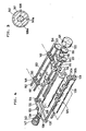
- Fig. 4 is a perspective view showing the whole sheet feeding apparatus in the printer; and
- Fig. 5 is a longitudinal sectional view of a main portion of the printer.
- Fig. 6 is a sectional front view of a main portion of another embodiment of the present invention.
-
Referring first to Figs. 4 and 5 a printer case 101 a pair of upper and lower paper guide members 103 and 104 form a paper guide path 102 therebetween. A carriage 106 provided in the printer case 101 comprises a printhead 105 below the paper guide path 102. A platen 107 opposite to the printhead 105 is attached above the paper guide path 102 rotatably on a platen shaft 108 which extends through the center of the platen 107. The platen 107 is made of a cylinder of rubber in order to reduce the printing noise. A pair of upper and lower guide bars 109 and 110 are provided between side frames of the printer case 101, and a carriage 106 is supported between the guide bars 109 and 110 movably along the width of the printer.
-
In order to feed a sheet of paper between the printhead 105 and the platen 107, a first and a second paper feeding mechanisms 111 and 125 are provided at the upstream side and at the downstream side, respectively, of the printhead 105 and the platen 107 in the paper feed direction. As shown in Fig. 16, the first paper feeding mechanism 111 comprises: a pair of upper and lower feeding rollers 112 and 114; roller shafts 113 and 115 which extend through the feeding rollers 112 and 114 and are rotatably supported between the side frames of the printer case 101; and gears 116 and 117 which are engaged with each other at each one end of the roller shafts 113 and 115. The upper roller shaft 113 projects for a determined length from the gear 116, and the projecting end of the roller shaft 113 is provided with a driving gear 118. The driving gear 118 is engaged with a first and a second intermediate gears 119 and 120, and finally engaged with an output gear 123 of an output shaft 122 of a drive motor 121. The other end of the upper roller shaft 113 is provided with a driving pulley 124 having teeth around its periphery.
-
The second paper feeding mechanism 125 comprises: a pair of upper and lower feeding rollers 126 and 128; roller shafts 127 and 129 which extend through the feeding rollers 126 and 128 and are rotatably supported between the side frames of the printer case 101; and gears 130a and 130b which are engaged with each other at each end of the roller shaft 127 and 129. At the other end of the upper roller shaft 127, a driven pulley 131 having teeth around its periphery is located corresponding to the driving pulley 124. An endless toothed belt 132 encircles the driving pulley 124 and the driven pulley 131 by way of a tension pulley 133 in such a manner that teeth provided on the inner face of the belt 132 are engaged with the teeth on the driving pulley 124 and those on the driven pulley 131. Upon the operation of the drive motor 121, the feeding rollers 112, 114, 126 and 128 in the first and second paper feeding mechanisms 111 and 125 are synchronously rotated.
-
As described above, the first and second paper feeding mechanisms 111 and 125 are located before and after the platen 107 in such a manner that a contact point of the feeding rollers 112 and 114 and that of the feeding rollers 126 and 128 are both positioned substantially on a tangent line of the circumference of the platen 107.
-
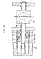
As shown in Fig. 1, both ends of the platen shaft 108 are rotatably supported in bearings 136 and 137 on side frames 134 and 135. One end of the platen shaft 108 projects for a determined length through the bearing 136, and the projecting portion of the platen shaft 108 are provided with a collar 138, a spring 140, a friction member 141, an intermediate member 143 and an operation knob 147.
-
The collar 138 is rotatably attached to the platen shaft 108. As shown in Fig. 2, the periphery of the collar 138 is provided with teeth 139 which are engaged with the teeth on the inner surface of the toothed belt 132. Consequently, the collar 138 is rotated together with the toothed belt 132.
-
Referring to Fig. 1, , the friction member 141 is attached to the platen shaft 108 movably in the axial direction of the platen shaft 108 and rotatably together with the platen shaft 108. As shown in Fig. 3 , a center hole of the friction member 141 has a contact surface 141a which is in contact with a corresponding contact surface 108a formed on the chamfered periphery of the platen shaft 108. The friction member 141 is pressed into contact with an intermediate member 143, which will be described later, by a compression spring 140 surrounding the platen shaft 108 between the friction member 141 and the collar 138. A friction disk 142 is provided on one side face of the friction member 141 opposite to the intermediate member 143 so that the friction disc 142 is in contact with the intermediate member 143 in order to transmit a torque therebetween.
-
The intermediate member 143 is rotatably attached to the platen shaft 108 and secured by a snap ring 144. From the outer rim of one face of the intermediate member 143 opposite to the collar 138, a ring portion 143a projects toward the collar 138, thereby surrounding the friction member 141. An end face of the ring portion 143a and the opposite face of the collar 138 are provided with engaging teeth 145 and 146, respectively, which are engaged with each other so that the intermediate member 143 and the collar 138 can be rotated together with each other.
-
The operation knob 147 is rotatably attached to the platen shaft 108 and splined with the intermediate member 143 in such a manner that the operation knob 147 and the intermediate member 143 can be rotated together with each other.
-
So structured as described above, the platen shaft 108 is rotated in the following manner. Referring to Fig. 1, first, a torque caused by the drive motor 121 is transmitted from the driving pulley 124 on the upper roller shaft 113 of the first paper feeding mechanism 111 to the collar 138 via the toothed belt 132. This torque on the collar 138 is transmitted to the intermediate member 143, the friction member 141, and finally to the platen shaft 108. Alternatively, a torque caused by turning the operation knob 147 is transmitted to the collar 138 via the intermediate member 143, from which the torque is transmitted to the platen shaft 108 via the friction member 142.
-
As shown in Figs.4 and 5, a pair of pin tractors 148 are positioned in one side area of the printer case 101 so as to feed a sheet of paper toward the feeding rollers 112 and 114 of the first paper feeding mechanism 111. Each pin tractor 148 mainly comprises a driving pulley 149, a driven pulley 150, and a feeding belt 151 wound around both pulleys 149 and 150. Pins 152 provided on the periphery of the feeding belt 151 fit in pin feed holes spaced along the outer edges of a continuous form at particular intervals. A square driving shaft 153 extends through the driving pulley 149, and one end of the shaft 153 is connected with a pin tractor driving gear 154 which is engaged with the first intermediate gear 119.
-
In order to feed cut sheets of paper toward the feeding rollers 112 and 114 of the first paper feeding mechanism 111, a manual guide plate 155 is supported above the pin tractors 148 pivotably on a pin 156 to be positioned at either a horizontal state illustrated by a solid line in Fig. 17 or a slant state illustrated by an interrupted line.
-
Referring to Fig.4, ,when the drive motor 121 is operated, the torque on the output shaft 122 is transmitted to the driving shaft 153 of the pin tractors 148 via the output gear 123 and the first intermediate gear 119, thereby rotating the feeding belt 151 in a certain direction. This rotation of the feeding belt 151 carries a continuous form toward the first paper feeding mechanism 111. Simultaneously, the torque on the output shaft 122 of the driving motor 121 is also transmitted to the driving gear 118 of the first paper feeding mechanism 111 via the output gear 123 and the first and the second intermediate gears 119 and 120. Consequently, the upper feeding roller 112 is rotated together with the upper roller shaft 113 in a certain direction, and simultaneously the lower feeding roller 114 is rotated together with the lower roller shaft 115 via the gears 116 and 117. In the second paper feeding mechanism 125, the upper feeding roller 126 is rotated together with the upper roller shaft 127 in a certain direction via the driving pulley 124, the toothed belt 132 and the driven pulley 131. Simultaneously, the lower feeding roller 128 is rotated together with the lower roller shaft 129 via the gears 130a and 130b. The sheet transferred by the pin tractors 148 is fed onto the paper guide path 102 by the rotation of the feeding rollers 112, 114, 126 and 128 in the first and second paper feeding mechanisms 111 and 125. Advancing between the printhead 105 and the platen 107, the sheet is discharged from an outlet 157 on the printer case 101.
-
Next, the process of rotating the platen 107 is described in detail with reference to Figs. 1 and 2. Upon the rotation of the toothed belt 132, the collar 138 engaged with the toothed belt 132 is rotated around the platen shaft 108. The torque transmitted from the toothed belt 132 to the collar 138 is then transmitted to the intermediate member 143 via the engaging teeth 145 and 146. The torque on the intermediate member 143 is transmitted to the platen shaft 108 via the friction disk 142 on the friction member 141. If the torque on the intermediate member 143 is greater than the friction driving force between the intermediate member 143 and the friction disk 142, the intermediate member 143 slips over the friction disk 142, thereby interrupting the torque transmission to the platen shaft 108. Alternatively, if the torque on the intermediate member 143 is not greater than the friction driving force between the intermediate member 143 and the friction disk 142, then, the torque is transmitted from the intermediate member 143 to the platen shaft 108 via the friction disk 142, thereby rotating the platen 107 little by little.
-
When the sheet is advanced for a determined distance, e.g., a distance corresponding to a single line of a space, the drive motor 121 stops. At this moment, the platen 107 is rotated for a little amount by the inertia force due to its own weight. The torque caused by the inertia force of the platen 107 is transmitted to the collar 138 to such a degree that it is not greater than the friction driving force between the friction disk 142 on the friction member 141 and the intermediate member 142. The torque thus transmitted to the collar 138 is, however, so small that it does not cause the feeding rollers 112, 114, 126, and 126 to rotate via the collar 138 and the toothed belt 132. Even when the torque caused by the inertia force of the platen 107 is greater than the friction driving force between the friction disk 142 and the intermediate member 143, the friction disk 142 slips over the intermediate member 143, thereby interrupting the torque transmission from the platen 107 to the toothed belt 132 wound around the collar 138. More specifically, the torque due to the inertia force of the platen 107 can be kept from being transmitted to the upper roller shafts 113 nor 127 via the collar 138, the toothed belt 132 and the driving and driven pulleys 124 and 131. The inertia force of the platen 107, therefore, does not cause any of the feeding rollers 112, 114, 126 and 128 to rotate. As a consequence, the sheet of paper is fed exactly for a determined distance without excessive advancement, so that the printhead 105 executes printing on the sheet by moving along the platen 107.
-
Next, an explanation will be given for the method of advancing a sheet by turning the operation knob 147 by hand. When the operation knob 147 is turned to rotate in a certain direction, the torque on the operation knob 147 is sequentially transmitted to: the intermediate member 143; the collar 138; the toothed belt 132; the driving and driven gears 124 and 131; and finally to the upper roller shafts 113 and 127 in the first and second paper feeding mechanisms 111 and 125, thereby rotating the feeding rollers 112, 114, 126 and 128. Upon the rotation of the upper roller shaft 112, the feeding belt 151 on the pin tractor 148 is activated by way of: the driving gear 118; the second intermediate gear 120; the first intermediate gear 119; and the pin tractor driving gear 154, thereby advancing the sheet through manual operation. Simultaneously the torque on the operation shaft 147 is partially transmitted to the platen shaft 108 to such a degree that the transmitted torque is not greater than the friction driving force between the intermediate member 143 and the friction disk 142 on the friction member 141. As a consequence, the platen shaft 108 rotates the platen 107.
-
Hereinafter, asecond embodiment of the invention will be described with reference to Fig6. The second embodiment is different from thefirst embodiment in the assembly of the collar 138, the friction member 141, the intermediate member 143 and the operation knob 147 to the platen shaft 108 of the platen 107. Since the rest of the structure is almost the same as that of the first embodiment, the explanation thereof is omitted. In this embodiment, the collar 138, the friction member 141 and the intermediate member 143 are rotatably attached on the platen shaft 108. The spring 140 is provided between the collar 138 and the friction member 141 so as to force the friction disk 142 of the friction member 141 into contact with a side face of the intermediate member 143. The friction member 141 is splined with the collar 138 so as to move along the platen shaft 108 and normally transmit a torque to the collar 138.
-
The intermediate member 143 can move toward the collar 138 along the platen shaft 108 and the opposite face of the intermediate member 143 to the collar 138 is secured by the snap ring 144. Clutch portions 158 and 159 are provided on the opposing faces of the intermediate member 143 and the collar 138, respectively, in such a manner that the clutch portions 158 and 159 are normally separate from each other and that they are engaged with each other when the intermediate member 143 is brought into contact with the collar 138 against the spring 140.
-
The operation knob 147 is attached to one end of the platen shaft 108 so as to rotate together with the platen shaft 108. The operation knob 147 can move along the platen shaft 108 together with the intermediate member 143 until the clutch portion 159 on the intermediate member 143 is engaged with the opposite clutch portion 158 on the collar 138. The operation knob 147 is splined with the intermediate member 143 so as to transmit a torque therebetween.
-
So structured as described above, the torque is transmitted from the first and second paper feeding mechanisms 111 and 125 to the collar 138 via the toothed belt 132. Thereafter, the torque is sequentially transmitted to: the friction member 141; the intermediate member 143; the operation knob 147; and finally to the platen shaft 108. In case of advancing a sheet by manual operation of the operation knob 147, the operation knob 147 is first pushed until the intermediate member 143 is brought into contact with the collar 138, thereby engaging the clutch portion 159 on the intermediate member 143 with the clutch portion 158 on the collar 138. Thereafter, when the operation knob 147 is turned to rotate in a determined direction, the torque on the operation knob 147 is transmitted directly to the platen shaft 108 and also transmitted to the collar 138 via the intermediate member 143 and the clutch portions 158 and 159.
-
As many apparently widely different embodiments of this invention may be made without departing from the spirit and scope thereof, it is to be understood that the invention is not limited to the specific embodiments thereof except as defined in the appended claims.