EP0431689B1 - Packer and service tool assembly - Google Patents
Packer and service tool assembly Download PDFInfo
- Publication number
- EP0431689B1 EP0431689B1 EP90203167A EP90203167A EP0431689B1 EP 0431689 B1 EP0431689 B1 EP 0431689B1 EP 90203167 A EP90203167 A EP 90203167A EP 90203167 A EP90203167 A EP 90203167A EP 0431689 B1 EP0431689 B1 EP 0431689B1
- Authority
- EP
- European Patent Office
- Prior art keywords
- packer
- ratchet
- ring
- sleeve
- ratchet sleeve
- Prior art date
- Legal status (The legal status is an assumption and is not a legal conclusion. Google has not performed a legal analysis and makes no representation as to the accuracy of the status listed.)
- Expired - Lifetime
Links
Images
Classifications
-
- E—FIXED CONSTRUCTIONS
- E21—EARTH DRILLING; MINING
- E21B—EARTH DRILLING, e.g. DEEP DRILLING; OBTAINING OIL, GAS, WATER, SOLUBLE OR MELTABLE MATERIALS OR A SLURRY OF MINERALS FROM WELLS
- E21B23/00—Apparatus for displacing, setting, locking, releasing, or removing tools, packers or the like in the boreholes or wells
- E21B23/06—Apparatus for displacing, setting, locking, releasing, or removing tools, packers or the like in the boreholes or wells for setting packers
-
- E—FIXED CONSTRUCTIONS
- E21—EARTH DRILLING; MINING
- E21B—EARTH DRILLING, e.g. DEEP DRILLING; OBTAINING OIL, GAS, WATER, SOLUBLE OR MELTABLE MATERIALS OR A SLURRY OF MINERALS FROM WELLS
- E21B33/00—Sealing or packing boreholes or wells
- E21B33/10—Sealing or packing boreholes or wells in the borehole
- E21B33/12—Packers; Plugs
- E21B33/129—Packers; Plugs with mechanical slips for hooking into the casing
- E21B33/1295—Packers; Plugs with mechanical slips for hooking into the casing actuated by fluid pressure
-
- E—FIXED CONSTRUCTIONS
- E21—EARTH DRILLING; MINING
- E21B—EARTH DRILLING, e.g. DEEP DRILLING; OBTAINING OIL, GAS, WATER, SOLUBLE OR MELTABLE MATERIALS OR A SLURRY OF MINERALS FROM WELLS
- E21B43/00—Methods or apparatus for obtaining oil, gas, water, soluble or meltable materials or a slurry of minerals from wells
- E21B43/02—Subsoil filtering
- E21B43/04—Gravelling of wells
Definitions
- the invention relates generally to apparatus for preparing a production well such as a gas or oil well. More specifically, the invention relates to a gravel packing system used in a well to place gravel in casing perforations of the well at a formation site.
- An oil well borehole which is being prepared for oil and/or gas production generally includes a steel casing supported by a cement casing in the annulus around the steel casing.
- the cement casing isolates two or more zones such as, for example, a production zone from brine.
- a number of perforations are formed in the casings at the formations thus providing fluid communication between the formation and the well.
- a production string wellstring provides a fluid conduit through which the oil or gas travels to the surface.
- a portion of the production string opposite the casing perforations is referred to as the screen.
- the screen is made of tubing with numerous holes formed in the tubing wall. Wire is then wrapped around the tubing so as to achieve a desired mesh which permits the formation products to flow up the production string but blocks undesired deposits entrained in the oil or gas.
- a serious problem encountered during extraction is the presence of formation sand in the product. Because of the high fluid pressures involved, there is a sand-blasting effect on the screen which can quickly lead to premature weardown of the screen and tubing.
- a common technique used to overcome this blasting effect of the formation sand is to pack gravel in the casing perforations and in the annulus around the screen.
- the gravel acts as a trap which blocks the formation sand from reaching the screen but which permits permeability for the product medium such an oil to flow through to the production string.
- the gravel is mixed with water and pumped as a slurry down the well to the formation site.
- the gravel must be effectively packed to prevent voids.
- When packed under pressure the slurry dehydrates with the fluid being returned to the surface via a washpipe.
- the gravel packing process is carried out using a packer apparatus and a service tool.
- the packer is an apparatus which in normal use is placed in the well and directs the slurry to flow to the desired location for packing.
- the packer performs this task by separating the annulus between the string and casing into two sealed off regions, the upper annulus above the packer and the lower annulus which is below the packer.
- the packer is provided with a plurality of slips which can be hydraulically actuated to bite into the steel casing to support or set the packer in the well hole.
- a plurality of packer sealing elements are compressed and expanded radially outwardly to seal off the upper annulus from the lower annulus.
- the hydraulic actuation of the packer is effected by the use of another tool called the service tool which may also be reffered to as a running tool or cross-over tool.
- the service tool is screwed into the packer and booth tools are run into the well with a work-string.
- the service tool provides a conduit via tubing for hydraulically setting the packer and provides cross-over ports for carrying the slurry from the tubing over into the lower annulus through openings or squeeze ports in the packer housing.
- the service tool In normal use the service tool is removed from the well after the packing operation is completed and the packer remains set in the well. After the service tool is removed the production string can be run into the well and extraction of the formation products is carried out.
- Another problem with the known packers and service tool is the tendency for the packer assembly to relax when the setting pressure is removed thus reducing the effectiveness of the packer seal elements and the slips which support the packer in the casing.
- Another significant problem is that when it becomes necessary to perform a run to retrieve the packer, the packer must be pulled out with a tremendous force necessary to free the packer from the casing due to the high slip load.
- US-A-4,289,200 describes a retrievable well packer with a collapsible latch system engaged with a mandrel. Retrieval can be achieved by shifting the supporting sleeve so as to release the latch system.
- the invention overcomes the above-mentioned problems by providing a service tool which can be hydraulically disengaged from the packer without applying torque to the wellstring or the service tool.
- the invention broadly contemplates a ratchet mechanism for maintaining seal integrity and slip load between the packer and casing after the setting pressure is removed.
- the ratchet mechanism can be selectively disengaged to permit a substantial reduction in the slip load to facilitate removal of the packer after setting.
- the ratchet sleeve has a lower end formed with slotted ratchet finger elements 170 (only 2 shown) somewhat similar to the service tool release collet fingers 140 in that the fingers 170 can be collapsed radially inwardly although, unlike the tool release collet fingers 140, the ratchet fingers 170 are not designed or biased to naturally collapse or relax inwardly out of engagement from the ring.
- the T-shaped ratchet ring 114 is retained within a recess 111 in the housing 112. As shown in FIGS. 1B and 1C the ratchet ring 114 and ratchet fingers 170 have cooperating trapping threads 172 which mesh and act to prevent upward movement of the ratchet sleeve 98.
- the ratchet ring is a split ring design as shown in FIG. 1D. The split 115 permits the ring 114 to compressively engage with the ratchet sleeve 98 to ensure a good mesh of the trapping threads 172.
- the mandrel 60 and ratchet sleeve 98 expand the ring outwardly within the recess 111 to provide a positive ratcheting function as the ratchet sleeve slides downward during setting of the packer.
- the teeth of the ratchet fingers 170 are held in engagement with the teeth of the ratchet ring 114 because the ratchet sleeve 98 is supported by a larger outer diameter portion 60a the packer mandrel 60 (see EP-A-216 417, either figures 2B or 3B). This is important because the packer elements and slip are adjacent the ratchet sleeve 98. Thus, if it were not for the packer mandrel 60, the setting load on the elements and slips could cause the ratchet sleeve fingers 170 to collapse out of engagement with the ratchet ring 114.
- the packer setting load of the elements and slips is trapped between the ratchet sleeve 98 and the ratchet ring 114.
- the ratchet mechanism therefore, prevents relaxation of the packer setting members after the tubing setting pressure is bled off. That is, without the described ratchet mechanism, the setting sleeve would tend to shift upwardly and permit the elements and slips to relax somewhat resulting in less of a setting load to hold the packer 30b in the casing.
- a very useful feature of the above-described ratchet mechanism is that is can be released so as to permit an easier retrieval of the packer 30b after the packer is set. This is shown primarily in FIG. 1.
- the production string (not shown) is replaced with a workstring which is latched into the packer housing 50 in a conventional manner.
- the packer 30a is picked up with about a 31.500 Kg. pull above the pipe weight.
- the packer housing 50 is supported on the lower setting housing 58 and the packer mandrel 60 via a lower coupling. Since the service tool 30b is no longer in the well, the packer mandrel 60 can move upwardly in the well 10.
- the housing 50 is only restrained by the shear bolts 62 (see the patent application EPA 86 201 514.6, figure 3C).
- the described upward movement of the packer housing 50 in turn causes upward movement of the lower coupling to which it is attached.
- the upper end of the coupling has a beveled face 174 which cams against tapered lower ends 176 of the ratchet sleeve fingers 170.
- the packer mandrel 60 (which moves upwardly with the housing 50 and coupling 56 and may now be considered a packer mandrel assembly) has a reduced outer diameter portion 60b which forms a recess or depression 178 into which the fingers 170 are pushed or collapsed by the camming face 174 of the coupling 56.
- the recess 178 slides up opposite the fingers 170 (as illustrated in FIG. 1) and the fingers are pushed inwardly so as to disengage the trapping threads 172 on the ratchet sleeve fingers 170 and the ratchet ring 114.
- the split ratchet ring 114 will tend to also collapse around the depressed fingers 170, however, the T-shape of the ring 114 catches on the housing 112 and restrains the ring 114 from collapsing back into engagement.
- gap 180 is present between the ring and fingers trapping teeth 172.
- the described inward collapse of the ratchet sleeve fingers permits the ring to pull up on the elements and releases the setting load on the elements and slips and the packer 30b can then be retrieved with a much lighter pull load.
- the packer mandrel recess 178 is below the setting load zone of the elements and slips so that the larger outer diameter of the mandrel 60 holds the ratchet mechanism engaged.
- the setting load is trapped by the ratchet mechanism as described in the patent application EPA 86 201 514.6 (FIG. 3C).
- the step-up which occurs between the smaller and larger outer diameters of the mandrel 60 is approximately positioned opposite the ratchet ring 114 prior to and after setting of the packer 30b.
- This relative position of the mandrel 60 with respect to the ring 114 and setting members cannot change until the packer release screws 62 are sheared off.
- the packer mandrel 60 cannot accidentally slide up so as to have the recess 178 under the ratchet ring and sleeve during setting because the mandrel 60 is joined to the service tool 30b and workstring 32 via a disengageable coupling during running in and setting.
- ratchet mechanism that traps the setting load on the elements and slips is located below the elements and slips thereby isolating the packer releasing mechanism from debris. This helps minimize releasing problems.
Description
- The present application is a divisional application of EPA 86 201 514.6 filed on Sept. 2,86 (EP-A-0 216 417).
- The invention relates generally to apparatus for preparing a production well such as a gas or oil well. More specifically, the invention relates to a gravel packing system used in a well to place gravel in casing perforations of the well at a formation site.
- An oil well borehole which is being prepared for oil and/or gas production generally includes a steel casing supported by a cement casing in the annulus around the steel casing. The cement casing isolates two or more zones such as, for example, a production zone from brine. A number of perforations are formed in the casings at the formations thus providing fluid communication between the formation and the well. A production string wellstring provides a fluid conduit through which the oil or gas travels to the surface. A portion of the production string opposite the casing perforations is referred to as the screen. The screen is made of tubing with numerous holes formed in the tubing wall. Wire is then wrapped around the tubing so as to achieve a desired mesh which permits the formation products to flow up the production string but blocks undesired deposits entrained in the oil or gas.
- A serious problem encountered during extraction is the presence of formation sand in the product. Because of the high fluid pressures involved, there is a sand-blasting effect on the screen which can quickly lead to premature weardown of the screen and tubing.
- A common technique used to overcome this blasting effect of the formation sand is to pack gravel in the casing perforations and in the annulus around the screen. The gravel acts as a trap which blocks the formation sand from reaching the screen but which permits permeability for the product medium such an oil to flow through to the production string.
- The gravel is mixed with water and pumped as a slurry down the well to the formation site. The gravel must be effectively packed to prevent voids. When packed under pressure the slurry dehydrates with the fluid being returned to the surface via a washpipe.
- The gravel packing process is carried out using a packer apparatus and a service tool. Generally, the packer is an apparatus which in normal use is placed in the well and directs the slurry to flow to the desired location for packing. The packer performs this task by separating the annulus between the string and casing into two sealed off regions, the upper annulus above the packer and the lower annulus which is below the packer. The packer is provided with a plurality of slips which can be hydraulically actuated to bite into the steel casing to support or set the packer in the well hole. A plurality of packer sealing elements are compressed and expanded radially outwardly to seal off the upper annulus from the lower annulus.
- The hydraulic actuation of the packer is effected by the use of another tool called the service tool which may also be reffered to as a running tool or cross-over tool. The service tool is screwed into the packer and booth tools are run into the well with a work-string. The service tool provides a conduit via tubing for hydraulically setting the packer and provides cross-over ports for carrying the slurry from the tubing over into the lower annulus through openings or squeeze ports in the packer housing.
- In normal use the service tool is removed from the well after the packing operation is completed and the packer remains set in the well. After the service tool is removed the production string can be run into the well and extraction of the formation products is carried out.
- The packer and service tool assemblies known heretofore, however, have numerous drawbacks and very undesirable limitations. For example, because the service tool and packer are screwed together, in order to remove the service tool it must be unscrewed from the packer via the workstring. This procedure requires the application of high torque levels on the workstring in order to rotate and back out the service tool from the packer. This is particularly difficult in highly deviated (curved or nonvertical) wells wherein the torque applied to the workstring is prohibitive.
- Another problem with the known packers and service tool is the tendency for the packer assembly to relax when the setting pressure is removed thus reducing the effectiveness of the packer seal elements and the slips which support the packer in the casing.
- Another significant problem is that when it becomes necessary to perform a run to retrieve the packer, the packer must be pulled out with a tremendous force necessary to free the packer from the casing due to the high slip load.
- US-A-4,289,200 describes a retrievable well packer with a collapsible latch system engaged with a mandrel. Retrieval can be achieved by shifting the supporting sleeve so as to release the latch system.
- The invention overcomes the above-mentioned problems by providing a service tool which can be hydraulically disengaged from the packer without applying torque to the wellstring or the service tool. The invention broadly contemplates a ratchet mechanism for maintaining seal integrity and slip load between the packer and casing after the setting pressure is removed. The ratchet mechanism can be selectively disengaged to permit a substantial reduction in the slip load to facilitate removal of the packer after setting.
- These and other aspects of the present invention will be fully described in and understood from the following specification in view of the accompanying drawings.
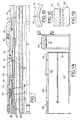
- FIG. 1 is a longitudinal section of a portion of the packer and service tool assembly showing a ratchet mechanism according to the present invention Just as it is being released to permit retrieval of the packer.
- FIG. 1A is an exploded view of a ratchet mechanism according to the present invention;
- FIGS. 1B and 1C are enlarged views of trapping teeth on a ratchet sleeve and T-shaped ratchet ring; and
- FIG. 1D is a partial plan view of the ratchet ring shown in FIG. 1A showing a split ring design.
- The ratchet mechanism and packer release assembly will now be described with reference to FIG.1 - 1D.
- As shown in FIG.1A, the ratchet sleeve has a lower end formed with slotted ratchet finger elements 170 (only 2 shown) somewhat similar to the service tool release collet fingers 140 in that the
fingers 170 can be collapsed radially inwardly although, unlike the tool release collet fingers 140, theratchet fingers 170 are not designed or biased to naturally collapse or relax inwardly out of engagement from the ring. - The T-
shaped ratchet ring 114 is retained within arecess 111 in thehousing 112. As shown in FIGS. 1B and 1C theratchet ring 114 andratchet fingers 170 have cooperatingtrapping threads 172 which mesh and act to prevent upward movement of theratchet sleeve 98. The ratchet ring is a split ring design as shown in FIG. 1D. Thesplit 115 permits thering 114 to compressively engage with theratchet sleeve 98 to ensure a good mesh of thetrapping threads 172. That is, themandrel 60 andratchet sleeve 98 expand the ring outwardly within therecess 111 to provide a positive ratcheting function as the ratchet sleeve slides downward during setting of the packer. - The teeth of the
ratchet fingers 170 are held in engagement with the teeth of theratchet ring 114 because theratchet sleeve 98 is supported by a larger outer diameter portion 60a the packer mandrel 60 (see EP-A-216 417, either figures 2B or 3B). This is important because the packer elements and slip are adjacent theratchet sleeve 98. Thus, if it were not for thepacker mandrel 60, the setting load on the elements and slips could cause theratchet sleeve fingers 170 to collapse out of engagement with theratchet ring 114. - Thus, the packer setting load of the elements and slips is trapped between the
ratchet sleeve 98 and theratchet ring 114. The ratchet mechanism, therefore, prevents relaxation of the packer setting members after the tubing setting pressure is bled off. That is, without the described ratchet mechanism, the setting sleeve would tend to shift upwardly and permit the elements and slips to relax somewhat resulting in less of a setting load to hold the packer 30b in the casing. - A very useful feature of the above-described ratchet mechanism is that is can be released so as to permit an easier retrieval of the packer 30b after the packer is set. This is shown primarily in FIG. 1.
- Situations can arise wherein it becomes necessary to release the packer from the well. The known packers are removed by applying a tremendous upward force via a workstring which is latched into the packer housing. This is a difficult and expensive operation because of the higt setting load holding the packer in the casing.
- The present invention overcomes this problem in the following way. To retrieve the packer 30b, the production string (not shown) is replaced with a workstring which is latched into the
packer housing 50 in a conventional manner. Once latching is confirmed the packer 30a is picked up with about a 31.500 Kg. pull above the pipe weight. As described hereinabove, thepacker housing 50 is supported on thelower setting housing 58 and thepacker mandrel 60 via a lower coupling. Since the service tool 30b is no longer in the well, thepacker mandrel 60 can move upwardly in thewell 10. Thus, thehousing 50 is only restrained by the shear bolts 62 (see the patent application EPA 86 201 514.6, figure 3C). When the 31.500 Kg. pull is applied to thepacker housing 50 it is sufficient to shear off thebolts 62 and a portion of thehousing 50 telescopes up into thelower housing 58 as ilustrated in FIG. 1 (keep in mind that thelower housing 58 is restrained from upward movement because it is coupled to the lower slip bowl which is restrained by the elements and slips set in the casing). - The described upward movement of the
packer housing 50 in turn causes upward movement of the lower coupling to which it is attached. The upper end of the coupling has abeveled face 174 which cams against tapered lower ends 176 of theratchet sleeve fingers 170. - The packer mandrel 60 (which moves upwardly with the
housing 50 andcoupling 56 and may now be considered a packer mandrel assembly) has a reducedouter diameter portion 60b which forms a recess ordepression 178 into which thefingers 170 are pushed or collapsed by thecamming face 174 of thecoupling 56. As thecoupling 56 is pulled further upwards from the position shown in FIG. 1, therecess 178 slides up opposite the fingers 170 (as illustrated in FIG. 1) and the fingers are pushed inwardly so as to disengage the trappingthreads 172 on theratchet sleeve fingers 170 and theratchet ring 114. Of course, thesplit ratchet ring 114 will tend to also collapse around thedepressed fingers 170, however, the T-shape of thering 114 catches on thehousing 112 and restrains thering 114 from collapsing back into engagement. Thus,gap 180 is present between the ring andfingers trapping teeth 172. The described inward collapse of the ratchet sleeve fingers permits the ring to pull up on the elements and releases the setting load on the elements and slips and the packer 30b can then be retrieved with a much lighter pull load. - It should be noted that when the packer is set, or prior to the packer being set, the
packer mandrel recess 178 is below the setting load zone of the elements and slips so that the larger outer diameter of themandrel 60 holds the ratchet mechanism engaged. Thus, the setting load is trapped by the ratchet mechanism as described in the patent application EPA 86 201 514.6 (FIG. 3C). As shown in said FIG. 3C, the step-up which occurs between the smaller and larger outer diameters of themandrel 60 is approximately positioned opposite theratchet ring 114 prior to and after setting of the packer 30b. This relative position of themandrel 60 with respect to thering 114 and setting members cannot change until the packer release screws 62 are sheared off. Thepacker mandrel 60 cannot accidentally slide up so as to have therecess 178 under the ratchet ring and sleeve during setting because themandrel 60 is joined to the service tool 30b and workstring 32 via a disengageable coupling during running in and setting. - Also note that ratchet mechanism that traps the setting load on the elements and slips is located below the elements and slips thereby isolating the packer releasing mechanism from debris. This helps minimize releasing problems.
Claims (6)
- Packer assembly (30a, 30b) of the type having a housing (50) and a plurality of hydraulically actuated seal and slip means for setting the packer (30a, 30b) in a well casing comprising a releasable ratchet mechanism for trapping setting loads so as to prevent relaxation of the setting means after setting pressure is released, said seal and slip means being actuated by sliding means for compressing said seal and slip means against an element secured to the housing and stationary with respect to said sliding means, said sliding means moving relative to the housing under force of hydraulic pressure ; said ratchet mechanism being releasable thereby permitting relaxation of said seal and slip means and facilitating retrieval of the packer (30a, 30b) from the well, said ratchet mechanism including a ratchet sleeve (98) and a ratchet ring (114), said sleeve (98) and ring (114) having cooperating trapping teeth (172) meshable in a ratcheting manner, said ratchet sleeve (98) being adapted for sliding movement with said sliding means axially through said ratchet ring (114) which is stationarily held in the packer (30a, 30b), and further comprising a packer mandrel assembly (60) on the packer housing (50) and joined to said seal and slip means by breakable means (162), said packer mandrel (60) assembly abutting said ratchet sleeve (98) and being stationary with respect thereto as the packer (30a, 30b) is being set, characterized in that said ratchet ring is a split T-shaped ring (114) which is adapted to collapse from a first outer diameter to a second relatively smaller outer diameter, said ratchet ring (114) being held at said first outer diameter by engagement with said ratchet sleeve (98) when said packer mandrel assembly (60) first portion is abutting said ratchet sleeve (98) so as to ensure a positive ratcheting engagement with said ratchet sleeve fingers (170), said ratchet ring (114) collapsing to said second outer diameter when said ratchet sleeve fingers (170) are cammed and collapsed inwardly, said second outer diameter being great enough to prevent said ratchet ring (114) from engaging said collapsed ratchet sleeve fingers (170) in a ratcheting manner.
- Packer as set forth in claim 1 characterized in that said ratchet ring (114) is held in a ring housing member of the packer (30a, 30b) held by said seal and slip means, said ring housing (111) preventing said ratchet ring (114) from collapsing inwardly to an outer diameter less than said second outer diameter.
- Packer as set forth in claim 1 or 2, characterized in that a portion of said ratchet sleeve (98) abuts said seal and slip means such that the setting force is applied between the casing (50) and said ratchet sleeve (98) and trapped due to said meshed trapping teeth (172).
- Packer as set forth in claim 1 or 2 characterized in that said ratchet sleeve (98) is collet shaped and includes a plurality of slotted fingers (170) which are collapsible inwardly so as to disengage said ratchet sleeve (98) from said ratchet (114) ring.
- Packer as set forth in claim 1 or 2 characterized in that said packer mandrel assembly (60) and housing (50) are moveable with respect to each of said ratchet sleeve seal and slip means and ratchet ring (114) after said breakable means (162) are broken by an upward pull on the housing, said packer mandrel assembly (60) having a first outer diameter portion and a recessed relatively smaller second outer diameter portion, said first portion substantially engaging said ratchet sleeve fingers (170) when the packer (30a, 30b) is set so as to trap the setting load, said packer mandrel assembly (60) moving with the housing (50) after said breakable means (162) is broken so as to position said recessed second portion substantially opposite said ratchet sleeve fingers (170) thereby permitting said ratchet sleeve fingers (170) to collapse inwardly.
- Packer as set forth in claim 1 or 2 characterized in that said packer mandrel assembly (60) includes a cam element engageable with free ends of said ratchet sleeve fingers (170) as said packer mandrel assembly (60) moves with respect to said ratchet sleeve (98), said cam elements causing said fingers (170) to collapse inwardly thereby releasing said ratchet mechanism.
Applications Claiming Priority (3)
| Application Number | Priority Date | Filing Date | Title |
|---|---|---|---|
| US774979 | 1985-09-11 | ||
| US06/774,979 US4660637A (en) | 1985-09-11 | 1985-09-11 | Packer and service tool assembly |
| EP86201514A EP0216417A3 (en) | 1985-09-11 | 1986-09-02 | Packer and service tool assembly |
Related Parent Applications (1)
| Application Number | Title | Priority Date | Filing Date |
|---|---|---|---|
| EP86201514.6 Division | 1986-09-02 |
Publications (2)
| Publication Number | Publication Date |
|---|---|
| EP0431689A1 EP0431689A1 (en) | 1991-06-12 |
| EP0431689B1 true EP0431689B1 (en) | 1995-03-01 |
Family
ID=25102924
Family Applications (2)
| Application Number | Title | Priority Date | Filing Date |
|---|---|---|---|
| EP86201514A Withdrawn EP0216417A3 (en) | 1985-09-11 | 1986-09-02 | Packer and service tool assembly |
| EP90203167A Expired - Lifetime EP0431689B1 (en) | 1985-09-11 | 1986-09-02 | Packer and service tool assembly |
Family Applications Before (1)
| Application Number | Title | Priority Date | Filing Date |
|---|---|---|---|
| EP86201514A Withdrawn EP0216417A3 (en) | 1985-09-11 | 1986-09-02 | Packer and service tool assembly |
Country Status (6)
| Country | Link |
|---|---|
| US (1) | US4660637A (en) |
| EP (2) | EP0216417A3 (en) |
| BR (1) | BR8604329A (en) |
| CA (1) | CA1255584A (en) |
| DE (1) | DE3650252D1 (en) |
| NO (1) | NO863621L (en) |
Families Citing this family (30)
| Publication number | Priority date | Publication date | Assignee | Title |
|---|---|---|---|---|
| US4862957A (en) * | 1985-09-11 | 1989-09-05 | Dowell Schlumberger Incorporated | Packer and service tool assembly |
| US4754812A (en) * | 1987-03-23 | 1988-07-05 | Baker Oil Tools, Inc. | Dual string packer method and apparatus |
| US4940093A (en) * | 1988-09-06 | 1990-07-10 | Dowell Schlumberger Incorporated | Gravel packing tool |
| US5069280A (en) * | 1990-02-12 | 1991-12-03 | Dowell Schlumberger Incorporated | Gravel packer and service tool |
| US5207274A (en) * | 1991-08-12 | 1993-05-04 | Halliburton Company | Apparatus and method of anchoring and releasing from a packer |
| US5332038A (en) * | 1992-08-06 | 1994-07-26 | Baker Hughes Incorporated | Gravel packing system |
| US5320183A (en) * | 1992-10-16 | 1994-06-14 | Schlumberger Technology Corporation | Locking apparatus for locking a packer setting apparatus and preventing the packer from setting until a predetermined annulus pressure is produced |
| US5343954A (en) * | 1992-11-03 | 1994-09-06 | Halliburton Company | Apparatus and method of anchoring and releasing from a packer |
| GB2290812B (en) * | 1994-07-01 | 1998-04-15 | Petroleum Eng Services | Release mechanism for down-hole tools |
| US5579840A (en) * | 1994-10-05 | 1996-12-03 | Dresser Industries, Inc. | Packer running and setting tool |
| US5549161A (en) * | 1995-03-06 | 1996-08-27 | Baker Hughes Incorporated | Overpull shifting tool |
| US5941306A (en) * | 1997-10-07 | 1999-08-24 | Quinn; Desmond | Ratchet release mechanism for a retrievable well apparatus and a retrievable well apparatus |
| CA2461726C (en) * | 2001-09-28 | 2015-06-09 | Shuffle Master, Inc. | Card shuffling apparatus with automatic card size calibration |
| US7066251B2 (en) * | 2003-05-01 | 2006-06-27 | National-Oilwell, L.P. | Hydraulic jar lock |
| CA2462012C (en) * | 2004-03-23 | 2007-08-21 | Smith International, Inc. | System and method for installing a liner in a borehole |
| US8727001B2 (en) * | 2007-09-25 | 2014-05-20 | Halliburton Energy Services, Inc. | Methods and compositions relating to minimizing particulate migration over long intervals |
| US20090242189A1 (en) * | 2008-03-28 | 2009-10-01 | Schlumberger Technology Corporation | Swell packer |
| US8575273B2 (en) * | 2008-11-26 | 2013-11-05 | Schlumberger Technology Corporation | Coupling agents and compositions produced using them |
| GB0901034D0 (en) | 2009-01-22 | 2009-03-11 | Petrowell Ltd | Apparatus and method |
| US8517114B2 (en) * | 2010-02-26 | 2013-08-27 | Baker Hughes Incorporated | Mechanical lock with pressure balanced floating piston |
| US8439107B2 (en) | 2010-07-13 | 2013-05-14 | Baker Hughes Incorporated | Retrievable tool with ratchet lock feature |
| US9403962B2 (en) | 2011-12-22 | 2016-08-02 | Schlumberger Technology Corporation | Elastomer compositions with silane functionalized silica as reinforcing fillers |
| WO2015065332A1 (en) * | 2013-10-29 | 2015-05-07 | Halliburton Energy Services, Inc. | Hydraulically-metered downhole position indicator |
| US9850752B2 (en) | 2012-06-05 | 2017-12-26 | Halliburton Energy Services, Inc. | Hydraulically-metered downhole position indicator |
| US9033056B2 (en) | 2012-08-15 | 2015-05-19 | Halliburton Energy Srvices, Inc. | Pressure activated down hole systems and methods |
| US9238954B2 (en) * | 2012-08-15 | 2016-01-19 | Halliburton Energy Services, Inc. | Pressure activated down hole systems and methods |
| WO2015147787A1 (en) * | 2014-03-24 | 2015-10-01 | Halliburton Energy Services, Inc. | Cut-to-release packer with load transfer device to expand performance envelope |
| US9951578B2 (en) | 2015-10-20 | 2018-04-24 | Baker Hughes, A Ge Company, Llc | Radially expandable ratchet locking borehole barrier assembly |
| US10760363B2 (en) * | 2018-02-19 | 2020-09-01 | Baker Hughes, A Ge Company, Llc | Lock ring segments biased into locked position while retained in position with an exterior profile |
| US11118425B2 (en) * | 2019-08-19 | 2021-09-14 | Halliburton Energy Services, Inc. | Pumpdown regulator |
Family Cites Families (19)
| Publication number | Priority date | Publication date | Assignee | Title |
|---|---|---|---|---|
| GB718976A (en) * | 1951-12-13 | 1954-11-24 | Baker Oil Tools Inc | Improvements in or relating to couplings for rods, tubes, and the like |
| US2966216A (en) * | 1958-05-12 | 1960-12-27 | Baker Oil Tools Inc | Subsurface well bore anchor |
| US3237695A (en) * | 1962-11-30 | 1966-03-01 | Otis Eng Co | Hydraulically set well packer |
| US3282340A (en) * | 1963-07-05 | 1966-11-01 | Baker Oil Tools Inc | Retrievable pump and anchor apparatus |
| US3374837A (en) * | 1965-10-18 | 1968-03-26 | Page Oil Tools Inc | Retrievable packer |
| US3552489A (en) * | 1968-12-04 | 1971-01-05 | Schlumberger Technology Corp | Well packer apparatus |
| US3695352A (en) * | 1970-09-21 | 1972-10-03 | Schlumberger Technology Corp | Retrievable well packer apparatus |
| US4049055A (en) * | 1971-04-30 | 1977-09-20 | Brown Oil Tools, Inc. | Gravel pack method, retrievable well packer and gravel pack apparatus |
| US3746093A (en) * | 1972-05-26 | 1973-07-17 | Schlumberger Technology Corp | Releasable locking system for a well tool |
| US3915261A (en) * | 1973-11-02 | 1975-10-28 | Dresser Ind | Shearable ratchet mechanism |
| US4078606A (en) * | 1976-12-15 | 1978-03-14 | Brown Oil Tools, Inc. | Pressure actuated holding apparatus |
| US4289200A (en) * | 1980-09-24 | 1981-09-15 | Baker International Corporation | Retrievable well apparatus |
| SU964104A1 (en) * | 1980-12-29 | 1982-10-07 | Калининское отделение Всесоюзного научно-исследовательского и проектно-конструкторского института геофизических исследований геологоразведочных скважин | Apparatus for retaining a packer |
| US4393929A (en) * | 1981-02-17 | 1983-07-19 | Ava International | Well packers and slip assemblies for use therewith |
| US4437516A (en) * | 1981-06-03 | 1984-03-20 | Baker International Corporation | Combination release mechanism for downhole well apparatus |
| US4479548A (en) * | 1983-03-17 | 1984-10-30 | Hughes Tool Company | Setting tool adapter kit |
| US4488595A (en) * | 1983-06-23 | 1984-12-18 | Neil H. Akkerman | Well tool having a slip assembly |
| US4524825A (en) * | 1983-12-01 | 1985-06-25 | Halliburton Company | Well packer |
| US4526233A (en) * | 1984-01-20 | 1985-07-02 | Baker Oil Tools, Inc. | Releasable coupling for tubing conveyed subterranean well perforating gun |
-
1985
- 1985-09-11 US US06/774,979 patent/US4660637A/en not_active Expired - Lifetime
-
1986
- 1986-01-09 CA CA000499273A patent/CA1255584A/en not_active Expired
- 1986-09-02 EP EP86201514A patent/EP0216417A3/en not_active Withdrawn
- 1986-09-02 DE DE3650252T patent/DE3650252D1/en not_active Expired - Lifetime
- 1986-09-02 EP EP90203167A patent/EP0431689B1/en not_active Expired - Lifetime
- 1986-09-10 BR BR8604329A patent/BR8604329A/en not_active IP Right Cessation
- 1986-09-10 NO NO863621A patent/NO863621L/en unknown
Also Published As
| Publication number | Publication date |
|---|---|
| NO863621D0 (en) | 1986-09-10 |
| US4660637A (en) | 1987-04-28 |
| NO863621L (en) | 1987-03-12 |
| DE3650252D1 (en) | 1995-04-06 |
| BR8604329A (en) | 1987-05-12 |
| CA1263839C (en) | 1989-12-12 |
| CA1255584A (en) | 1989-06-13 |
| EP0431689A1 (en) | 1991-06-12 |
| EP0216417A3 (en) | 1988-09-28 |
| EP0216417A2 (en) | 1987-04-01 |
Similar Documents
| Publication | Publication Date | Title |
|---|---|---|
| EP0431689B1 (en) | Packer and service tool assembly | |
| US4862957A (en) | Packer and service tool assembly | |
| US5975205A (en) | Gravel pack apparatus and method | |
| US3818986A (en) | Selective well treating and gravel packing apparatus | |
| US4848459A (en) | Apparatus for installing a liner within a well bore | |
| US4830103A (en) | Setting tool for mechanical packer | |
| US7104323B2 (en) | Spiral tubular tool and method | |
| EP0589586B1 (en) | Isolation washpipe for earth well completions and method for use in gravel packing a well | |
| US5413180A (en) | One trip backwash/sand control system with extendable washpipe isolation | |
| CA2551072C (en) | Retrievable packer assembly and system with releaseable body locking ring | |
| CA2653738C (en) | Configurable wellbore zone isolation system and related methods | |
| US5960879A (en) | Methods of completing a subterranean well | |
| US6732806B2 (en) | One trip expansion method and apparatus for use in a wellbore | |
| CA1151537A (en) | Well packer | |
| CA2434346C (en) | Retrievable packer having a positively operated support ring | |
| US5404955A (en) | Releasable running tool for setting well tool | |
| EP1392953B1 (en) | Line hanger, running tool and method | |
| GB2230287A (en) | Dual hydraulic set packer. | |
| WO2003018957A1 (en) | Expandable packer | |
| US3997006A (en) | Well tool having an hydraulically releasable coupler component | |
| US4924941A (en) | Bi-directional pressure assisted sealing packers | |
| WO2015012854A1 (en) | Retrieval of compressed packers from a wellbore | |
| US4722400A (en) | Mechanically actuated subsurface injection tool | |
| GB2240125A (en) | Packing assembly for use with reeled tubing and method of operating and removing same | |
| US5044433A (en) | Pack-off well apparatus with straight shear release |
Legal Events
| Date | Code | Title | Description |
|---|---|---|---|
| PUAI | Public reference made under article 153(3) epc to a published international application that has entered the european phase |
Free format text: ORIGINAL CODE: 0009012 |
|
| AC | Divisional application: reference to earlier application |
Ref document number: 216417 Country of ref document: EP |
|
| AK | Designated contracting states |
Kind code of ref document: A1 Designated state(s): DE FR GB IT NL |
|
| 17P | Request for examination filed |
Effective date: 19911211 |
|
| 17Q | First examination report despatched |
Effective date: 19930903 |
|
| RAP1 | Party data changed (applicant data changed or rights of an application transferred) |
Owner name: SOFITECH N.V. Owner name: COMPAGNIE DES SERVICES DOWELL SCHLUMBERGER |
|
| GRAA | (expected) grant |
Free format text: ORIGINAL CODE: 0009210 |
|
| AC | Divisional application: reference to earlier application |
Ref document number: 216417 Country of ref document: EP |
|
| AK | Designated contracting states |
Kind code of ref document: B1 Designated state(s): DE FR GB IT NL |
|
| PG25 | Lapsed in a contracting state [announced via postgrant information from national office to epo] |
Ref country code: IT Free format text: LAPSE BECAUSE OF FAILURE TO SUBMIT A TRANSLATION OF THE DESCRIPTION OR TO PAY THE FEE WITHIN THE PRE;WARNING: LAPSES OF ITALIAN PATENTS WITH EFFECTIVE DATE BEFORE 2007 MAY HAVE OCCURRED AT ANY TIME BEFORE 2007. THE CORRECT EFFECTIVE DATE MAY BE DIFFERENT FROM THE ONE RECORDED.SCRIBED TIME-LIMIT Effective date: 19950301 |
|
| REF | Corresponds to: |
Ref document number: 3650252 Country of ref document: DE Date of ref document: 19950406 |
|
| ET | Fr: translation filed | ||
| PG25 | Lapsed in a contracting state [announced via postgrant information from national office to epo] |
Ref country code: DE Effective date: 19950602 |
|
| PLBE | No opposition filed within time limit |
Free format text: ORIGINAL CODE: 0009261 |
|
| STAA | Information on the status of an ep patent application or granted ep patent |
Free format text: STATUS: NO OPPOSITION FILED WITHIN TIME LIMIT |
|
| 26N | No opposition filed | ||
| PGFP | Annual fee paid to national office [announced via postgrant information from national office to epo] |
Ref country code: FR Payment date: 19980709 Year of fee payment: 13 |
|
| PGFP | Annual fee paid to national office [announced via postgrant information from national office to epo] |
Ref country code: GB Payment date: 19980824 Year of fee payment: 13 |
|
| PG25 | Lapsed in a contracting state [announced via postgrant information from national office to epo] |
Ref country code: GB Free format text: LAPSE BECAUSE OF NON-PAYMENT OF DUE FEES Effective date: 19990902 |
|
| GBPC | Gb: european patent ceased through non-payment of renewal fee |
Effective date: 19990902 |
|
| PG25 | Lapsed in a contracting state [announced via postgrant information from national office to epo] |
Ref country code: FR Free format text: LAPSE BECAUSE OF NON-PAYMENT OF DUE FEES Effective date: 20000531 |
|
| REG | Reference to a national code |
Ref country code: FR Ref legal event code: ST |
|
| PGFP | Annual fee paid to national office [announced via postgrant information from national office to epo] |
Ref country code: NL Payment date: 20010927 Year of fee payment: 16 |
|
| PG25 | Lapsed in a contracting state [announced via postgrant information from national office to epo] |
Ref country code: NL Free format text: LAPSE BECAUSE OF NON-PAYMENT OF DUE FEES Effective date: 20030401 |