EP0431517B1 - Ouvre-boîtes - Google Patents
Ouvre-boîtes Download PDFInfo
- Publication number
- EP0431517B1 EP0431517B1 EP19900123098 EP90123098A EP0431517B1 EP 0431517 B1 EP0431517 B1 EP 0431517B1 EP 19900123098 EP19900123098 EP 19900123098 EP 90123098 A EP90123098 A EP 90123098A EP 0431517 B1 EP0431517 B1 EP 0431517B1
- Authority
- EP
- European Patent Office
- Prior art keywords
- wheel
- tappet
- driving shaft
- rim
- ramp
- Prior art date
- Legal status (The legal status is an assumption and is not a legal conclusion. Google has not performed a legal analysis and makes no representation as to the accuracy of the status listed.)
- Expired - Lifetime
Links
- 230000006835 compression Effects 0.000 claims description 10
- 238000007906 compression Methods 0.000 claims description 10
- 230000000284 resting effect Effects 0.000 claims description 4
- ATJFFYVFTNAWJD-UHFFFAOYSA-N Tin Chemical compound [Sn] ATJFFYVFTNAWJD-UHFFFAOYSA-N 0.000 claims 4
- 230000000630 rising effect Effects 0.000 claims 1
- 239000011324 bead Substances 0.000 description 19
- 230000002457 bidirectional effect Effects 0.000 description 4
- 238000002788 crimping Methods 0.000 description 2
- 238000009987 spinning Methods 0.000 description 2
- 230000000694 effects Effects 0.000 description 1
Images
Classifications
-
- B—PERFORMING OPERATIONS; TRANSPORTING
- B67—OPENING, CLOSING OR CLEANING BOTTLES, JARS OR SIMILAR CONTAINERS; LIQUID HANDLING
- B67B—APPLYING CLOSURE MEMBERS TO BOTTLES JARS, OR SIMILAR CONTAINERS; OPENING CLOSED CONTAINERS
- B67B7/00—Hand- or power-operated devices for opening closed containers
- B67B7/38—Power-operated cutting devices
Definitions
- the invention relates to can openers comprising, in a housing, an electric motor capable of driving in rotation, by means of at least one toothed wheel, a drive shaft of which one end projects transversely to the one of the walls of the housing and carries a caster having a drive zone intended to come into contact with the crimping flange of a box, as well as a cutting wheel which is mounted idly around an axis disposed transversely to the 'drive shaft and of which a cutting sector projects from said wall practically opposite said drive zone of the caster and is intended to cut said bead.
- a bidirectional drive mechanism which consists of a lug secured to the shaft drive and capable of moving along a ramp formed on a transverse face of the toothed wheel and limited by at least one stop, as well as a compression spring threaded on the drive shaft and bearing , on the one hand, on the housing and, on the other hand, on a washer resting on the lug, and intended to keep the lug in contact with the ramp, said lug being able to drive the shaft in rotation and in translation so that the drive shaft can occupy, according to the direction of rotation of said wheel, either an inactive position for which the caster is distant from the wheel so as to allow the engagement or disengagement of the bead from the box, or an active position for which the caster is brought closer to the wheel so as to come into engagement with the bead and allow the cutting of said bead.
- Can openers comprising such a bidirectional driving mechanism are known.
- this mechanism the rotation of the toothed wheel automatically changes the position shaft according to the direction of rotation.
- the disadvantage of such a mechanism is that, when the user starts the engine before inserting a box, the drive shaft passes into its active position, the user then no longer being able to insert a box between the wheel and the wheel.
- the object of the invention is to remedy this drawback and to propose an electric can opener, the design of which is simple and economical, and the implementation efficient and easy for the user.
- said compression spring is chosen so as to exert a sufficiently large compression force to oppose the rise of the lug along the ramp when the roller rotates in a vacuum, thus maintaining the shaft drive in its inactive position, and low enough to allow the lug to slip on the washer and thus allow the lug to climb along the ramp, when the drive zone of the caster is in contact with the bead of a box, thus maintaining the drive shaft in its active position.
- the bidirectional driving mechanism thus produced is particularly simple and allows the user to insert the box at any time, whether the caster is spinning or not.
- the user inserts the box, in the first case, if the caster is already spinning, it is brought by translation to its active position, and in a second case if the caster does not rotate, the user turns on the device to rotate the caster which by translation will then occupy its active position.
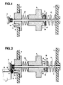
- Figure 1 is a partial sectional view of the can opener according to the invention, illustrating the drive shaft occupying its inactive position
- Figure 2 is a view similar to Figure 1, illustrating the drive shaft occupying its active position.
- the can opener shown in Figures 1 and 2 comprises, in a housing 1, an electric motor (not shown) capable of driving in rotation, by means of at least one toothed wheel 2, a shaft of drive 3, one end of which protrudes transversely to one 4 of the walls 4.5 of the housing 1 and carries a roller 6 comprising a drive zone 7 intended to come into contact with the internal lateral upper region 8 of the bead cover 9 for crimping the cover 10 of a box 11, as well as a cutting wheel 12 which is mounted idly around an axis 13 arranged transversely to the drive shaft 3 and of which a cutting sector 14 projects from said wall 4 practically opposite said drive zone 7 of the caster 6 and is intended to cut out the external lateral region of said bead 9.
- an electric motor (not shown) capable of driving in rotation, by means of at least one toothed wheel 2
- a shaft of drive 3 one end of which protrudes transversely to one 4 of the walls 4.5 of the housing 1 and carries a roller 6 comprising
- the drive shaft 3 is mounted both rotating and axially movable in the housing 1 by means of a bidirectional driving mechanism which consists of a lug 16 integral with the drive shaft 3 and capable of moving along a ramp 17 formed on a transverse face 18 of the toothed wheel 2 and limited by two stops 19,20, as well as a compression spring with flange 21 threaded on the drive shaft 3 and bearing at its ends, on the one hand, on the wall 5 of the housing 1 and, on the other hand, on a flat washer 22 resting on the lug 16 , and intended to keep the lug 16 in contact with the ramp 17.
- a bidirectional driving mechanism which consists of a lug 16 integral with the drive shaft 3 and capable of moving along a ramp 17 formed on a transverse face 18 of the toothed wheel 2 and limited by two stops 19,20, as well as a compression spring with flange 21 threaded on the drive shaft 3 and bearing at its ends, on the one hand, on the wall 5 of the housing 1 and, on the other hand, on a
- washers 23, of the Belleville type are interposed between the toothed wheel 2 and the wall 4 of the housing 1 in a manner known per se.
- the lug 16 can drive the shaft 3 in rotation and in translation so that the drive shaft 3 can occupy, in the direction of rotation of said wheel 2, is an inactive position ( Figure 1) for which the caster 6 is distant from the wheel 12 so as to allow the engagement or disengagement of the bead 9 of the box 11, that is to say an active position (FIG. 2) for which the roller 6 is brought closer to the wheel 12 so as to come into engagement with the bead 9 and allow the cutting of the external lateral region 15 of said bead 9.
- Figure 1 for which the caster 6 is distant from the wheel 12 so as to allow the engagement or disengagement of the bead 9 of the box 11, that is to say an active position (FIG. 2) for which the roller 6 is brought closer to the wheel 12 so as to come into engagement with the bead 9 and allow the cutting of the external lateral region 15 of said bead 9.
- the compression spring 21 is chosen so as to exert a sufficiently large compression force to oppose the rise of the lug 16 along the ramp 17 when the caster 6 rotates in a vacuum, now thus the drive shaft 3 in its inactive position (Figure 1), and weak enough to allow the lug 16 to slip on the washer 22 and thus allow the lug 16 to climb along the ramp 17, when the drive zone 7 of the caster 6 is in contact with the bead 9 of a box 11, thus maintaining the drive shaft 3 in its active position (FIG. 2).
- the user turns on the device before inserting the bead 9 of the box 11 between the wheel 12 and the roller 6.
- the motor drives the toothed wheel 2 in rotation.
- the spring 21 prevents the lug 16 from going up along the ramp 17, and blocks it so that the lug 16 rotates the drive shaft 3 as well as the roller 6.
- the user then inserts the bead 9 of the box 11 between the caster 6 and the wheel 12.
- the friction exerted by the bead 9 on the caster 6 adds to the force exerted by the ramp 17 on the lug 16, which allows the lug 16 to oppose the axial force of the spring 21 and thus to climb along the ramp 17, which has the effect of bringing the drive shaft 3 and the caster 6 into translation towards the wheel 12 and allowing thus the cutting of the bead 9 by the wheel 12.
- the direction of rotation of the motor is reversed in a manner known per se for a short period of time, the wheel 2 rotating in the other direction, l lug 16 descends along the ramp 17 until it comes to rest against the stop 19, the roller 6 is distant from the wheel 12 by translation, thus releasing the bead 9, which allows the user to remove the box 11.
- the user inserts the bead 9 of the box 11 between the wheel 12 and the roller 6 and then starts the device.
- the motor drives the toothed wheel 2 in rotation. Thanks to the friction exerted by the bead 9 on the caster 6 and the force exerted by the ramp 17 on the lug 16, the lug 16 rises along the ramp 17 against the axial force exerted by the spring of compression 21, which brings the shaft 3 into translation in the active position, the lug 16 locking against the stop 20, then drives the shaft 3 in rotation thus allowing the cutting of the bead 9.
- the user acts as in the first case.
Landscapes
- Engineering & Computer Science (AREA)
- Mechanical Engineering (AREA)
- Devices For Opening Bottles Or Cans (AREA)
Description
- L'invention se rapporte aux ouvre-boîtes comprenant, dans un boîtier, un moteur électrique susceptible d'entraîner en rotation, par l'intermédiaire d'au moins une roue dentée, un arbre d'entraînement dont une extrémité fait saillie transversalement à l'une des parois du boîtier et porte une roulette comportant une zone d'entraînement destinée a venir en contact avec le bourrelet de sertissage d'une boîte, ainsi qu'une molette coupante qui est montée folle autour d'un axe disposé transversalement à l'arbre d'entraînement et dont un secteur tranchant fait saillie de ladite paroi pratiquement en regard de ladite zone d'entraînement de la roulette et est destiné à venir découper ledit bourrelet.
- Elle concerne, plus précisément, les ouvre-boîtes dans lesquels l'arbre d'entraînement est monté à la fois rotatif et mobile axialement dans le boîtier au moyen d'un mécanisme entraîneur bidirectionnel qui est constitué d'un ergot solidaire de l'arbre d'entraînement et susceptible de se déplacer le long d'une rampe pratiquée sur une face transversale de la roue dentée et limitée par au moins une butée, ainsi que d'un ressort de compression enfilé sur l'arbre d'entraînement et prenant appui, d'une part, sur le boîtier et, d'autre part, sur une rondelle s'appuyant sur l'ergot, et destiné à maintenir l'ergot en contact avec la rampe, ledit ergot pouvant entraîner l'arbre en rotation et en translation de manière que l'arbre d'entraînement puisse occuper, suivant le sens de rotation de ladite roue, soit une position inactive pour laquelle la roulette est éloignée de la molette de manière à permettre l'engagement ou le désengagement du bourrelet de la boîte, soit une position active pour laquelle la roulette est rapprochée de la molette de manière à venir en prise avec le bourrelet et permettre le découpage dudit bourrelet.
- Les ouvre-boîtes comportant un tel mécanisme entraîneur bidirectionnel sont connus. Avec ce mécanisme, la rotation de la roue dentée fait automatiquement changer l'arbre de position en fonction du sens de rotation. L'inconvénient d'un tel mécanisme est que, lorsque l'utilisateur met en marche le moteur avant d'insérer une boîte, l'arbre d'entraînement passe dans sa position active, l'utilisateur ne pouvant plus alors insérer de boîte entre la roulette et la molette.
- L'invention a pour but de remédier à cet inconvénient et de proposer un ouvre-boîtes électrique dont la conception soit simple et économique, et la mise en oeuvre efficace et aisée pour l'utilisateur.
- Selon l'invention, ledit ressort de compression est choisi de manière à exercer une force de compression suffisamment importante pour s'opposer à la montée de l'ergot le long de la rampe lorsque la roulette tourne dans le vide, maintenant ainsi l'arbre d'entraînement dans sa position inactive, et suffisamment faible pour permettre le patinage de l'ergot sur la rondelle et autoriser ainsi l'ergot à monter le long de la rampe, lorsque la zone d'entraînement de la roulette est en contact avec le bourrelet d'une boîte, maintenant ainsi l'arbre d'entraînement dans sa position active.
- Le mécanisme entraîneur bidirectionnel ainsi réalisé est particulièrement simple et permet à l'utilisateur d'insérer la boîte à tout moment, que la roulette tourne ou non.En effet, au moment où l'utilisateur insère la boîte, dans un premier cas, si la roulette tourne déjà, elle est amenée par translation vers sa position active, et dans un deuxième cas si la roulette ne tourne pas, l'utilisateur met en marche l'appareil pour faire tourner la roulette qui par translation va alors occuper sa position active.
- Les caractéristiques et avantages de l'invention ressortiront d'ailleurs de la description qui va suivre,à titre d'exemple, en référence au dessin annexé dans lequel :
la figure 1 est une vue partielle en coupe de l'ouvre-boîtes selon l'invention, illustrant l'arbre d'entraînement occupant sa position inactive; la figure 2 est une vue analogue à la figure 1, illustrant l'arbre d'entraînement occupant sa position active . - L'ouvre-boîtes représenté sur les figures 1 et 2 comprend, dans un boîtier 1, un moteur électrique (non représenté) susceptible d'entraîner en rotation, par l'intermédiaire d'au moins une roue dentée 2, un arbre d'entraînement 3 dont une extrémité fait saillie transversalement à l'une 4 des parois 4,5 du boîtier 1 et porte une roulette 6 comportant une zone d'entraînement 7 destinée à venir en contact avec la région supérieure latérale interne 8 du couvercle du bourrelet 9 de sertissage du couvercle 10 d'une boîte 11, ainsi qu'une molette coupante 12 qui est montée folle autour d'un axe 13 disposé transversalement à l'arbre d'entraînement 3 et dont un secteur tranchant 14 fait saillie de ladite paroi 4 pratiquement en regard de ladite zone d'entraînement 7 de la roulette 6 et est destiné à venir découper la région latérale externe dudit bourrelet 9.
- L'arbre d'entraînement 3 est monté à la fois rotatif et mobile axialement dans le boîtier 1 au moyen d'un mécanisme entraîneur bidirectionnel qui est constitué d'un ergot 16 solidaire de l'arbre d'entraînement 3 et susceptible de se déplacer le long d'une rampe 17 pratiquée sur une face transversale 18 de la roue dentée 2 et limitée par deux butées 19,20, ainsi que d'un ressort de compression à boudin 21 enfilé sur l'arbre d'entraînement 3 et prenant appui par ses extrémités, d'une part, sur la paroi 5 du boîtier 1 et, d'autre part, sur une rondelle plate 22 s'appuyant sur l'ergot 16, et destiné à maintenir l'ergot 16 en contact avec la rampe 17.
- Entre la roue dentée 2 et la paroi 4 du boîtier 1 sont interposées de manière connue en soi des rondelles 23, du type Belleville.
- L'ergot 16 peut entraîner l'arbre 3 en rotation et en translation de manière que l'arbre d'entraînement 3 puisse occuper, suivant le sens de rotation de ladite roue 2, soit une position inactive (figure 1) pour laquelle la roulette 6 est éloignée de la molette 12 de manière à permettre l'engagement ou le désengagement du bourrelet 9 de la boîte 11, soit une position active (figure 2) pour laquelle la roulette 6 est rapprochée de la molette 12 de manière à venir en prise avec le bourrelet 9 et permettre le découpage de la région latérale externe 15 dudit bourrelet 9.
- Selon l'invention, le ressort de compression 21 est choisi de manière à exercer une force de compression suffisamment importante pour s'opposer à la montée de l'ergot 16 le long de la rampe 17 lorsque la roulette 6 tourne dans le vide, maintenant ainsi l'arbre d'entraînement 3 dans sa position inactive (figure 1), et suffisamment faible pour permettre le patinage de l'ergot 16 sur la rondelle 22 et autoriser ainsi l'ergot 16 à monter le long de la rampe 17, lorsque la zone d'entraînement 7 de la roulette 6 est en contact avec le bourrelet 9 d'une boîte 11, maintenant ainsi l'arbre d'entraînement 3 dans sa position active (figure 2).
- Dans un but de clarté on va récapituler et préciser le fonctionnement du mécanisme décrit ci-dessus, que l'on peut décomposer en deux cas :
- Dans le premier cas, l'utilisateur met en marche l'appareil avant d'insérer le bourrelet 9 de la boîte 11 entre la molette 12 et la roulette 6. Le moteur entraîne la roue dentée 2 en rotation. Le ressort 21 empêche l'ergot 16 de monter le long de la rampe 17, et le bloque de manière que l'ergot 16 entraîne en rotation l'arbre d'entraînement 3 ainsi que la roulette 6. L'utilisateur insère alors le bourrelet 9 de la boîte 11 entre la roulette 6 et la molette 12. La friction exercée par le bourrelet 9 sur la roulette 6 s'ajoute à la force exercée par la rampe 17 sur l'ergot 16, ce qui permet à l'ergot 16 de s'opposer à la force axiale du ressort 21 et ainsi de monter le long de la rampe 17, ce qui a pour effet d'amener en translation l'arbre d'entraînement 3 et la roulette 6 vers la molette 12 et de permettre ainsi le découpage du bourrelet 9 par la molette 12. Quand le découpage est terminé, le sens de rotation du moteur est inversé d'une manière connue en soi pendant un court laps de temps, la roue 2 tournant dans l'autre sens, l'ergot 16 descend le long de la rampe 17 jusqu'à venir s'appuyer contre la butée 19, la roulette 6 est éloignée de la molette 12 par translation, libérant ainsi le bourrelet 9, ce qui permet à l'utilisateur d'ôter la boîte 11.
- Dans le deuxième cas, l'utilisateur insère le bourrelet 9 de la boîte 11 entre la molette 12 et la roulette 6 puis il met en marche l'appareil. Le moteur entraîne la roue dentée 2 en rotation. Grâce à la friction exercée par le bourrelet 9 sur la roulette 6 et la force exercée par la rampe 17 sur l'ergot 16, l'ergot 16 monte le long de la rampe 17 à l'encontre de la force axiale exercée par le ressort de compression 21, ce qui amène par translation l'arbre 3 en position active, l'ergot 16 se bloquant contre la butée 20, entraîne ensuite l'arbre 3 en rotation permettant ainsi le découpage du bourrelet 9. Quand le découpage est terminé, l'utilisateur agit comme dans le premier cas.
Claims (1)
- Ouvre-boîtes comprenant, dans un boîtier (1), un moteur électrique susceptible d'entraîner en rotation, par l'intermédiaire d'au moins une roue dentée (2), un arbre d'entraînement (3) dont une extrémité fait saillie transversalement à l'une (4) des parois (4,5) du boîtier (1) et porte une roulette (6) comportant une zone d'entraînement (7) destinée à venir en contact avec le bourrelet (9) de sertissage d'une boîte (11), ainsi qu'une molette coupante (12) qui est montée folle autour d'un axe (13) disposé transversalement à l'arbre d'entraînement (3) et dont un secteur tranchant (14) fait saillie de ladite paroi (4) pratiquement en regard de ladite zone d'entraînement (7) de la roulette (6) et est destiné à venir découper ledit bourrelet (9), ledit arbre d'entraînement (3) étant monté à la fois rotatif et mobile axialement dans le boîtier (1) au moyen d'un mécanisme entraîneur bidirectionnel constitué d'un ergot (16) solidaire de l'arbre d'entraînement (3) et susceptible de se déplacer le long d'une rampe (17) pratiquée sur une face transversale (18) de la roue dentée (2) et limitée par au moins une butée (19,20), ainsi que d'un ressort de compression (21) enfilé sur l'arbre d'entraînement (3) et prenant appui, d'une part, sur le boîtier (1) et, d'autre part, sur une rondelle (22) s'appuyant sur l'ergot (16), et destiné à maintenir l'ergot (16) en contact avec la rampe (17), ledit ergot (16) pouvant entraîner l'arbre (3) en rotation et en translation de manière que l'arbre d'entraînement (3) puisse occuper, suivant le sens de rotation de ladite roue (2), soit une position inactive pour laquelle la roulette (6) est éloignée de la molette (12) de manière à permettre l'engagement ou le désengagement du bourrelet (9) de la boîte (11), soit une position active pour laquelle la roulette (6) est rapprochée de la molette (12) de manière à venir en prise avec le bourrelet (9) et permettre le découpage dudit bourrelet (9),
caractérisé en ce que, ledit ressort de compression (21) est choisi de manière à exercer une force de compression suffisamment importante pour s'opposer à la montée de l'ergot (16) le long de la rampe (17) lorsque la roulette (6) tourne dans le vide, maintenant ainsi l'arbre d'entraînement (3) dans sa position inactive, et suffisamment faible pour permettre le patinage de l'ergot (16) sur la rondelle (22) et autoriser ainsi l'ergot (16) à monter le long de la rampe (17), lorsque la zone d'entraînement (7) de la roulette (6) est en contact avec le bourrelet (9) d'une boîte (11), maintenant ainsi l'arbre d'entraînement (3) dans sa position active.
Applications Claiming Priority (2)
| Application Number | Priority Date | Filing Date | Title |
|---|---|---|---|
| FR8916043 | 1989-12-05 | ||
| FR8916043A FR2655323B1 (fr) | 1989-12-05 | 1989-12-05 | Ouvre-boites. |
Publications (2)
| Publication Number | Publication Date |
|---|---|
| EP0431517A1 EP0431517A1 (fr) | 1991-06-12 |
| EP0431517B1 true EP0431517B1 (fr) | 1993-09-15 |
Family
ID=9388159
Family Applications (1)
| Application Number | Title | Priority Date | Filing Date |
|---|---|---|---|
| EP19900123098 Expired - Lifetime EP0431517B1 (fr) | 1989-12-05 | 1990-12-03 | Ouvre-boîtes |
Country Status (3)
| Country | Link |
|---|---|
| EP (1) | EP0431517B1 (fr) |
| DE (1) | DE69003359T2 (fr) |
| FR (1) | FR2655323B1 (fr) |
Families Citing this family (2)
| Publication number | Priority date | Publication date | Assignee | Title |
|---|---|---|---|---|
| FR2669912B1 (fr) * | 1990-11-29 | 1993-07-30 | Moulinex Sa | Ouvre-boites. |
| CN219031725U (zh) * | 2022-12-01 | 2023-05-16 | 江门市顶厨电器有限公司 | 一种便携式电动开罐器 |
Family Cites Families (3)
| Publication number | Priority date | Publication date | Assignee | Title |
|---|---|---|---|---|
| US3808917A (en) * | 1971-10-26 | 1974-05-07 | Imp Knife Ass Co Inc | Electric can opener |
| US3781989A (en) * | 1972-06-01 | 1974-01-01 | Westinghouse Electric Corp | Can opener |
| FR2645140B1 (fr) * | 1989-03-28 | 1992-03-20 | Moulinex Sa | Ouvre-boites |
-
1989
- 1989-12-05 FR FR8916043A patent/FR2655323B1/fr not_active Expired - Fee Related
-
1990
- 1990-12-03 DE DE1990603359 patent/DE69003359T2/de not_active Expired - Fee Related
- 1990-12-03 EP EP19900123098 patent/EP0431517B1/fr not_active Expired - Lifetime
Also Published As
| Publication number | Publication date |
|---|---|
| EP0431517A1 (fr) | 1991-06-12 |
| DE69003359T2 (de) | 1994-01-27 |
| DE69003359D1 (de) | 1993-10-21 |
| FR2655323B1 (fr) | 1992-07-24 |
| FR2655323A1 (fr) | 1991-06-07 |
Similar Documents
| Publication | Publication Date | Title |
|---|---|---|
| EP0220092A1 (fr) | Dispositif de commande d'un moyen d'accouplement tel que par exemple un embrayage ou un variateur de vitesse ou un frein ou analogue | |
| FR2661958A1 (fr) | Dispositif formant palier de butee. | |
| EP2454930A1 (fr) | Dispositif de transmission pour engin automoteur et engin automoteur équipé d'une telle transmission | |
| EP0381544B1 (fr) | Embrayage centrifuge destiné à un actionneur de condamnation d'une serrure de porte | |
| EP0487939B1 (fr) | Ouvre-boîtes | |
| EP0321319B1 (fr) | Embrayage centrifuge pour actionneur de condamnation d'une serrure de porte de véhicule automobile | |
| EP0829931A1 (fr) | Contacteur tournant à ruban, en particulier pour véhicules automobiles | |
| FR2482907A1 (fr) | Mecanisme de changement de vitesse, et selle de charge et etrier pour ce mecanisme | |
| EP0431517A1 (fr) | Ouvre-boîtes | |
| EP2433534A1 (fr) | Appareil electroménager de préparation culinaire comportant un récipient renfermant un outil coupant entrainé en rotation par un moteur | |
| FR2699621A1 (fr) | Motoréducteur à accouplement élastique destiné notamment à un lève-vitre de véhicule. | |
| EP0050086B1 (fr) | Contacteur de feu arrière "stop" pour véhicule tel que cyclomoteur ou motocyclette | |
| FR2691515A1 (fr) | Dispositif de commande de frein de parking. | |
| EP3041715A1 (fr) | Antivol pour colonne de direction de vehicule automobile | |
| FR2574483A1 (fr) | Demarreur electrique a deux moteurs | |
| FR2645140A1 (fr) | Ouvre-boites | |
| EP0114549A1 (fr) | Frein à disque | |
| FR2624575A2 (fr) | Embrayage centrifuge pour actionneur de condamnation d'une serrure de porte de vehicule automobile | |
| FR2830574A1 (fr) | Demarreur notamment pour moteur thermique de vehicule automobile du type a lanceur a accouplement | |
| EP3654109B1 (fr) | Pièce d'horlogerie comprenant deux sources d'énergie | |
| FR2830989A1 (fr) | Contacteur electrique tournant et ensemble de direction de vehicule automobile muni de ce contacteur | |
| FR2532983A1 (fr) | Dispositif d'actionnement perfectionne, notamment pour leve-vitre de vehicule | |
| FR2851999A1 (fr) | Dispositif permettant d'ouvrir sans efforts des couvercles de bocaux en verre | |
| CH372557A (fr) | Appareil ascenseur-descenseur individuel | |
| FR3014976A1 (fr) | Embrayage a friction |
Legal Events
| Date | Code | Title | Description |
|---|---|---|---|
| PUAI | Public reference made under article 153(3) epc to a published international application that has entered the european phase |
Free format text: ORIGINAL CODE: 0009012 |
|
| AK | Designated contracting states |
Kind code of ref document: A1 Designated state(s): DE NL |
|
| 17P | Request for examination filed |
Effective date: 19910715 |
|
| 17Q | First examination report despatched |
Effective date: 19930218 |
|
| GRAA | (expected) grant |
Free format text: ORIGINAL CODE: 0009210 |
|
| AK | Designated contracting states |
Kind code of ref document: B1 Designated state(s): DE NL |
|
| REF | Corresponds to: |
Ref document number: 69003359 Country of ref document: DE Date of ref document: 19931021 |
|
| PLBE | No opposition filed within time limit |
Free format text: ORIGINAL CODE: 0009261 |
|
| STAA | Information on the status of an ep patent application or granted ep patent |
Free format text: STATUS: NO OPPOSITION FILED WITHIN TIME LIMIT |
|
| 26N | No opposition filed | ||
| PGFP | Annual fee paid to national office [announced via postgrant information from national office to epo] |
Ref country code: NL Payment date: 20001231 Year of fee payment: 11 |
|
| PGFP | Annual fee paid to national office [announced via postgrant information from national office to epo] |
Ref country code: DE Payment date: 20011227 Year of fee payment: 12 |
|
| PG25 | Lapsed in a contracting state [announced via postgrant information from national office to epo] |
Ref country code: NL Free format text: LAPSE BECAUSE OF NON-PAYMENT OF DUE FEES Effective date: 20020701 |
|
| NLV4 | Nl: lapsed or anulled due to non-payment of the annual fee |
Effective date: 20020701 |
|
| PG25 | Lapsed in a contracting state [announced via postgrant information from national office to epo] |
Ref country code: DE Free format text: LAPSE BECAUSE OF NON-PAYMENT OF DUE FEES Effective date: 20030701 |