EP0431035B1 - Re-entry and reclosure of cable splice case - Google Patents
Re-entry and reclosure of cable splice case Download PDFInfo
- Publication number
- EP0431035B1 EP0431035B1 EP89909791A EP89909791A EP0431035B1 EP 0431035 B1 EP0431035 B1 EP 0431035B1 EP 89909791 A EP89909791 A EP 89909791A EP 89909791 A EP89909791 A EP 89909791A EP 0431035 B1 EP0431035 B1 EP 0431035B1
- Authority
- EP
- European Patent Office
- Prior art keywords
- sleeve
- rails
- splice
- channel
- plug
- Prior art date
- Legal status (The legal status is an assumption and is not a legal conclusion. Google has not performed a legal analysis and makes no representation as to the accuracy of the status listed.)
- Expired - Lifetime
Links
- 239000000853 adhesive Substances 0.000 claims abstract description 20
- 230000001070 adhesive effect Effects 0.000 claims abstract description 20
- 238000000034 method Methods 0.000 claims abstract description 17
- 239000004831 Hot glue Substances 0.000 claims abstract description 7
- 238000010438 heat treatment Methods 0.000 claims abstract description 7
- 238000011084 recovery Methods 0.000 claims description 8
- 238000002844 melting Methods 0.000 claims description 2
- 230000008018 melting Effects 0.000 claims description 2
- 239000003566 sealing material Substances 0.000 description 6
- 239000002131 composite material Substances 0.000 description 5
- 230000007613 environmental effect Effects 0.000 description 5
- 239000000463 material Substances 0.000 description 5
- 239000004744 fabric Substances 0.000 description 4
- 238000009434 installation Methods 0.000 description 4
- 239000011159 matrix material Substances 0.000 description 4
- 239000004020 conductor Substances 0.000 description 3
- 239000011521 glass Substances 0.000 description 3
- 239000002184 metal Substances 0.000 description 3
- 229920000642 polymer Polymers 0.000 description 3
- 238000007789 sealing Methods 0.000 description 3
- 230000004888 barrier function Effects 0.000 description 2
- 230000007797 corrosion Effects 0.000 description 2
- 238000005260 corrosion Methods 0.000 description 2
- 230000004048 modification Effects 0.000 description 2
- 238000012986 modification Methods 0.000 description 2
- 239000004033 plastic Substances 0.000 description 2
- 229920003023 plastic Polymers 0.000 description 2
- 239000004677 Nylon Substances 0.000 description 1
- 239000004952 Polyamide Substances 0.000 description 1
- 230000004913 activation Effects 0.000 description 1
- 238000004026 adhesive bonding Methods 0.000 description 1
- 238000010420 art technique Methods 0.000 description 1
- 230000005540 biological transmission Effects 0.000 description 1
- 239000003086 colorant Substances 0.000 description 1
- 239000000835 fiber Substances 0.000 description 1
- 239000012530 fluid Substances 0.000 description 1
- 239000011888 foil Substances 0.000 description 1
- 239000002654 heat shrinkable material Substances 0.000 description 1
- 229920001903 high density polyethylene Polymers 0.000 description 1
- 239000004700 high-density polyethylene Substances 0.000 description 1
- 229920001684 low density polyethylene Polymers 0.000 description 1
- 239000004702 low-density polyethylene Substances 0.000 description 1
- 239000000155 melt Substances 0.000 description 1
- 229920001778 nylon Polymers 0.000 description 1
- 229920002647 polyamide Polymers 0.000 description 1
- 229920000098 polyolefin Polymers 0.000 description 1
- 230000001681 protective effect Effects 0.000 description 1
- 230000008439 repair process Effects 0.000 description 1
- 239000000565 sealant Substances 0.000 description 1
- 238000000926 separation method Methods 0.000 description 1
- 239000007787 solid Substances 0.000 description 1
- 230000007704 transition Effects 0.000 description 1
- XLYOFNOQVPJJNP-UHFFFAOYSA-N water Substances O XLYOFNOQVPJJNP-UHFFFAOYSA-N 0.000 description 1
Images


Classifications
-
- G—PHYSICS
- G02—OPTICS
- G02B—OPTICAL ELEMENTS, SYSTEMS OR APPARATUS
- G02B6/00—Light guides; Structural details of arrangements comprising light guides and other optical elements, e.g. couplings
- G02B6/44—Mechanical structures for providing tensile strength and external protection for fibres, e.g. optical transmission cables
- G02B6/4439—Auxiliary devices
- G02B6/4471—Terminating devices ; Cable clamps
- G02B6/4476—Terminating devices ; Cable clamps with heat-shrinkable elements
-
- H—ELECTRICITY
- H02—GENERATION; CONVERSION OR DISTRIBUTION OF ELECTRIC POWER
- H02G—INSTALLATION OF ELECTRIC CABLES OR LINES, OR OF COMBINED OPTICAL AND ELECTRIC CABLES OR LINES
- H02G15/00—Cable fittings
- H02G15/08—Cable junctions
- H02G15/18—Cable junctions protected by sleeves, e.g. for communication cable
- H02G15/1806—Heat shrinkable sleeves
- H02G15/1813—Wraparound or slotted sleeves
-
- Y—GENERAL TAGGING OF NEW TECHNOLOGICAL DEVELOPMENTS; GENERAL TAGGING OF CROSS-SECTIONAL TECHNOLOGIES SPANNING OVER SEVERAL SECTIONS OF THE IPC; TECHNICAL SUBJECTS COVERED BY FORMER USPC CROSS-REFERENCE ART COLLECTIONS [XRACs] AND DIGESTS
- Y10—TECHNICAL SUBJECTS COVERED BY FORMER USPC
- Y10S—TECHNICAL SUBJECTS COVERED BY FORMER USPC CROSS-REFERENCE ART COLLECTIONS [XRACs] AND DIGESTS
- Y10S174/00—Electricity: conductors and insulators
- Y10S174/08—Shrinkable tubes
-
- Y—GENERAL TAGGING OF NEW TECHNOLOGICAL DEVELOPMENTS; GENERAL TAGGING OF CROSS-SECTIONAL TECHNOLOGIES SPANNING OVER SEVERAL SECTIONS OF THE IPC; TECHNICAL SUBJECTS COVERED BY FORMER USPC CROSS-REFERENCE ART COLLECTIONS [XRACs] AND DIGESTS
- Y10—TECHNICAL SUBJECTS COVERED BY FORMER USPC
- Y10T—TECHNICAL SUBJECTS COVERED BY FORMER US CLASSIFICATION
- Y10T29/00—Metal working
- Y10T29/49—Method of mechanical manufacture
- Y10T29/49002—Electrical device making
- Y10T29/49117—Conductor or circuit manufacturing
- Y10T29/49194—Assembling elongated conductors, e.g., splicing, etc.
-
- Y—GENERAL TAGGING OF NEW TECHNOLOGICAL DEVELOPMENTS; GENERAL TAGGING OF CROSS-SECTIONAL TECHNOLOGIES SPANNING OVER SEVERAL SECTIONS OF THE IPC; TECHNICAL SUBJECTS COVERED BY FORMER USPC CROSS-REFERENCE ART COLLECTIONS [XRACs] AND DIGESTS
- Y10—TECHNICAL SUBJECTS COVERED BY FORMER USPC
- Y10T—TECHNICAL SUBJECTS COVERED BY FORMER US CLASSIFICATION
- Y10T428/00—Stock material or miscellaneous articles
- Y10T428/13—Hollow or container type article [e.g., tube, vase, etc.]
- Y10T428/1328—Shrinkable or shrunk [e.g., due to heat, solvent, volatile agent, restraint removal, etc.]
- Y10T428/1331—Single layer [continuous layer]
Definitions
- This invention relates to a technique for re-entry and reclosure of a cable splice case, formed from a heat-shrinkable wrap-around sleeve.
- a protective covering known as a splice case has to be built up around the splice and extending from intact cable jacket one side of the splice to intact cable jacket the other side of the splice. In this way the missing cable jacket is made good, providing environmental protection for the otherwise exposed conductors, and the resulting splice case is generally expected to have a lifetime comparable to that of the cables themselves, typically at least twenty years.
- heat-shrinkable plastics materials have been used in the form of sleeves that are positioned around cable splices and shrunk down into engagement with the cables either side of the splice. Heat-shrinkability allows such sleeves to be supplied over-sized, providing easy installation, and afterwards caused tightly to engage the cables, providing excellent environmental sealing, by the simple step of heating, generally by means of a gas torch.
- a liner comprises a central cylindrical part and frusto-contical end pieces and is positioned around a cable splice, the central part overlying the bulky splice itself and the end pieces providing smooth tapers down to the cables either side of the splice.
- a liner may comprise, for example two semi-cylindrical half shells or a sheet of material that is rolled around the splice. In either case, end portions of the liner may comprise tapered fingers (giving ends of the liner the appearance of a crown) which can be bent inwards to provide the frusto-conical end portions.
- the sleeve is shrunk around the liner, giving the resulting splice case the shape of a cylinder with frusto-conical ends.
- a sleeve supplied in tubular form (of closed cross-section) cannot of course be used.
- the solution is to use a wrap-around sleeve, a most successful design of which is disclosed in GB 1155470 (Raychem).
- a sleeve is supplied as a sheet of heat-shrinkable material having upstanding protuberances (known as rails, although no particular shape is implied by the term) at, and generally running continuously along, opposing edge portions of the sheet.
- the sleeve is wrapped around the splice by bringing together opposing rails which are then secured together to maintain the sleeve in the wrapped-around configuration. They may be secured together by, for example, an elongate channel C-shaped in cross-section that is slid over them. The sleeve is then heated to cause it to shrink.
- One of the rails may be positioned a short distance (a few centimetres being typical) from an extreme edge, the portion of sleeve between that rail and that extreme edge being known as a flap. The flap will underlie the two rails when they are brought together on installation of the sleeve, and may form a seal or help in improve sealing between the rails.
- the sleeve may be internally coated with a sealing material to enhance the environmental seal provided.
- a sealing material is heat-activatable, for example in a hot-melt adhesive, such that a single heating step causes shrinkage of the sleeve and activation of the sealing material.
- the known technique is as follows. Firstly, the rails and channel are cut away from the surface of the sleeve. This need not cause the sleeve to open up since an underlying adhesive may secure the sleeve together during its service life; the rails and channel serving to hold the sleeve closed merely during heat installation. A circumferential cut is made through the splice case approximately at each end of the cylindrical portion thereof.
- a longitudinal cut is then made joining the two circumferential cuts, and the portion of sleeve between those two cuts is removed by unwapping it away from the underlying liner. This leaves frusto-conical butts of the old sleeve in place on the cables, from between and within which the liner can be pulled away exposing the splice. In some designs of splice case the liner may come away with the central part of the sleeve.
- the sleeve is preferably not removed in its entirety because the seals between the sleeve and the cables once made are best not disturbed.
- the liner is replaced (or if it was damaged a new liner inserted) and a new sleeve, which may be shorter than the original sleeve, is shrunk over the butts of the old sleeve so that it bridges the gap between them. If this new sleeve is to make an environmental seal to the butts of the old sleeve it was thought necessary that the circumference of the butts be smooth at some position along their length over which the new sleeve will lie; hence removal of the old rails and channel.
- the channel is not able to hold the rails together in such away that there is no gap between them at their base. This is because the channel must be a reasonably easy fit over the rails if friction is not to prevent it being installed, and because the shrinkage forces of the sleeve tend to pull the base of the rails apart from one another. When the rails and channel are cut from the sleeve a groove will therefore be visible between the resulting edges of the sleeve, which will provide a leak path into the reclosed splice case formed by shrinking down the new sleeve.
- Various techniques have been proposed to fill such a groove with adhesive.
- EP 0068705 discloses a shrinkable sleeve of the rail-and-channel type with flap, having at the base of one of the rails (or the flap) means which on recovery of the sleeve allows passage of sealant on a surface of the sleeve into a region between the two rails and the flap.
- EP 0092347 discloses a rail-and-channel type of sleeve having means that provides localized separation between the rails when they are held together by the channel, resulting in localized adhesive bonding of the rails.
- a heat-shrinkable sleeve that is difficult to cut, and that therefore has excellent split resistance, is disclosed in EP0116393 (Raychem). That sleeve comprises a composite structure of a heat-recoverable fabric and a polymer matrix material (to which fibres of the fabric are preferably bonded), wherein:
- Such a composite structure preferably comprises a weave or knit of recoverable cross-linked polyolefin (preferably high density polyethylene) together with a non-recoverable fibre such as glass, embedded in a preferably cross-linked polymeric matrix material, for example low density polyethylene.
- recoverable cross-linked polyolefin preferably high density polyethylene
- non-recoverable fibre such as glass
- the present invention allows reclosure over existing rails by providing a plug comprising a sealing material that can be positioned over the rails, and that is heat-softenable.
- the present invention provides a method of reentering and reclosing a cable splice case enclosing a splice between first and second cables and comprising a wrap-around sleeve having opposing longitudinal edge portions, each bearing a rail, the edge portions having been brought together around the splice such that the rails are adjacent one another and having a closure channel over the adjacent rails, which method comprises:
- a surprisingly good environmental seal can be made in this way.
- the channel may comprise metal and be liable to corrosion, and removal of a portion of it will break any leak or corrosion path.
- the portion of channel that is removed is a portion at the new end that is created by removal of the intermediate portion of the sleeve.
- the channel is preferably elongate and substantially C-shaped in cross-section and the rails preferably have an undercut adjacent the surface of the sleeve. Then, the channel can be slid longitudinally over the rails, but cannot be removed from them in a direction radial with respect to the sleeve. It may be desirable that the channel be flexible (after shrinkage the sleeve will generally adopt the shape of the splice) and to this end it may have transverse slots spaced longitudinally along its back-bone. Thus, its edges that grip the sleeve at the undercut of the rails may be continuous which may aid installation of the channel and avoid damage to the sleeve.
- the channel may comprise two or more (preferably three) parts, the parts optionally being temporarily held together or held aligned by clips.
- the adhesive plug referred to above preferably comprises a hot-melt adhesive, especially one based on a polyamide. It preferably has a crystalline melt temperature from 50°C below to 15°C above the recovery temperature of the reclosure sleeve. A more preferred range is from 40°C below to 10°C above, especially from 40°C below to 5°C above.
- the melt temperature is preferably from 70°C to 130°C, more preferably 80°C to 120°C. Its viscosity at about 160°C is preferably from 20-100 pascal seconds, more preferably from 35-70 pascal seconds.
- the plug is preferably shaped to have a flat or gently curved upper surface (the surface that will face the overlying reclosure sleeve) and a lower surface shaped to receive the rails.
- the lower surface therefore preferably has a recess therein, which recess is preferably blind so that a block of adhesive is provided adjacent the newly cut ends of the rails.
- the plug is preferably a close fit over the rails so that friction can hold it in place during the reclosure operation.
- the reclosure sleeve may, however, be internally coated with a sealing material such as a hot-melt adhesive and this too may be forced out on heating (due to the recovery forces of the sleeve) and as a result it may be difficult to be certain that the plug has properly softened. Extra heat may be needed to soften the plug, due to the greater thermal mass of the plug and due to its being shielded by the overlying sleeve. In order that softening of the plug be separately visible it is preferred that the plug and the sleeve adhesive be of different colours.
- the plug is preferably of a bright colour such as orange or yellow.
- the splice is preferably further protected by a liner, over which the original sleeve and later the reclosure sleeve are installed.
- the liner may comprise a sheet of material such as cardboard, optionally with other layers such as metal foil or plastics film, that is rolled around the splice and has tapered ends. Alternatively it may comprise metal half-shells with integral or separate tapering ends.
- the original sleeve is preferably installed around the sleeve by heat-shrinkage, although non-heat shrinkable sleeves may be used.
- Preferred sleeves are fabric-based composites as described above, preferably comprising a weave of circumferentially-extending recoverable fibres (preferably weft but optionally warp) and longitudinally-extending non recoverable fibres (preferably warp but optionally weft) such as glass.
- the longitudinally-extending fibres may comprise monfilaments or multi-filament bundles, such bundles preferably being blocked by a polymeric material to prevent fluid wicking along the interstices between the filaments. Such wicking could provide a leak path into the reentered and reclosed splice case.
- Subsequent reentries and reclosures may be carried out by methods disclosed above (all or only an intermediate portion of the first reclosure sleeve being removed) but, for example, the whole of the rails and channel of the first reclosure sleeve may be removed. This modification may be preferred in order that the original adhesive plugs be not disturbed.
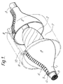
- Figure 1 shows a splice case formed by shrinking a wrap-around sleeve 1 around a cable splice bundle 2 and into engagement with two cables 3 that it joins.
- Opposing longitudinal edge portions of the wraparound sleeve 1 bear upstanding rails 4 which are trapped within a closure channel 5, substantially C-shaped in cross-section.
- the rails are undercut adjacent a surface of the sleeve thus preventing the channel from parting radially from the rails on recovery of the sleeve.
- the channel 5 is provided with transverse slots 6 longitudinally spaced along its "backbone", that is along the left hand side of the letter C as written. These slots provide longitudinal flexibility, ie allow the channel to take up the shape of the splice as shown.
- FIGs 2a,2b and 2c A reentry and reclosure method according to the invention is shown in Figures 2a,2b and 2c.
- Figure 2a an intact original sleeve 1 is shown around a splice ? between cables 3.
- the sleeve 1 is installed around a liner 15 which gives the splice case extra strength, a pleasing shape, and may provide a moisture vapour barrier.
- the sleeve carries a hot-melt adhesive on its inner surface, which is shown dotted.
- Re-entry is achieved by making two circumferential cuts and removing an intermediate portion 7 of the sleeve, as shown in Figure 2b. If a multi-part liner is used, a central portion may come away with the central part of the sleeve; alternatively the entire liner may be pulled out from between and within the remaining end portions 8 of the sleeve.
- a portion of channel 5 is removed from each end portion 8, preferably at the newly created ends, to leave exposed portions 15 of the rails, where adhesive plugs are to be positioned.
- a reclosure sleeve 10 is shown positioned around the splice ready for shrinkage down to form a bridge for one end porton 8 to the other.
- the sleeve 10 can be seen to extend from one adhesive plug to the other, and may of course also extend past the plugs.
- the reclosure sleeve will generally be of the wraparound type, and a closure channel 6 can be seen.
- the liner 15 can be seen to have been reconstructed (or replaced).
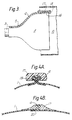
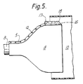
- Figures 3, 4a, 4b,5,6a,6b and 6c show an adhesive plug as used in the invention.
- an end portion of the channel 5 can be seen to be removed to leave a portion 16 of the rails 4 exposed.
- the adhesive plug 17 is shown in part in Figure 3, and may have a central recess as shown in Figure 4A into which the rails 4 are received.
- the plug 17 may have an end part 18 that does not have a recess.
- the recess is shown as 19 in Figure 4a, and its internal dimensins preferably correspond to the external dimensions of the channel 5.
- the rails 4 are formed by folding edge portions of the sleeve along elongate members, such as solid flexible rods for example nylon or glass multifilaments, and optionally causing heat-shrinkage of those edge portions.
- Figure 4b shows the adhesive plug 17 after it has been heat softened and deformed by an overlying shrinking sleeve (not shown) thereby forming a seal between that new sleeve and the original sleeve.
- the rails are formed as integral protrusions from edge portions of the sleeve 1.
- One rail 4 is set back from the extreme edge of the sleeve to define a flap 20 that underlies the bases of the rails to help form a seal between them.
- the flap may however be separate from the sleeve.
- a similar flap or one bonded to the sleeve may be provided in the embodiment of Figure 4a.
- FIGS 5 and 6 show an alternative design of adhesive plug.
- the invetion provides sealing, reentry and reclosure techniques and articles therefore (including a sleeve, a channel, and a sealing material) and that any of the techniques disclosed herein may be used singly or in any combination.
Landscapes
- Physics & Mathematics (AREA)
- General Physics & Mathematics (AREA)
- Optics & Photonics (AREA)
- Cable Accessories (AREA)
- Electric Cable Installation (AREA)
- Knives (AREA)
Priority Applications (1)
| Application Number | Priority Date | Filing Date | Title |
|---|---|---|---|
| AT89909791T ATE100645T1 (de) | 1988-08-15 | 1989-08-15 | Erneuter zugang und verschluss eines kabelspleissgehaeuses. |
Applications Claiming Priority (2)
| Application Number | Priority Date | Filing Date | Title |
|---|---|---|---|
| GB888819354A GB8819354D0 (en) | 1988-08-15 | 1988-08-15 | Re-entry & reclosure of cable splice case |
| GB8819354 | 1988-08-15 |
Publications (2)
| Publication Number | Publication Date |
|---|---|
| EP0431035A1 EP0431035A1 (en) | 1991-06-12 |
| EP0431035B1 true EP0431035B1 (en) | 1994-01-19 |
Family
ID=10642147
Family Applications (1)
| Application Number | Title | Priority Date | Filing Date |
|---|---|---|---|
| EP89909791A Expired - Lifetime EP0431035B1 (en) | 1988-08-15 | 1989-08-15 | Re-entry and reclosure of cable splice case |
Country Status (10)
| Country | Link |
|---|---|
| US (1) | US5215607A (tr) |
| EP (1) | EP0431035B1 (tr) |
| JP (1) | JPH04500149A (tr) |
| CA (1) | CA1334244C (tr) |
| DE (1) | DE68912594T2 (tr) |
| DK (1) | DK168840B1 (tr) |
| GB (1) | GB8819354D0 (tr) |
| NO (1) | NO180177C (tr) |
| TR (1) | TR24075A (tr) |
| WO (1) | WO1990001822A1 (tr) |
Families Citing this family (11)
| Publication number | Priority date | Publication date | Assignee | Title |
|---|---|---|---|---|
| GB8819354D0 (en) * | 1988-08-15 | 1988-09-14 | Raychem Sa Nv | Re-entry & reclosure of cable splice case |
| GB8919977D0 (en) * | 1989-09-04 | 1989-10-18 | Raychem Sa Nv | Environmental seal |
| US6329601B1 (en) | 1996-06-17 | 2001-12-11 | David L. Bulford | Service wire splice housing |
| US5958529A (en) * | 1996-11-20 | 1999-09-28 | Raychem Corporation | Side entry sealing device |
| KR100327740B1 (ko) * | 2000-03-15 | 2002-03-15 | 정영현 | 열수축성 슬리이브의 제조방법 |
| KR20020075126A (ko) * | 2001-03-23 | 2002-10-04 | (주)아세아텔레콤 | 열수축관 봉합부의 고정방법 및 고정수단 |
| US6969804B2 (en) * | 2001-06-27 | 2005-11-29 | Salem-Republic Rubber Company | Connector for securing protection device to cable |
| US8853563B2 (en) | 2010-04-16 | 2014-10-07 | Thomas & Betts International, Llc | Cold shrink assembly |
| US9202612B2 (en) | 2012-09-28 | 2015-12-01 | Thomas & Betts International, Llc | Cold shrink assembly |
| CN106877271B (zh) * | 2017-04-17 | 2019-07-05 | 苏州鼎鑫冷热缩材料有限公司 | 用于冷缩件的内衬体 |
| CN106911109B (zh) * | 2017-04-17 | 2019-07-05 | 苏州鼎鑫冷热缩材料有限公司 | 三角形硅橡胶冷缩管的支撑件 |
Family Cites Families (14)
| Publication number | Priority date | Publication date | Assignee | Title |
|---|---|---|---|---|
| US3455336A (en) * | 1965-11-03 | 1969-07-15 | Raychem Corp | Heat recoverable article and process |
| CA1165418A (en) * | 1980-05-12 | 1984-04-10 | Marc F.L. Moisson | Splicing branching or terminating cables |
| EP0068705B1 (en) * | 1981-06-15 | 1986-11-26 | N.V. Raychem S.A. | Re-enterable closure |
| US4885194A (en) * | 1982-01-21 | 1989-12-05 | Raychem Corporation | Re-enterable closure assembly |
| ATE20795T1 (de) * | 1982-04-08 | 1986-08-15 | Raychem Sa Nv | Umhuellungsverschluss. |
| IN159633B (tr) * | 1983-01-06 | 1987-05-30 | Raychem Corp | |
| ES528709A0 (es) * | 1983-01-06 | 1985-05-16 | Raychem Ltd | Un metodo de encerrar un substrato contorneado y un articulo contractil correspondiente. |
| GB8321020D0 (en) * | 1983-08-04 | 1983-09-07 | Raychem Ltd | Cable joint |
| US4767652A (en) * | 1984-01-10 | 1988-08-30 | Raychem Corporation | Pressure retaining enclosure |
| EP0188777B1 (de) * | 1985-01-16 | 1989-03-15 | Walter Rose GmbH & Co. KG | Kabelmuffe mit einer querschnittlich kreuzförmigen Vorrichtung zum Stützen von in Kabelmuffen einlaufenden Kabelenden |
| FR2582854B1 (fr) * | 1985-05-31 | 1988-03-18 | Morel Atel Electromec | Manchon pour proteger les epissures de cables et procede s'y rapportant |
| GB8604089D0 (en) * | 1986-02-19 | 1986-03-26 | Bowthorpe Hellermann Ltd | Heat-shrinkable article |
| GB2195840A (en) * | 1986-10-02 | 1988-04-13 | Egerton A C Ltd | Plug for retaining and sealing cables |
| GB8819354D0 (en) * | 1988-08-15 | 1988-09-14 | Raychem Sa Nv | Re-entry & reclosure of cable splice case |
-
1988
- 1988-08-15 GB GB888819354A patent/GB8819354D0/en active Pending
-
1989
- 1989-08-14 CA CA000608227A patent/CA1334244C/en not_active Expired - Fee Related
- 1989-08-15 TR TR89/0927A patent/TR24075A/tr unknown
- 1989-08-15 EP EP89909791A patent/EP0431035B1/en not_active Expired - Lifetime
- 1989-08-15 WO PCT/GB1989/000949 patent/WO1990001822A1/en not_active Ceased
- 1989-08-15 DE DE68912594T patent/DE68912594T2/de not_active Expired - Fee Related
- 1989-08-15 US US07/655,406 patent/US5215607A/en not_active Expired - Fee Related
- 1989-08-15 JP JP1509108A patent/JPH04500149A/ja active Pending
-
1991
- 1991-02-11 DK DK022591A patent/DK168840B1/da not_active IP Right Cessation
- 1991-02-14 NO NO910592A patent/NO180177C/no unknown
Also Published As
| Publication number | Publication date |
|---|---|
| US5215607A (en) | 1993-06-01 |
| WO1990001822A1 (en) | 1990-02-22 |
| CA1334244C (en) | 1995-02-07 |
| DK168840B1 (da) | 1994-06-20 |
| NO180177C (no) | 1997-02-26 |
| NO180177B (no) | 1996-11-18 |
| DK22591A (da) | 1991-02-11 |
| EP0431035A1 (en) | 1991-06-12 |
| GB8819354D0 (en) | 1988-09-14 |
| DE68912594T2 (de) | 1994-08-25 |
| DE68912594D1 (de) | 1994-03-03 |
| JPH04500149A (ja) | 1992-01-09 |
| TR24075A (tr) | 1991-03-01 |
| DK22591D0 (da) | 1991-02-11 |
| NO910592D0 (no) | 1991-02-14 |
| NO910592L (no) | 1991-02-14 |
Similar Documents
| Publication | Publication Date | Title |
|---|---|---|
| EP0116391B1 (en) | Method of environmentally protecting a telecommunications cable splice and kit-of-parts for carrying out the method | |
| EP0272364B1 (en) | Method of forming a closure member for a recoverable article | |
| EP0431035B1 (en) | Re-entry and reclosure of cable splice case | |
| US4421945A (en) | Junction assembly | |
| EP0223424B1 (en) | Closure for wraparound sleeve | |
| US4436566A (en) | Re-enterable closure | |
| EP0490941B1 (en) | Environmental seal | |
| US4366011A (en) | Heat-recoverable reinforced enclosure | |
| EP0087227A1 (en) | Wraparound sleeve | |
| US4283239A (en) | Bracing method | |
| CA1195742A (en) | Wraparound closure for electrical conductor | |
| CA1284829C (en) | Indicator for dimensionally recoverable sleeves | |
| EP0057582B1 (en) | Re-enterable closure assembly | |
| AU633864B2 (en) | Splice closures | |
| EP0267028A2 (en) | Closure assembly | |
| EP0296868A2 (en) | Recoverable article | |
| EP0041388A1 (en) | Heat recoverable closure assembly | |
| EP0082010B1 (en) | Support for a closure assembly | |
| EP0036306B1 (en) | Heat-recoverable wraparound closure | |
| WO1991014306A1 (en) | Environmental sealing | |
| EP0148785A2 (en) | Pressure retaining enclosure | |
| AU1745292A (en) | Support member |
Legal Events
| Date | Code | Title | Description |
|---|---|---|---|
| PUAI | Public reference made under article 153(3) epc to a published international application that has entered the european phase |
Free format text: ORIGINAL CODE: 0009012 |
|
| 17P | Request for examination filed |
Effective date: 19910131 |
|
| AK | Designated contracting states |
Kind code of ref document: A1 Designated state(s): AT BE CH DE FR GB IT LI NL SE |
|
| 17Q | First examination report despatched |
Effective date: 19930325 |
|
| GRAA | (expected) grant |
Free format text: ORIGINAL CODE: 0009210 |
|
| AK | Designated contracting states |
Kind code of ref document: B1 Designated state(s): AT BE CH DE FR GB IT LI NL SE |
|
| PG25 | Lapsed in a contracting state [announced via postgrant information from national office to epo] |
Ref country code: IT Free format text: LAPSE BECAUSE OF FAILURE TO SUBMIT A TRANSLATION OF THE DESCRIPTION OR TO PAY THE FEE WITHIN THE PRE;WARNING: LAPSES OF ITALIAN PATENTS WITH EFFECTIVE DATE BEFORE 2007 MAY HAVE OCCURRED AT ANY TIME BEFORE 2007. THE CORRECT EFFECTIVE DATE MAY BE DIFFERENT FROM THE ONE RECORDED.SCRIBED TIME-LIMIT Effective date: 19940119 Ref country code: AT Effective date: 19940119 Ref country code: FR Effective date: 19940119 Ref country code: LI Effective date: 19940119 Ref country code: BE Effective date: 19940119 Ref country code: CH Effective date: 19940119 Ref country code: NL Effective date: 19940119 Ref country code: SE Effective date: 19940119 |
|
| REF | Corresponds to: |
Ref document number: 100645 Country of ref document: AT Date of ref document: 19940215 Kind code of ref document: T |
|
| REF | Corresponds to: |
Ref document number: 68912594 Country of ref document: DE Date of ref document: 19940303 |
|
| REG | Reference to a national code |
Ref country code: CH Ref legal event code: PL |
|
| EN | Fr: translation not filed | ||
| NLV1 | Nl: lapsed or annulled due to failure to fulfill the requirements of art. 29p and 29m of the patents act | ||
| PLBE | No opposition filed within time limit |
Free format text: ORIGINAL CODE: 0009261 |
|
| STAA | Information on the status of an ep patent application or granted ep patent |
Free format text: STATUS: NO OPPOSITION FILED WITHIN TIME LIMIT |
|
| 26N | No opposition filed | ||
| PGFP | Annual fee paid to national office [announced via postgrant information from national office to epo] |
Ref country code: GB Payment date: 19970806 Year of fee payment: 9 |
|
| PGFP | Annual fee paid to national office [announced via postgrant information from national office to epo] |
Ref country code: DE Payment date: 19970822 Year of fee payment: 9 |
|
| PG25 | Lapsed in a contracting state [announced via postgrant information from national office to epo] |
Ref country code: GB Free format text: LAPSE BECAUSE OF NON-PAYMENT OF DUE FEES Effective date: 19980815 |
|
| GBPC | Gb: european patent ceased through non-payment of renewal fee |
Effective date: 19980815 |
|
| PG25 | Lapsed in a contracting state [announced via postgrant information from national office to epo] |
Ref country code: DE Free format text: LAPSE BECAUSE OF NON-PAYMENT OF DUE FEES Effective date: 19990601 |