EP0431009B1 - cutting insert - Google Patents
cutting insert Download PDFInfo
- Publication number
- EP0431009B1 EP0431009B1 EP89909482A EP89909482A EP0431009B1 EP 0431009 B1 EP0431009 B1 EP 0431009B1 EP 89909482 A EP89909482 A EP 89909482A EP 89909482 A EP89909482 A EP 89909482A EP 0431009 B1 EP0431009 B1 EP 0431009B1
- Authority
- EP
- European Patent Office
- Prior art keywords
- insert
- cutting
- insert body
- cutting edge
- bottom wall
- Prior art date
- Legal status (The legal status is an assumption and is not a legal conclusion. Google has not performed a legal analysis and makes no representation as to the accuracy of the status listed.)
- Expired - Lifetime
Links
- 238000005520 cutting process Methods 0.000 title claims abstract description 96
- 239000000463 material Substances 0.000 claims abstract description 25
- 229910003460 diamond Inorganic materials 0.000 claims description 4
- 239000010432 diamond Substances 0.000 claims description 4
- 229910052751 metal Inorganic materials 0.000 abstract description 15
- 239000002184 metal Substances 0.000 abstract description 15
- 230000000717 retained effect Effects 0.000 description 7
- 238000003754 machining Methods 0.000 description 5
- 238000004519 manufacturing process Methods 0.000 description 4
- 238000000034 method Methods 0.000 description 3
- 229910052582 BN Inorganic materials 0.000 description 2
- PZNSFCLAULLKQX-UHFFFAOYSA-N Boron nitride Chemical compound N#B PZNSFCLAULLKQX-UHFFFAOYSA-N 0.000 description 2
- 230000002411 adverse Effects 0.000 description 2
- 229910045601 alloy Inorganic materials 0.000 description 2
- 239000000956 alloy Substances 0.000 description 2
- 230000015572 biosynthetic process Effects 0.000 description 2
- 229910000831 Steel Inorganic materials 0.000 description 1
- 239000003082 abrasive agent Substances 0.000 description 1
- 229910052782 aluminium Inorganic materials 0.000 description 1
- XAGFODPZIPBFFR-UHFFFAOYSA-N aluminium Chemical compound [Al] XAGFODPZIPBFFR-UHFFFAOYSA-N 0.000 description 1
- 238000005219 brazing Methods 0.000 description 1
- 239000011195 cermet Substances 0.000 description 1
- 230000001419 dependent effect Effects 0.000 description 1
- 230000000694 effects Effects 0.000 description 1
- 230000003628 erosive effect Effects 0.000 description 1
- 230000014759 maintenance of location Effects 0.000 description 1
- 230000013011 mating Effects 0.000 description 1
- 150000002739 metals Chemical class 0.000 description 1
- 230000004048 modification Effects 0.000 description 1
- 238000012986 modification Methods 0.000 description 1
- 238000007493 shaping process Methods 0.000 description 1
- 239000010959 steel Substances 0.000 description 1
- 239000000758 substrate Substances 0.000 description 1
- MAKDTFFYCIMFQP-UHFFFAOYSA-N titanium tungsten Chemical compound [Ti].[W] MAKDTFFYCIMFQP-UHFFFAOYSA-N 0.000 description 1
- MTPVUVINMAGMJL-UHFFFAOYSA-N trimethyl(1,1,2,2,2-pentafluoroethyl)silane Chemical compound C[Si](C)(C)C(F)(F)C(F)(F)F MTPVUVINMAGMJL-UHFFFAOYSA-N 0.000 description 1
- WFKWXMTUELFFGS-UHFFFAOYSA-N tungsten Chemical compound [W] WFKWXMTUELFFGS-UHFFFAOYSA-N 0.000 description 1
- 229910052721 tungsten Inorganic materials 0.000 description 1
- 239000010937 tungsten Substances 0.000 description 1
- 239000002699 waste material Substances 0.000 description 1
Images


Classifications
-
- B—PERFORMING OPERATIONS; TRANSPORTING
- B23—MACHINE TOOLS; METAL-WORKING NOT OTHERWISE PROVIDED FOR
- B23B—TURNING; BORING
- B23B27/00—Tools for turning or boring machines; Tools of a similar kind in general; Accessories therefor
- B23B27/04—Cutting-off tools
- B23B27/045—Cutting-off tools with chip-breaking arrangements
-
- B—PERFORMING OPERATIONS; TRANSPORTING
- B23—MACHINE TOOLS; METAL-WORKING NOT OTHERWISE PROVIDED FOR
- B23B—TURNING; BORING
- B23B27/00—Tools for turning or boring machines; Tools of a similar kind in general; Accessories therefor
- B23B27/06—Profile cutting tools, i.e. forming-tools
-
- B—PERFORMING OPERATIONS; TRANSPORTING
- B23—MACHINE TOOLS; METAL-WORKING NOT OTHERWISE PROVIDED FOR
- B23B—TURNING; BORING
- B23B2222/00—Materials of tools or workpieces composed of metals, alloys or metal matrices
- B23B2222/16—Cermet
-
- B—PERFORMING OPERATIONS; TRANSPORTING
- B23—MACHINE TOOLS; METAL-WORKING NOT OTHERWISE PROVIDED FOR
- B23B—TURNING; BORING
- B23B2222/00—Materials of tools or workpieces composed of metals, alloys or metal matrices
- B23B2222/28—Details of hard metal, i.e. cemented carbide
-
- B—PERFORMING OPERATIONS; TRANSPORTING
- B23—MACHINE TOOLS; METAL-WORKING NOT OTHERWISE PROVIDED FOR
- B23B—TURNING; BORING
- B23B2226/00—Materials of tools or workpieces not comprising a metal
- B23B2226/12—Boron nitride
- B23B2226/125—Boron nitride cubic [CBN]
-
- B—PERFORMING OPERATIONS; TRANSPORTING
- B23—MACHINE TOOLS; METAL-WORKING NOT OTHERWISE PROVIDED FOR
- B23B—TURNING; BORING
- B23B2226/00—Materials of tools or workpieces not comprising a metal
- B23B2226/31—Diamond
- B23B2226/315—Diamond polycrystalline [PCD]
-
- B—PERFORMING OPERATIONS; TRANSPORTING
- B23—MACHINE TOOLS; METAL-WORKING NOT OTHERWISE PROVIDED FOR
- B23B—TURNING; BORING
- B23B2265/00—Details of general geometric configurations
- B23B2265/34—Round
-
- Y—GENERAL TAGGING OF NEW TECHNOLOGICAL DEVELOPMENTS; GENERAL TAGGING OF CROSS-SECTIONAL TECHNOLOGIES SPANNING OVER SEVERAL SECTIONS OF THE IPC; TECHNICAL SUBJECTS COVERED BY FORMER USPC CROSS-REFERENCE ART COLLECTIONS [XRACs] AND DIGESTS
- Y10—TECHNICAL SUBJECTS COVERED BY FORMER USPC
- Y10T—TECHNICAL SUBJECTS COVERED BY FORMER US CLASSIFICATION
- Y10T407/00—Cutters, for shaping
- Y10T407/24—Cutters, for shaping with chip breaker, guide or deflector
-
- Y—GENERAL TAGGING OF NEW TECHNOLOGICAL DEVELOPMENTS; GENERAL TAGGING OF CROSS-SECTIONAL TECHNOLOGIES SPANNING OVER SEVERAL SECTIONS OF THE IPC; TECHNICAL SUBJECTS COVERED BY FORMER USPC CROSS-REFERENCE ART COLLECTIONS [XRACs] AND DIGESTS
- Y10—TECHNICAL SUBJECTS COVERED BY FORMER USPC
- Y10T—TECHNICAL SUBJECTS COVERED BY FORMER US CLASSIFICATION
- Y10T407/00—Cutters, for shaping
- Y10T407/25—Cutters, for shaping including cut off tool
-
- Y—GENERAL TAGGING OF NEW TECHNOLOGICAL DEVELOPMENTS; GENERAL TAGGING OF CROSS-SECTIONAL TECHNOLOGIES SPANNING OVER SEVERAL SECTIONS OF THE IPC; TECHNICAL SUBJECTS COVERED BY FORMER USPC CROSS-REFERENCE ART COLLECTIONS [XRACs] AND DIGESTS
- Y10—TECHNICAL SUBJECTS COVERED BY FORMER USPC
- Y10T—TECHNICAL SUBJECTS COVERED BY FORMER US CLASSIFICATION
- Y10T407/00—Cutters, for shaping
- Y10T407/26—Cutters, for shaping comprising cutting edge bonded to tool shank
Definitions
- the invention is directed to a cutting insert according to the preamble of claim 1 (see US-A-3 688 366).
- Cutting inserts are well known and a large percentage of them are of the throw away design. Such inserts are detachably clamped on a holder and then are discarded when they become dull or chipped.
- the inserts must be securely and accurately held in place within an insert holder during the cutting operation. This is especially true when the inserts are employed with numerically controlled machines which depend for accuracy upon an accurately located and firmly supported insert.
- the inserts are of a substantial area, it is possible to fix the insert both accurately and firmly within the pocket of a toolholder by providing the insert with a central hole and the toolholder with a pin-type clamping device. In other cases, such inserts may be held in place by a top clamp. Examples of such holders are found in US-A-3,754,309; 3,399,442 and 3,762,005 and GB-A-1,363,542.
- FIG. 1 Another example of a dedicated toolholder-insert system is marketed by the Greenleaf Corporation of Saegertown, Pennsylvania. This system employs a toolholder with a female "V” shaped seat in which an insert with a corresponding male “V” bottom is retained by a clamp adjustably held in the toolholder.
- Iscar Tools LTD. markets a similar toolholder with a female "V” shaped seat in which an insert with a corresponding male "V” bottom is retained.
- Iscar also a markets a toolholder with an insert-pocket wedge geometry having a female "V” shaped seat on the bottom and a male "V” shaped seat on the top. An insert with corresponding male and female “V” shaped bottom and top portions is passively retained in the pocket. No adjustable clamping arrangement is provided in the Iscar toolholder.
- the main object of metal machining is the shaping of the new work surface.
- Much attention is paid to the formation of the chip during the machining process, even though the chip is a waste product. This is because the consumption of energy occurs mainly in the formation and movement of the chip.
- a chip can turn back into the workpiece and damage the machined finish thereof. This represents a significant problem, for example, in machining aluminum wheels in the automotive industry or when deep grooving, profiling or cutting off any material, including synthetics, that produce a continuous chip.
- the chips can cause excessive wear and/or damage to the clamping arrangement and/or toolholder.
- an essential feature of any metalcutting operation is effective chip control.
- a principal class of chips is the discontinuous chip which has the practical advantage of being easily cleared from the cutting area. While some metals and alloys generate discontinuous chips during cutting operations, many do not. It is therefore very desirable to produce discontinuous chips during a cutting operation, regardless of the metal or alloy of the workpiece.
- chip control is an important consideration in metal cutting operations, it has been a long standing objective in the art of metal cutting to develop improved chip control techniques for use with tools as well as improved designs for the cutting inserts.
- improvements to the cutting insert are various chip control geometries which can be molded into the insert during manufacture. These geometries include various depressions and elevations on the surface of the insert.
- US-A-3 688 366 discloses a cutting tool utilizing a cutting insert having a transverse notch adapted for engagement by a hook shaped nose of a clamp bar.
- US-A-4 201 501 discloses a cutting tool securing an insert having a cavity formed in the upper and front insert surface to receive a diamond or other tip material for machining.
- the invention as defined in appending claim 1 provides a cutting insert with a unique configuration that results in improved chip control and metal cutting capabilities.
- This cutting insert can be used in combination with a tool holder including a clamping arrangement substantially eliminating chip erosion of the clamp elements and chip congestion about the clamping elements.
- An embodiment of the cutting insert comprises an insert body with a first and second mounting end.
- a pair of substantially parallel side walls extend between the first and second ends.
- a bottom wall includes means therein defining a bottom wall notch.
- the bottom wall notch is disposed in the insert body and substantially extends from the first end or cutting end to the second end or mounting end of the insert.
- a top wall of the insert body has a forward section, a middle section and a rearward section.
- the forward section in combination with the first or cutting end includes means defining a cutting edge disposed at a first elevation relative to the bottom wall of the insert body.
- the middle section includes means defining at least in part a top wall notch extending across substantially the entire insert body between the side walls.
- the bottom or trough of the top wall notch portion is disposed at a second elevation relative to the bottom wall.
- the rearward section is disposed at a third elevation relative to the bottom wall. The third elevation is less than the first elevation and greater than the second elevation.
- the top wall forward section of the insert body includes means defining a chipbreaker.
- the means defining the chipbreaker is formed during the manufacture of the insert as an integral portion of the insert body and is disposed at a fourth elevation relative to the bottom wall. This fourth elevation is greater than the first elevation.
- the top wall forward portion means which defines the chipbreaker can further include means defining a slot adapted to receive partially therein an advanced metal cutting material such as, for example, a polycrystalline diamond material or a polycrystalline cubic boron nitride (CBN) material or a material of similar quality.
- an advanced metal cutting material such as, for example, a polycrystalline diamond material or a polycrystalline cubic boron nitride (CBN) material or a material of similar quality.
- CBN cubic boron nitride
- the polycrystalline material is bonded to the top wall forward section of the insert body and the means defining the chipbreaker extends at least partially over the polycrystalline material.
- the polycrystalline material defines a cutting edge and the means defining the chipbreaker may define in part a curvilinear surface.
- a cutting insert with improved chip control features and metal cutting capabilities is isometrically shown in Figure 1 and generally indicated by the reference character 10.
- the insert incorporates a hard cemented carbide substrate and a cutting edge formed from an advanced cutting tool material.
- the insert 10 comprises an insert body 12 having a first end 14 and a second end 16.
- the first end 14 is generally referred to as the cutting end and the second end 16 as the mounting end.
- a pair of substantially parallel walls 18 and 20 extend between the first and second ends.
- the cutting end 14 has a slightly cylindrical shape on whole.
- the cutting edge can be a curvilinear edge which is presented to a workpiece, the cutting edge can be of a geometry appropriate for deep grooving, profiling, parting or cutting operations.
- a bottom wall 22 includes therein means 24 defining a first notch disposed in the insert body 12.
- the notch means 24 extends from the first end 14 to the second end 16 of the insert body.
- the notch 24 defines an inverted V-shaped trough along the bottom wall 22 of the insert body.
- the insert body 12 includes a top wall portion 26 having a forward section 28, a central or middle section 30 and a rearward section 32.
- the forward section 28, in combination with the first end 14 of the insert body, define a cutting edge 34.
- the cutting edge 34 is disposed at a first elevation with respect to the bottom 22 of the insert body.
- the middle section 30 includes means 36 defining at least in part a second notch extending substantially across the insert body from first side 18 to the second side 20.
- the bottom or trough portion of the notch 36 is at a second elevation relative to the bottom wall 22 of the insert body.
- the rearward section 32 of the top wall 26 of the insert body is disposed at a third elevation relative to the bottom wall 22.
- the rearward section 32 is generally planar and perpendicular to the sides 18 and 20 of the insert body.
- the rearward section 32 of the top wall 26 is at a third elevation which is less than the first elevation and greater than the second elevation.
- the insert body itself is manufactured according to techniques well known in the art of metalcutting insert manufacture.
- the insert body is preferably a hard cemented carbide such as tungsten or titanium carbide or tungsten titanium carbide, or a cermet or a sialon material, for example.
- the top wall 26 forward section 28 of the insert body 12 includes means 38 defining a chipbreaker.
- the chipbreaker means is disposed at a fourth elevation relative to the bottom 22 of the insert body, which elevation is greater than the first elevation defined between toe cutting edge 34 and the bottom 22 of the insert body.
- the chipbreaker means 38 further includes means 40 defining a slot therein.
- a polycrystalline diamond material or a polycrystalline cubic boron nitride (CBN) material or a material of similar quality (hereinafter referred to as polycrystalline material) is bonded to the top wall forward section 28 of the insert body.
- the slot 40 of the chipbreaker 38 is dimensioned so as to receive therein the rearward portion of the polycrystalline material which is bonded to the top surface 28 of the insert body.
- This polycrystalline material 42 is manufactured separately from the insert body and later bonded thereto by, for example a brazing technique.
- both the cutting edge 34, defined by the polycrystalline material 42, as well as the chipbreaker means 38, are shown to have curvilinear edges or faces which are presented to a workpiece. It should be appreciated that the specific cutting application for which the insert is to be used dictates the geometry of both the cutting edge 34 and the chipbreaker means 38.
- the rear wall 16 of the insert body 12 can be made so as to have a clearance angle which facilitates mounting of the insert and retention thereof in the toolholder. Additionally, the intersecting edge of the insert body bottom portion 22 side walls 18 and 20 and rear end 16 can be beveled as at 44. This bevel 44 also enhances the ease of mounting and securing the insert within the toolholder.
- a toolholder for use with the insert described above is generally indicated by the reference character 50.
- the toolholder 50 is in the form of a bar-like steel member 52 adapted for being clamped in a tool support of any suitable type.
- the holder means 50 has a first end 54, a second end 56, a top surface 58 and a longitudinal mounting axis shown at 60.
- the first end 54 has a cutting insert receiving pocket 62.
- the receiving pocket has one end wall means 64 and a bottom wall means 66.
- the receiving pocket 62 is open on the other four sides.
- the bottom wall means 66 includes means 68 defining a first engaging means.
- the engaging means 68 extends parallel to the longitudinal mounting axis along substantially the entire bottom wall 66 of the insert pocket 62.
- the engaging means 68 on which the cutting insert 10 is mounted is an inverted V-shaped portion.
- the inverted V-shaped portion, or male V, 68 mates with the female V-shaped portion 24 on the bottom wall 22 of the insert body 12.
- the combined mating means 68 and 24 cooperate to insure axial alignment along the longitudinal mounting axis 60 of the toolholder 50.
- the end wall 64 of the pocket 62 is dimensioned so as to cooperate with the clearance angle of the end wall 16 of the insert body 12.
- the top surface 58 of the holder 50 includes a recess 70 therein.
- the recess 70 is adjacent the insert receiving pocket 62 and is substantially perpendicular to the longitudinal mounting axis 60.
- a clamp element 72 has a pair of dependent legs 74 and 76.
- One of the legs 76 defines a second engaging means which cooperates with the notch 36 in the top wall 26 of the insert body 12.
- the other of the legs 74 is adapted to cooperate with the recess 70 in the top surface 58 of the holder 50.
- Means are provided on the holder 50 to engage the clamp element and urge the clamp element toward the holder means.
- This holding and engaging means comprise a clamp screw 78 which extends through a hole 80 in the clamping element 72 which is between the legs thereof and into a threaded hole 82 in the top surface 58 of the toolholder 50.
- alignment of the insert relative to the toolholder is effected by a combination of the engaging means 68 on the bottom wall of the pocket 62 and the means 24 defining the notch in the bottom wall of the insert body.
- the configuration of the toolholder's insert receiving pocket in combination with the configuration of the insert body results in a stable and repeatable insert location for presentation of the insert's cutting edge to the workpiece. Further, the infinitely variable changes in the resultant forces acting on the cutting insert do not adversely effect the location of the insert's cutting edge during metal cutting operations.
- an alternative embodiment of the invention provides a modification of the cutting insert shown in Figures 1 through 4 wherein the insert does not include the polycrystalline material.
- the insert body is of the configuration described in association with Figures 1 through 5 with the exception that the means 40 defining the slot in which the polycrystalline material is mounted as well as the polycrystalline material are not present.
- the cutting edge is defined by the forward section 28 of the insert body.
- the cutting edge can be a curvilinear edge which is presented to a workpiece as shown in the Figures or, for example, the cutting edge can be of a geometry appropriate for deep grooving, profiling or cutting operations. It should be appreciated that the specific cutting application for which the insert is to be used dictates the geometry of the cutting edge.
- FIG. 6 and 7 a plan view of the toolholder with the alternative embodiment of the cutting insert retained therein is shown in a plan and side view respectively.
- the first end 54 of the toolholder 50 is of a dimension which is significantly less in width than the remainder of the toolholder body.
- the cutting edge of the insert is of a greater width than the width of the insert body and the toolholder pocket 62. This configuration provides clearance between the toolholder and the workpiece when engaged in cutting operations.
- a particularly unique feature of the combined cutting insert and toolholder is the low profile of the clamping element with respect to the cutting edge of the insert.
- the clamp element When used in combination with the chipbreaker design shown in Figures 1 through 4, the clamp element is substantially protected from chips coming from the workpiece. Additionally, the extremely low profile of the clamping element relative to the cutting edge of the insert minimizes, if no substantially eliminating, the adverse consequence of a chip being forced back onto the workpiece by contact with a clamping element. It can be seen that a chip is unhampered as it is removed from the workpiece and can travel rearwardly away from the cutting edge of the insert. Thus chip congestion and chip build up in the clamping area is substantially eliminated.
Landscapes
- Engineering & Computer Science (AREA)
- Mechanical Engineering (AREA)
- Cutting Tools, Boring Holders, And Turrets (AREA)
- Magnetically Actuated Valves (AREA)
- Media Introduction/Drainage Providing Device (AREA)
- Turbine Rotor Nozzle Sealing (AREA)
- Milling Processes (AREA)
Abstract
Description
- The invention is directed to a cutting insert according to the preamble of claim 1 (see US-A-3 688 366).
- Cutting inserts are well known and a large percentage of them are of the throw away design. Such inserts are detachably clamped on a holder and then are discarded when they become dull or chipped.
- The inserts must be securely and accurately held in place within an insert holder during the cutting operation. This is especially true when the inserts are employed with numerically controlled machines which depend for accuracy upon an accurately located and firmly supported insert. When the inserts are of a substantial area, it is possible to fix the insert both accurately and firmly within the pocket of a toolholder by providing the insert with a central hole and the toolholder with a pin-type clamping device. In other cases, such inserts may be held in place by a top clamp. Examples of such holders are found in US-A-3,754,309; 3,399,442 and 3,762,005 and GB-A-1,363,542.
- Several toolholding systems designed to work in cooperation with specific insert configurations are available in the metal cutting industry. One example of such a system is the TOP NOTCH brand toolholder and insert combination which is known from US-A-3,754,309 and which is manufactured and sold by Kennametal Inc.. This style of insert which is characterized by a diagonal notch is retained in a three-sided toolholder pocket by means of a clamp arrangement which engages both the notch in the insert and a diagonal recess in the toolholder body.
- Another example of a dedicated toolholder-insert system is marketed by the Greenleaf Corporation of Saegertown, Pennsylvania. This system employs a toolholder with a female "V" shaped seat in which an insert with a corresponding male "V" bottom is retained by a clamp adjustably held in the toolholder. Iscar Tools LTD., markets a similar toolholder with a female "V" shaped seat in which an insert with a corresponding male "V" bottom is retained. Iscar also a markets a toolholder with an insert-pocket wedge geometry having a female "V" shaped seat on the bottom and a male "V" shaped seat on the top. An insert with corresponding male and female "V" shaped bottom and top portions is passively retained in the pocket. No adjustable clamping arrangement is provided in the Iscar toolholder.
- The main object of metal machining is the shaping of the new work surface. Much attention is paid to the formation of the chip during the machining process, even though the chip is a waste product. This is because the consumption of energy occurs mainly in the formation and movement of the chip. Also, a chip can turn back into the workpiece and damage the machined finish thereof. This represents a significant problem, for example, in machining aluminum wheels in the automotive industry or when deep grooving, profiling or cutting off any material, including synthetics, that produce a continuous chip. Moreover, in certain metal cutting operations it has been found that the chips can cause excessive wear and/or damage to the clamping arrangement and/or toolholder. Thus an essential feature of any metalcutting operation is effective chip control. A principal class of chips is the discontinuous chip which has the practical advantage of being easily cleared from the cutting area. While some metals and alloys generate discontinuous chips during cutting operations, many do not. It is therefore very desirable to produce discontinuous chips during a cutting operation, regardless of the metal or alloy of the workpiece.
- It has been a common practice to place a mechanical chip breaking member between the insert and the clamp securing the insert to the tool in order to provide at least a degree of chip control during the cutting operation. This arrangement presents the obvious drawback of increasing the effective area necessary for metal cutting operations with a given tool.
- Because chip control is an important consideration in metal cutting operations, it has been a long standing objective in the art of metal cutting to develop improved chip control techniques for use with tools as well as improved designs for the cutting inserts. Among the improvements to the cutting insert are various chip control geometries which can be molded into the insert during manufacture. These geometries include various depressions and elevations on the surface of the insert.
- US-A-3 688 366 discloses a cutting tool utilizing a cutting insert having a transverse notch adapted for engagement by a hook shaped nose of a clamp bar.
- US-A-4 201 501 discloses a cutting tool securing an insert having a cavity formed in the upper and front insert surface to receive a diamond or other tip material for machining.
- It is an object of the invention to provide an insert with improved chip control characteristics.
- It is another object of this invention to provide a method of manufacturing an insert incorporating advanced cutting tool materials and having improved chip control.
- It is still another object of this invention to provide an insert with improved metal cutting capabilities when machining, for example, nonferrous and abrasive materials or other materials, including synthetics that produce a continuous chip.
- It is yet another object of this invention to provide an improved chip control insert configured to cooperate with a clamping element of an insert toolholder.
- The invention as defined in appending
claim 1 provides a cutting insert with a unique configuration that results in improved chip control and metal cutting capabilities. This cutting insert can be used in combination with a tool holder including a clamping arrangement substantially eliminating chip erosion of the clamp elements and chip congestion about the clamping elements. - An embodiment of the cutting insert comprises an insert body with a first and second mounting end. A pair of substantially parallel side walls extend between the first and second ends. A bottom wall includes means therein defining a bottom wall notch. The bottom wall notch is disposed in the insert body and substantially extends from the first end or cutting end to the second end or mounting end of the insert. A top wall of the insert body has a forward section, a middle section and a rearward section. The forward section in combination with the first or cutting end includes means defining a cutting edge disposed at a first elevation relative to the bottom wall of the insert body. The middle section includes means defining at least in part a top wall notch extending across substantially the entire insert body between the side walls. The bottom or trough of the top wall notch portion is disposed at a second elevation relative to the bottom wall. The rearward section is disposed at a third elevation relative to the bottom wall. The third elevation is less than the first elevation and greater than the second elevation.
- The top wall forward section of the insert body includes means defining a chipbreaker. The means defining the chipbreaker is formed during the manufacture of the insert as an integral portion of the insert body and is disposed at a fourth elevation relative to the bottom wall. This fourth elevation is greater than the first elevation.
- In one embodiment, the top wall forward portion means which defines the chipbreaker can further include means defining a slot adapted to receive partially therein an advanced metal cutting material such as, for example, a polycrystalline diamond material or a polycrystalline cubic boron nitride (CBN) material or a material of similar quality. The polycrystalline material is bonded to the top wall forward section of the insert body and the means defining the chipbreaker extends at least partially over the polycrystalline material. The polycrystalline material defines a cutting edge and the means defining the chipbreaker may define in part a curvilinear surface.
- The above as well as other features and advantages of embodiments of the invention will become apparent through consideration of the detailed description in connection with the several drawings in which:
- Figure 1 is an isometric view of a cutting insert with chip control features and polycrystalline cutting edge.
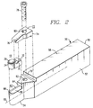
- Figure 2 is an exploded perspective view illustrating a holder and clamping arrangement for use in combination with a cutting insert.
- Figure 3 is a plan view of the cutting insert with chip control features and polycrystalline cutting edge.
- Figure 4 is a side view of the insert with chip control features and polycrystalline cutting edge.
- Figure 5 is a front elevational view of the insert with chip control features and polycrystalline cutting edge.
- Figure 6 is a plan view of the holder with a cutting insert retained therein.
- Figure 7 is a side view of the holder with a cutting insert retained therein.
- A cutting insert with improved chip control features and metal cutting capabilities is isometrically shown in Figure 1 and generally indicated by the
reference character 10. The insert incorporates a hard cemented carbide substrate and a cutting edge formed from an advanced cutting tool material. Theinsert 10 comprises aninsert body 12 having afirst end 14 and asecond end 16. Thefirst end 14 is generally referred to as the cutting end and thesecond end 16 as the mounting end. A pair of substantiallyparallel walls end 14 has a slightly cylindrical shape on whole. However, while the cutting edge can be a curvilinear edge which is presented to a workpiece, the cutting edge can be of a geometry appropriate for deep grooving, profiling, parting or cutting operations. It should be appreciated that the specific cutting application for which the insert is to be used dictates the geometry of the cutting edge and the cuttingend 14 of the insert body. Abottom wall 22 includes therein means 24 defining a first notch disposed in theinsert body 12. The notch means 24 extends from thefirst end 14 to thesecond end 16 of the insert body. Thenotch 24 defines an inverted V-shaped trough along thebottom wall 22 of the insert body. Theinsert body 12 includes atop wall portion 26 having aforward section 28, a central ormiddle section 30 and arearward section 32. Theforward section 28, in combination with thefirst end 14 of the insert body, define acutting edge 34. Thecutting edge 34 is disposed at a first elevation with respect to the bottom 22 of the insert body. Themiddle section 30 includesmeans 36 defining at least in part a second notch extending substantially across the insert body fromfirst side 18 to thesecond side 20. The bottom or trough portion of thenotch 36 is at a second elevation relative to thebottom wall 22 of the insert body. Therearward section 32 of thetop wall 26 of the insert body is disposed at a third elevation relative to thebottom wall 22. Therearward section 32 is generally planar and perpendicular to thesides rearward section 32 of thetop wall 26 is at a third elevation which is less than the first elevation and greater than the second elevation. - The insert body itself is manufactured according to techniques well known in the art of metalcutting insert manufacture. The insert body is preferably a hard cemented carbide such as tungsten or titanium carbide or tungsten titanium carbide, or a cermet or a sialon material, for example.
- In the embodiment of Figures 1 through 5, the
top wall 26forward section 28 of theinsert body 12 includesmeans 38 defining a chipbreaker. The chipbreaker means is disposed at a fourth elevation relative to the bottom 22 of the insert body, which elevation is greater than the first elevation defined betweentoe cutting edge 34 and the bottom 22 of the insert body. The chipbreaker means 38 further includesmeans 40 defining a slot therein. In this embodiment of the insert of this invention, a polycrystalline diamond material or a polycrystalline cubic boron nitride (CBN) material or a material of similar quality (hereinafter referred to as polycrystalline material) is bonded to the top wall forwardsection 28 of the insert body. When used in combination with the chipbreaker as shown, theslot 40 of thechipbreaker 38 is dimensioned so as to receive therein the rearward portion of the polycrystalline material which is bonded to thetop surface 28 of the insert body. Thispolycrystalline material 42 is manufactured separately from the insert body and later bonded thereto by, for example a brazing technique. In Figure 1, both thecutting edge 34, defined by thepolycrystalline material 42, as well as the chipbreaker means 38, are shown to have curvilinear edges or faces which are presented to a workpiece. It should be appreciated that the specific cutting application for which the insert is to be used dictates the geometry of both thecutting edge 34 and the chipbreaker means 38. - The
rear wall 16 of theinsert body 12 can be made so as to have a clearance angle which facilitates mounting of the insert and retention thereof in the toolholder. Additionally, the intersecting edge of the insertbody bottom portion 22side walls rear end 16 can be beveled as at 44. Thisbevel 44 also enhances the ease of mounting and securing the insert within the toolholder. - A toolholder for use with the insert described above is generally indicated by the
reference character 50. Thetoolholder 50 is in the form of a bar-like steel member 52 adapted for being clamped in a tool support of any suitable type. The holder means 50 has afirst end 54, asecond end 56, atop surface 58 and a longitudinal mounting axis shown at 60. Thefirst end 54 has a cutting insert receiving pocket 62. The receiving pocket has one end wall means 64 and a bottom wall means 66. The receiving pocket 62 is open on the other four sides. The bottom wall means 66 includesmeans 68 defining a first engaging means. The engaging means 68 extends parallel to the longitudinal mounting axis along substantially theentire bottom wall 66 of the insert pocket 62. The engaging means 68 on which the cuttinginsert 10 is mounted is an inverted V-shaped portion. The inverted V-shaped portion, or male V, 68 mates with the female V-shapedportion 24 on thebottom wall 22 of theinsert body 12. The combined mating means 68 and 24 cooperate to insure axial alignment along the longitudinal mountingaxis 60 of thetoolholder 50. Theend wall 64 of the pocket 62 is dimensioned so as to cooperate with the clearance angle of theend wall 16 of theinsert body 12. - The
top surface 58 of theholder 50 includes arecess 70 therein. Therecess 70 is adjacent the insert receiving pocket 62 and is substantially perpendicular to the longitudinal mountingaxis 60. - A
clamp element 72 has a pair ofdependent legs legs 76 defines a second engaging means which cooperates with thenotch 36 in thetop wall 26 of theinsert body 12. The other of thelegs 74 is adapted to cooperate with therecess 70 in thetop surface 58 of theholder 50. - Means are provided on the
holder 50 to engage the clamp element and urge the clamp element toward the holder means. This holding and engaging means comprise aclamp screw 78 which extends through ahole 80 in the clampingelement 72 which is between the legs thereof and into a threadedhole 82 in thetop surface 58 of thetoolholder 50. When the insert is placed in the pocket, the clamp member is put in position, and screw 78 is tightened up, and the insert is pressed firmly against thebottom wall 66 of the insert pocket 62 while simultaneously being drawn towardend wall 64. The insert is thus fixedly clamped in the pocket in the holder and is accurately located therein by being urged against the walls of the pocket. As indicated above, alignment of the insert relative to the toolholder is effected by a combination of the engaging means 68 on the bottom wall of the pocket 62 and themeans 24 defining the notch in the bottom wall of the insert body. The configuration of the toolholder's insert receiving pocket in combination with the configuration of the insert body results in a stable and repeatable insert location for presentation of the insert's cutting edge to the workpiece. Further, the infinitely variable changes in the resultant forces acting on the cutting insert do not adversely effect the location of the insert's cutting edge during metal cutting operations. - An alternative embodiment of the invention provides a modification of the cutting insert shown in Figures 1 through 4 wherein the insert does not include the polycrystalline material. In this embodiment which is not illustrated herein, the insert body is of the configuration described in association with Figures 1 through 5 with the exception that the
means 40 defining the slot in which the polycrystalline material is mounted as well as the polycrystalline material are not present. In this embodiment, the cutting edge is defined by theforward section 28 of the insert body. The cutting edge can be a curvilinear edge which is presented to a workpiece as shown in the Figures or, for example, the cutting edge can be of a geometry appropriate for deep grooving, profiling or cutting operations. It should be appreciated that the specific cutting application for which the insert is to be used dictates the geometry of the cutting edge. - Turning now to Figures 6 and 7, a plan view of the toolholder with the alternative embodiment of the cutting insert retained therein is shown in a plan and side view respectively. As can be clearly seen in Figures 6 and 7, the
first end 54 of thetoolholder 50 is of a dimension which is significantly less in width than the remainder of the toolholder body. As can clearly be seen in the plan view, the cutting edge of the insert is of a greater width than the width of the insert body and the toolholder pocket 62. This configuration provides clearance between the toolholder and the workpiece when engaged in cutting operations. A particularly unique feature of the combined cutting insert and toolholder is the low profile of the clamping element with respect to the cutting edge of the insert. When used in combination with the chipbreaker design shown in Figures 1 through 4, the clamp element is substantially protected from chips coming from the workpiece. Additionally, the extremely low profile of the clamping element relative to the cutting edge of the insert minimizes, if no substantially eliminating, the adverse consequence of a chip being forced back onto the workpiece by contact with a clamping element. It can be seen that a chip is unhampered as it is removed from the workpiece and can travel rearwardly away from the cutting edge of the insert. Thus chip congestion and chip build up in the clamping area is substantially eliminated. - It has been found that a metal cutting insert incorporating the features described herein when used in combination with the toolholder provided therefor renders significantly improved chip control over a wide variety of metalcutting conditions. What has been described is an improved cutting insert and toolholder clamping arrangement for use therewith.
Claims (4)
- A cutting insert with an insert body (12) having a first end (14) and a second mounting end (16), a pair of parallel side walls (18, 20) extending between said first and second ends (14, 16), a bottom wall (22) and a top wall (26) having a forward section (28), a middle section (30) and a rearward section (32), said forward section (28) in combination with said first end (14) including means defining a cutting edge (34) disposed at a first elevation relative to said bottom wall (22), said middle section including means (36) defining at least in part a top wall notch (36) extending thereacross and with the bottom portion of said top wall notch being disposed at a second elevation relative to said bottom wall (22), and said rearward section (32) being disposed at a third elevation relative to said bottom wall, which third elevation is less than said first and greater than said second elevations, characterized in that said bottom wall (22) includes means (24) defining a bottom wall notch disposed in said insert body (12) and extending from said first end (14) to said second end (16) so as to be perpendicular to said top wall notch (36), and in that said top wall forward section (28) of said insert body (12) includes means (38) defining a chipbreaker disposed at a fourth elevation relative to the bottom wall (22), which fourth elevation is greater than said first elevation.
- A cutting insert according to claim 1 wherein the means defining the cutting edge (34) defines a curvilinear cutting edge.
- A cutting insert according to claim 1 wherein the means defining the cutting edge (34) comprises a polycrystalline diamond material which is bonded to the top wall forward section (28) of the insert body (12).
- A cutting insert according to anyone of the preceding claims, wherein a tool holder (52) is associated with said cutting insert (10) and adapted to retain said cutting insert (10) therein by means of insert retaining means
Applications Claiming Priority (3)
| Application Number | Priority Date | Filing Date | Title |
|---|---|---|---|
| US07/231,792 US4946319A (en) | 1988-08-12 | 1988-08-12 | Cutting insert and clamping arrangement therefor |
| PCT/US1989/003356 WO1990001386A1 (en) | 1988-08-12 | 1989-08-03 | Cutting insert and clamping arrangement therefor |
| US231792 | 1994-04-25 |
Publications (3)
| Publication Number | Publication Date |
|---|---|
| EP0431009A1 EP0431009A1 (en) | 1991-06-12 |
| EP0431009A4 EP0431009A4 (en) | 1991-08-14 |
| EP0431009B1 true EP0431009B1 (en) | 1994-05-25 |
Family
ID=22870664
Family Applications (1)
| Application Number | Title | Priority Date | Filing Date |
|---|---|---|---|
| EP89909482A Expired - Lifetime EP0431009B1 (en) | 1988-08-12 | 1989-08-03 | cutting insert |
Country Status (7)
| Country | Link |
|---|---|
| US (1) | US4946319A (en) |
| EP (1) | EP0431009B1 (en) |
| JP (1) | JP2774972B2 (en) |
| AT (1) | ATE106028T1 (en) |
| CA (1) | CA1314158C (en) |
| DE (1) | DE68915546T2 (en) |
| WO (1) | WO1990001386A1 (en) |
Cited By (3)
| Publication number | Priority date | Publication date | Assignee | Title |
|---|---|---|---|---|
| WO2003018241A1 (en) * | 2001-08-28 | 2003-03-06 | Kennametal Inc. | Cutting insert and use thereof |
| EP4674547A1 (en) * | 2024-07-01 | 2026-01-07 | Tungaloy Corporation | Cutting tool |
| EP4674548A1 (en) * | 2024-07-01 | 2026-01-07 | Tungaloy Corporation | Cutting tool |
Families Citing this family (26)
| Publication number | Priority date | Publication date | Assignee | Title |
|---|---|---|---|---|
| USD329858S (en) | 1989-03-14 | 1992-09-29 | Sandvik Ab | Cutoff insert |
| USD330901S (en) | 1989-03-14 | 1992-11-10 | Sandvik Ab | Cutoff insert |
| USD330033S (en) | 1989-10-10 | 1992-10-06 | Sandvik Ab | Cutoff insert |
| USD329859S (en) | 1989-10-10 | 1992-09-29 | Sandvik Ab | Cutoff insert |
| USD329439S (en) | 1989-10-10 | 1992-09-15 | Sandvik Ab | Cutoff insert |
| USD329440S (en) | 1989-10-10 | 1992-09-15 | Sandvik Ab | Cutoff insert |
| SE466689B (en) * | 1990-07-19 | 1992-03-23 | Sandvik Ab | CUTS FOR PROFILE AND SAVINGS WARNING |
| IL100703A (en) * | 1992-01-20 | 1995-01-24 | Iscar Ltd | Cutting insert having a circular cutting edge with a chip former |
| JP2000246512A (en) * | 1998-12-28 | 2000-09-12 | Ngk Spark Plug Co Ltd | Diamond coated cutting tools |
| CA2686678C (en) | 2002-01-17 | 2013-05-28 | Iggesund Tools Ab | Method for the simultaneous sharpening of opposed cutting edges |
| US6796752B2 (en) | 2002-06-19 | 2004-09-28 | Manchester Tool Company | Cutting insert |
| US7416372B2 (en) * | 2002-09-03 | 2008-08-26 | Kennametal Inc. | Toolholder |
| WO2007091321A1 (en) * | 2006-02-08 | 2007-08-16 | Koganei Corporation | Processing tool and processing method |
| IL178377A (en) * | 2006-09-28 | 2010-06-30 | Iscar Ltd | Cutting tool having cutting insert secured by non-penetrating abutment of a threaded fastener |
| US9492873B2 (en) | 2011-12-15 | 2016-11-15 | Tungaloy Corporation | Clamp mechanism of cutting insert, cutting tool, cutting insert, and clamp member |
| US10213850B2 (en) * | 2013-04-25 | 2019-02-26 | Kennametal Inc. | Cutting insert, a cutting insert holder, a system including the cutting insert and cutting insert holder, and a method of manufacturing thereof |
| AT13995U1 (en) * | 2013-05-27 | 2015-02-15 | Ceratizit Austria Gmbh | Cutting insert made of carbide or cermet for turning |
| JP2014240100A (en) * | 2013-06-11 | 2014-12-25 | 株式会社ディスコ | Cutting tool |
| US9511421B2 (en) * | 2013-06-14 | 2016-12-06 | Kennametal Inc. | Cutting tool assembly having clamp assembly comprising a clamp and a coolant plate |
| DE102013114124A1 (en) | 2013-12-16 | 2015-06-18 | Hegenscheidt-Mfd Gmbh & Co. Kg | Cutting insert for profile turning and cassette for holding a cutting insert |
| DE102014207507B4 (en) | 2014-04-17 | 2021-12-16 | Kennametal Inc. | Cutting tool and method for producing a cutting tool |
| DE102014207510B4 (en) | 2014-04-17 | 2021-12-16 | Kennametal Inc. | Cutting tool and method for producing a cutting tool |
| US9643282B2 (en) | 2014-10-17 | 2017-05-09 | Kennametal Inc. | Micro end mill and method of manufacturing same |
| US9999927B2 (en) * | 2015-11-30 | 2018-06-19 | Iscar, Ltd. | Parting-off tool assembly with single-cutting-edged solid cutting insert and rigid-insert-seat tool |
| US10010942B2 (en) * | 2016-06-20 | 2018-07-03 | Iscar, Ltd. | Cutting tool and cutting insert having a deep blind opening |
| CN107234257A (en) * | 2017-06-16 | 2017-10-10 | 宁波大学 | A kind of chip breaking device of adjustable circular superhard lathe tool |
Family Cites Families (22)
| Publication number | Priority date | Publication date | Assignee | Title |
|---|---|---|---|---|
| US1700610A (en) * | 1926-07-08 | 1929-01-29 | Bernard H Drees | Tool holder and tool |
| US2713714A (en) * | 1952-11-14 | 1955-07-26 | Wheeling Machine Products Comp | Cut-off tool bits |
| SE305791B (en) * | 1964-02-06 | 1968-11-04 | Diadur Ab | |
| US3399442A (en) * | 1966-09-08 | 1968-09-03 | Kennametal Inc | Cutting insert |
| US3654681A (en) * | 1970-04-22 | 1972-04-11 | Warner Swasey Co | Cutoff tool having improved chip relieving surface |
| US3688366A (en) * | 1970-07-13 | 1972-09-05 | Kennametal Inc | Tool |
| US3762005A (en) * | 1970-08-28 | 1973-10-02 | Ingersoll Milling Machine Co | Indexable cutting insert |
| NO135738C (en) * | 1971-05-28 | 1977-05-25 | Sandvik Ab | |
| US3754309A (en) * | 1972-01-28 | 1973-08-28 | Kennametal Inc | Cutting insert and clamping arrangement therefor |
| US3911543A (en) * | 1974-08-01 | 1975-10-14 | Kennametal Inc | Cutting insert and holder |
| US3934320A (en) * | 1974-11-01 | 1976-01-27 | Kennametal Inc. | Grooving and cut off tool |
| JPS5847404B2 (en) * | 1976-03-30 | 1983-10-22 | 松下電工株式会社 | Manufacturing method of high dielectric constant polymer |
| DE2639245C2 (en) * | 1976-09-01 | 1982-04-08 | Eduard J. Ing.(grad.) 2070 Ahrensberg Job | Fire extinguisher head for automatic fire extinguishing systems |
| US4201501A (en) * | 1977-06-27 | 1980-05-06 | Day Flory M | Cutting tool |
| US4195956A (en) * | 1978-08-01 | 1980-04-01 | Wlajko Mihic | Slotting tool with exchangeable cutting insert |
| US4561810A (en) * | 1981-12-16 | 1985-12-31 | General Electric Company | Bi-level cutting insert |
| NL8204473A (en) * | 1982-11-18 | 1984-06-18 | Comato Bv | CHISEL HOLDER WITH CHISEL. |
| JPS6026883U (en) * | 1983-07-29 | 1985-02-23 | 株式会社パイロット | writing utensil pen core |
| SE441247B (en) * | 1984-02-20 | 1985-09-23 | Seco Tools Ab | SPANISH PROCESSING TOOLS, PREFERRED TO STICKSTAL TOOLS TO SPANISH PROCESSING, PREFERRED TO STICKSTAL |
| SE452273B (en) * | 1986-05-07 | 1987-11-23 | Seco Tools Ab | HAPPENING FOR CUT OFF |
| JPS6314961U (en) * | 1986-05-19 | 1988-01-30 | ||
| DE4032131A1 (en) * | 1990-10-10 | 1992-04-16 | Bosch Gmbh Robert | HIGH VOLTAGE SWITCH |
-
1988
- 1988-08-12 US US07/231,792 patent/US4946319A/en not_active Expired - Lifetime
-
1989
- 1989-08-03 AT AT89909482T patent/ATE106028T1/en not_active IP Right Cessation
- 1989-08-03 DE DE68915546T patent/DE68915546T2/en not_active Expired - Fee Related
- 1989-08-03 EP EP89909482A patent/EP0431009B1/en not_active Expired - Lifetime
- 1989-08-03 WO PCT/US1989/003356 patent/WO1990001386A1/en not_active Ceased
- 1989-08-03 JP JP1508820A patent/JP2774972B2/en not_active Expired - Lifetime
- 1989-08-11 CA CA000608063A patent/CA1314158C/en not_active Expired - Fee Related
Cited By (5)
| Publication number | Priority date | Publication date | Assignee | Title |
|---|---|---|---|---|
| WO2003018241A1 (en) * | 2001-08-28 | 2003-03-06 | Kennametal Inc. | Cutting insert and use thereof |
| US7313991B2 (en) | 2001-08-28 | 2008-01-01 | Kennametal Inc. | Cutting insert and use thereof |
| DE10297038B4 (en) * | 2001-08-28 | 2008-11-27 | Kennametal Inc. | Cutting insert and its use |
| EP4674547A1 (en) * | 2024-07-01 | 2026-01-07 | Tungaloy Corporation | Cutting tool |
| EP4674548A1 (en) * | 2024-07-01 | 2026-01-07 | Tungaloy Corporation | Cutting tool |
Also Published As
| Publication number | Publication date |
|---|---|
| JP2774972B2 (en) | 1998-07-09 |
| US4946319A (en) | 1990-08-07 |
| DE68915546T2 (en) | 1994-09-01 |
| EP0431009A4 (en) | 1991-08-14 |
| ATE106028T1 (en) | 1994-06-15 |
| DE68915546D1 (en) | 1994-06-30 |
| EP0431009A1 (en) | 1991-06-12 |
| WO1990001386A1 (en) | 1990-02-22 |
| JPH03505428A (en) | 1991-11-28 |
| CA1314158C (en) | 1993-03-09 |
Similar Documents
| Publication | Publication Date | Title |
|---|---|---|
| US4946319A (en) | Cutting insert and clamping arrangement therefor | |
| US5100269A (en) | Cutting insert and clamping arrangement therefor | |
| US5032050A (en) | On-edge cutting insert with chip control | |
| EP0821627B1 (en) | Cutting insert with chip control | |
| EP0380541B1 (en) | Cutting insert with chip control | |
| US4854784A (en) | Diamond tipped chip control insert | |
| CA2744524C (en) | Ball nose end mill and insert | |
| US4957396A (en) | Cutting insert with chip control | |
| KR101273128B1 (en) | Cutting tool and cutting insert therefor | |
| EP3600734B1 (en) | Blade-shaped cutting insert and cutting tool therefor | |
| US4588332A (en) | Self-sharpening tool constructions having chip-grooves | |
| US4993893A (en) | Cutting insert with chip control | |
| US4963060A (en) | Cutting insert with chip control | |
| US5088862A (en) | Cutting insert with chip control | |
| CA1322877C (en) | Cutting insert and clamping arrangement therefor | |
| US4011050A (en) | Cutting-off tool | |
| US5037249A (en) | Cutting insert with chip control |
Legal Events
| Date | Code | Title | Description |
|---|---|---|---|
| PUAI | Public reference made under article 153(3) epc to a published international application that has entered the european phase |
Free format text: ORIGINAL CODE: 0009012 |
|
| 17P | Request for examination filed |
Effective date: 19910208 |
|
| AK | Designated contracting states |
Kind code of ref document: A1 Designated state(s): AT BE CH DE FR GB IT LI LU NL SE |
|
| A4 | Supplementary search report drawn up and despatched |
Effective date: 19910626 |
|
| AK | Designated contracting states |
Kind code of ref document: A4 Designated state(s): AT BE CH DE FR GB IT LI LU NL SE |
|
| ITCL | It: translation for ep claims filed |
Representative=s name: DR. ING. A. RACHELI & C. |
|
| EL | Fr: translation of claims filed | ||
| TCAT | At: translation of patent claims filed | ||
| TCNL | Nl: translation of patent claims filed | ||
| DET | De: translation of patent claims | ||
| 17Q | First examination report despatched |
Effective date: 19920302 |
|
| GRAA | (expected) grant |
Free format text: ORIGINAL CODE: 0009210 |
|
| AK | Designated contracting states |
Kind code of ref document: B1 Designated state(s): AT BE CH DE FR GB IT LI LU NL SE |
|
| PG25 | Lapsed in a contracting state [announced via postgrant information from national office to epo] |
Ref country code: LI Effective date: 19940525 Ref country code: CH Effective date: 19940525 Ref country code: AT Effective date: 19940525 |
|
| REF | Corresponds to: |
Ref document number: 106028 Country of ref document: AT Date of ref document: 19940615 Kind code of ref document: T |
|
| REF | Corresponds to: |
Ref document number: 68915546 Country of ref document: DE Date of ref document: 19940630 |
|
| ET | Fr: translation filed | ||
| ITF | It: translation for a ep patent filed | ||
| REG | Reference to a national code |
Ref country code: CH Ref legal event code: PL |
|
| EPTA | Lu: last paid annual fee | ||
| EAL | Se: european patent in force in sweden |
Ref document number: 89909482.5 |
|
| PLBE | No opposition filed within time limit |
Free format text: ORIGINAL CODE: 0009261 |
|
| STAA | Information on the status of an ep patent application or granted ep patent |
Free format text: STATUS: NO OPPOSITION FILED WITHIN TIME LIMIT |
|
| 26N | No opposition filed | ||
| PGFP | Annual fee paid to national office [announced via postgrant information from national office to epo] |
Ref country code: LU Payment date: 19960801 Year of fee payment: 8 |
|
| PG25 | Lapsed in a contracting state [announced via postgrant information from national office to epo] |
Ref country code: LU Free format text: LAPSE BECAUSE OF NON-PAYMENT OF DUE FEES Effective date: 19970803 |
|
| PGFP | Annual fee paid to national office [announced via postgrant information from national office to epo] |
Ref country code: NL Payment date: 19990630 Year of fee payment: 11 |
|
| PGFP | Annual fee paid to national office [announced via postgrant information from national office to epo] |
Ref country code: GB Payment date: 19990702 Year of fee payment: 11 |
|
| PGFP | Annual fee paid to national office [announced via postgrant information from national office to epo] |
Ref country code: SE Payment date: 19990802 Year of fee payment: 11 Ref country code: FR Payment date: 19990802 Year of fee payment: 11 |
|
| PGFP | Annual fee paid to national office [announced via postgrant information from national office to epo] |
Ref country code: BE Payment date: 19990914 Year of fee payment: 11 |
|
| PG25 | Lapsed in a contracting state [announced via postgrant information from national office to epo] |
Ref country code: GB Free format text: LAPSE BECAUSE OF NON-PAYMENT OF DUE FEES Effective date: 20000803 |
|
| PG25 | Lapsed in a contracting state [announced via postgrant information from national office to epo] |
Ref country code: SE Free format text: LAPSE BECAUSE OF NON-PAYMENT OF DUE FEES Effective date: 20000804 |
|
| PG25 | Lapsed in a contracting state [announced via postgrant information from national office to epo] |
Ref country code: BE Free format text: LAPSE BECAUSE OF NON-PAYMENT OF DUE FEES Effective date: 20000831 |
|
| BERE | Be: lapsed |
Owner name: KENNAMETAL INC. Effective date: 20000831 |
|
| PG25 | Lapsed in a contracting state [announced via postgrant information from national office to epo] |
Ref country code: NL Free format text: LAPSE BECAUSE OF NON-PAYMENT OF DUE FEES Effective date: 20010301 |
|
| GBPC | Gb: european patent ceased through non-payment of renewal fee |
Effective date: 20000803 |
|
| EUG | Se: european patent has lapsed |
Ref document number: 89909482.5 |
|
| PG25 | Lapsed in a contracting state [announced via postgrant information from national office to epo] |
Ref country code: FR Free format text: LAPSE BECAUSE OF NON-PAYMENT OF DUE FEES Effective date: 20010430 |
|
| NLV4 | Nl: lapsed or anulled due to non-payment of the annual fee |
Effective date: 20010301 |
|
| REG | Reference to a national code |
Ref country code: FR Ref legal event code: ST |
|
| PGFP | Annual fee paid to national office [announced via postgrant information from national office to epo] |
Ref country code: DE Payment date: 20040831 Year of fee payment: 16 |
|
| PG25 | Lapsed in a contracting state [announced via postgrant information from national office to epo] |
Ref country code: IT Free format text: LAPSE BECAUSE OF NON-PAYMENT OF DUE FEES;WARNING: LAPSES OF ITALIAN PATENTS WITH EFFECTIVE DATE BEFORE 2007 MAY HAVE OCCURRED AT ANY TIME BEFORE 2007. THE CORRECT EFFECTIVE DATE MAY BE DIFFERENT FROM THE ONE RECORDED. Effective date: 20050803 |
|
| PG25 | Lapsed in a contracting state [announced via postgrant information from national office to epo] |
Ref country code: DE Free format text: LAPSE BECAUSE OF NON-PAYMENT OF DUE FEES Effective date: 20060301 |