EP0430183A2 - Fiber type light wave-length converting apparatus - Google Patents
Fiber type light wave-length converting apparatus Download PDFInfo
- Publication number
- EP0430183A2 EP0430183A2 EP19900122674 EP90122674A EP0430183A2 EP 0430183 A2 EP0430183 A2 EP 0430183A2 EP 19900122674 EP19900122674 EP 19900122674 EP 90122674 A EP90122674 A EP 90122674A EP 0430183 A2 EP0430183 A2 EP 0430183A2
- Authority
- EP
- European Patent Office
- Prior art keywords
- light
- wave
- fiber type
- light wave
- length
- Prior art date
- Legal status (The legal status is an assumption and is not a legal conclusion. Google has not performed a legal analysis and makes no representation as to the accuracy of the status listed.)
- Withdrawn
Links
Images

Classifications
-
- G—PHYSICS
- G11—INFORMATION STORAGE
- G11B—INFORMATION STORAGE BASED ON RELATIVE MOVEMENT BETWEEN RECORD CARRIER AND TRANSDUCER
- G11B7/00—Recording or reproducing by optical means, e.g. recording using a thermal beam of optical radiation by modifying optical properties or the physical structure, reproducing using an optical beam at lower power by sensing optical properties; Record carriers therefor
- G11B7/12—Heads, e.g. forming of the optical beam spot or modulation of the optical beam
- G11B7/135—Means for guiding the beam from the source to the record carrier or from the record carrier to the detector
- G11B7/1398—Means for shaping the cross-section of the beam, e.g. into circular or elliptical cross-section
-
- G—PHYSICS
- G02—OPTICS
- G02B—OPTICAL ELEMENTS, SYSTEMS OR APPARATUS
- G02B5/00—Optical elements other than lenses
- G02B5/001—Axicons, waxicons, reflaxicons
-
- G—PHYSICS
- G02—OPTICS
- G02F—OPTICAL DEVICES OR ARRANGEMENTS FOR THE CONTROL OF LIGHT BY MODIFICATION OF THE OPTICAL PROPERTIES OF THE MEDIA OF THE ELEMENTS INVOLVED THEREIN; NON-LINEAR OPTICS; FREQUENCY-CHANGING OF LIGHT; OPTICAL LOGIC ELEMENTS; OPTICAL ANALOGUE/DIGITAL CONVERTERS
- G02F1/00—Devices or arrangements for the control of the intensity, colour, phase, polarisation or direction of light arriving from an independent light source, e.g. switching, gating or modulating; Non-linear optics
- G02F1/35—Non-linear optics
- G02F1/37—Non-linear optics for second-harmonic generation
- G02F1/377—Non-linear optics for second-harmonic generation in an optical waveguide structure
- G02F1/383—Non-linear optics for second-harmonic generation in an optical waveguide structure of the optical fibre type
-
- G—PHYSICS
- G11—INFORMATION STORAGE
- G11B—INFORMATION STORAGE BASED ON RELATIVE MOVEMENT BETWEEN RECORD CARRIER AND TRANSDUCER
- G11B7/00—Recording or reproducing by optical means, e.g. recording using a thermal beam of optical radiation by modifying optical properties or the physical structure, reproducing using an optical beam at lower power by sensing optical properties; Record carriers therefor
- G11B7/12—Heads, e.g. forming of the optical beam spot or modulation of the optical beam
- G11B7/135—Means for guiding the beam from the source to the record carrier or from the record carrier to the detector
- G11B7/1372—Lenses
- G11B7/1376—Collimator lenses
-
- G—PHYSICS
- G02—OPTICS
- G02F—OPTICAL DEVICES OR ARRANGEMENTS FOR THE CONTROL OF LIGHT BY MODIFICATION OF THE OPTICAL PROPERTIES OF THE MEDIA OF THE ELEMENTS INVOLVED THEREIN; NON-LINEAR OPTICS; FREQUENCY-CHANGING OF LIGHT; OPTICAL LOGIC ELEMENTS; OPTICAL ANALOGUE/DIGITAL CONVERTERS
- G02F1/00—Devices or arrangements for the control of the intensity, colour, phase, polarisation or direction of light arriving from an independent light source, e.g. switching, gating or modulating; Non-linear optics
- G02F1/35—Non-linear optics
- G02F1/37—Non-linear optics for second-harmonic generation
- G02F1/372—Means for homogenizing the output beam
Definitions
- the present invention relates to a light wave-length converting apparatus of fiber type.
- a fiber type SHG (Second Harmonics Generator) using a secondary nonlinear optical effect has been known as a light wave-length converting apparatus.
- the fiber type SHG uses the phase matching of Cerenkov irradiation system. According to such a system, the second harmonic (hereinafter, abbreviated to an SH wave) is generated, to which phase matching is attained almost automatically.
- the emerging SH wave has a ring-like intensity distribution and its equiphase surface is conical.
- an optical system is generally used which comprises a combination of: an axicon lens 3 for converting an SH wave which was emitted from the primary light source 1 and wave-length converted by a fiber type SHG 2 into a parallel light; and a condenser lens 4 for focusing the parallel light derived from the axicon lens 3.
- an optical system as shown in Fig. 2 is conceivable.
- the parallel light from the axicon lens 3 passes through a beam splitter 5 and is transmitted through a quarter wave-length ( ⁇ /4) plate 6. Thereafter, the light is focused onto an information recording surface of an optical disk 8 by an objective lens 7 (corresponding to the condenser lens 4 in Fig. 1). The reflected light from the information recording surface passes through the objective lens 7 and the quarter wave-length plate 6. After that, the light is reflected by the beam splitter 5. The reflected light then passes through a condenser lens 9 and a cylindrical lens 10 and enters into the photo sensitive surface of a photodetector 11.
- the diameter of the light beam must be adjusted so as to sufficiently satisfy conditions determined a numerical aperture (NA) of the objective lens 7. Further, if the objective lens 7 is vibrated in the direction perpendicular to the optical axis by a tracking servo operation, the ring-like light beam would be interrupted by the objective lens 7, so that a drawback will result such that the intensity distribution becomes uneven and a focused light spot is disturbed.
- NA numerical aperture
- the above drawbacks are originated from the fact that the light of the light source has a ring-like intensity distribution.
- an object of the invention to provide a fiber type light wave-length converting apparatus which can obtain an SH wave of a parallel light having a circular intensity distribution.
- a fiber type light wave-length converting apparatus comprises: a fiber type SHG for converting the wave-length of an incident light; an axicon lens for converting the light emitted from the SHG into the parallel light; and a condenser lens for focusing the parallel light from the axicon lens, wherein the axicon lens is arranged at a position which satisfies the condition of
- L D/2tan ⁇ for the SHG when it is assumed that a distance from the emitting end surface of the SHG to the front end of the axicon lens is expressed by L and an outer diameter of the SHG is set to D and a Cerenkov angle is expressed by ⁇ .
- an SH wave of the parallel light having a circular intensity distribution is obtained by the positional relation which satisfies the above condition of the axicon lens for the SHG.
- Fig. 1 is a diagram showing an example of a conventional light wave-length converting apparatus
- Fig. 2 is a diagram showing the construction of an optical system of an optical pickup using the apparatus of Fig. 1 as a light source;
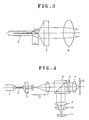
- Fig. 3 is a diagram showing the construction of an embodiment of the invention.
- Fig. 4 is a diagram showing the construction of an optical system of an optical pickup using the apparatus of Fig. 3 as a light source;
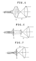
- Figs. 5 to 7 are diagrams showing the construction of other embodiments of the invention.
- a fiber type light wave-length converting apparatus comprises the primary light source 1, fiber type SHG 2, axicon lens 3, and condenser lens 4 in a manner similar to the conventional apparatus shown in Fig. 1.
- the axicon lens 3 is arranged at a position which satisfies the condition of
- L D/2tan ⁇ for the SHG 2 when it is assumed that a distance from the emitting edge surface of the SHG 2 to the front edge of the axicon lens 3 and an outer diameter of the SHG 2 are expressed by L and D respectively, and a Cerenkov angle (SH wave emitting angle) is expressed by ⁇ .
- the SH wave can be utilized efficiently. Therefore, if the fiber type light wave-length converting apparatus of the invention is used as a light source of an optical pickup, as shown in Fig. 4, the optical pickup can be constructed in a manner similar to the conventional optical system.
- the SH wave emitted from the axicon lens 3 is expanded by a beam expander optical system 12 and, thereafter, it enters the beam splitter 5.
- the axicon lens for converting the SH wave emitted from the SHG 2 into the parallel light is not limited to the construction of Fig. 3 but can be also constructed as shown in Fig. 5, 6, or 7. That is, there is a construction using a condenser lens compound type axicon lens 13 (Fig. 5) in which an axicon lens and a condenser lens on the incident side of a beam expander are constructed to an integrated form. There is a construction using a Fresnel type axicon lens 14 (Fig. 6). There is also a construction using a compound lens 15 (Fig.
- an axicon lens and a condenser lens on the incident side of a beam expander are constructed into an integrated form and one surface is formed as a Fresnel type axicon lens and the other surface is formed as a Fresnel type condenser lens.
- an axicon lens having a structure which can convert the SH wave emitted from the SHG 2 into the parallel light or a structure which can convert the SH wave into the parallel light and can focus the parallel light after the conversion.
- the axicon lens is arranged at a position which satisfies the condition of
Abstract
Description
- The present invention relates to a light wave-length converting apparatus of fiber type.
- There has been known an optical pickup in which a wave-length of a laser light beam which is generated from a laser light source is converted into a half wave-length by using a light wave-length converting apparatus, thereby enabling information to be written onto and to be read out from an optical disk at a higher density (reference is directed to Japanese Patent Application Provisional Publication No. 61-50122).
- A fiber type SHG (Second Harmonics Generator) using a secondary nonlinear optical effect has been known as a light wave-length converting apparatus. The fiber type SHG uses the phase matching of Cerenkov irradiation system. According to such a system, the second harmonic (hereinafter, abbreviated to an SH wave) is generated, to which phase matching is attained almost automatically.
- In the fiber type SHG using the Cerenkov phase matching, the emerging SH wave has a ring-like intensity distribution and its equiphase surface is conical. To focus such an SH wave to a diffraction limit, as shown in Fig. 1, an optical system is generally used which comprises a combination of: an
axicon lens 3 for converting an SH wave which was emitted from the primary light source 1 and wave-length converted by afiber type SHG 2 into a parallel light; and acondenser lens 4 for focusing the parallel light derived from theaxicon lens 3. On the other hand, in the case of using such an optical system as the light source of the optical pickup mentioned above, an optical system as shown in Fig. 2 is conceivable. - In Fig. 2, the parallel light from the
axicon lens 3 passes through abeam splitter 5 and is transmitted through a quarter wave-length (λ/4) plate 6. Thereafter, the light is focused onto an information recording surface of anoptical disk 8 by an objective lens 7 (corresponding to thecondenser lens 4 in Fig. 1). The reflected light from the information recording surface passes through theobjective lens 7 and the quarter wave-length plate 6. After that, the light is reflected by thebeam splitter 5. The reflected light then passes through acondenser lens 9 and acylindrical lens 10 and enters into the photo sensitive surface of aphotodetector 11. - As mentioned above, in the case of the optical pickup using the fiber type SHG including the combination of the
axicon lens 3 and theobjective lens 7 as a light source, since the light beam has a ring-like intensity distribution, the diameter of the light beam must be adjusted so as to sufficiently satisfy conditions determined a numerical aperture (NA) of theobjective lens 7. Further, if theobjective lens 7 is vibrated in the direction perpendicular to the optical axis by a tracking servo operation, the ring-like light beam would be interrupted by theobjective lens 7, so that a drawback will result such that the intensity distribution becomes uneven and a focused light spot is disturbed. - On the other hand, as a focused pattern which is obtained by focusing the light having the ring-like intensity distribution, a side lobe light amount increases as compared with the pattern of a light having a circular intensity distribution. Therefore, what is called a crosstalk, that is the leakage of information of adjacent pits on the information recording surface, increases and a central lobe light amount decreases, so that an actual light amount which can be used to read pit information decreases. Such a situation causes a large problem in the case where an efficiency of the SHG itself is relatively low.
- The above drawbacks are originated from the fact that the light of the light source has a ring-like intensity distribution.
- It is, therefore, an object of the invention to provide a fiber type light wave-length converting apparatus which can obtain an SH wave of a parallel light having a circular intensity distribution.
- A fiber type light wave-length converting apparatus according to the invention comprises: a fiber type SHG for converting the wave-length of an incident light; an axicon lens for converting the light emitted from the SHG into the parallel light; and a condenser lens for focusing the parallel light from the axicon lens, wherein the axicon lens is arranged at a position which satisfies the condition of
- L = D/2tan α
for the SHG when it is assumed that a distance from the emitting end surface of the SHG to the front end of the axicon lens is expressed by L and an outer diameter of the SHG is set to D and a Cerenkov angle is expressed by α. - In the fiber type light wave-length converting apparatus according to the invention, an SH wave of the parallel light having a circular intensity distribution is obtained by the positional relation which satisfies the above condition of the axicon lens for the SHG.
- Fig. 1 is a diagram showing an example of a conventional light wave-length converting apparatus;
- Fig. 2 is a diagram showing the construction of an optical system of an optical pickup using the apparatus of Fig. 1 as a light source;
- Fig. 3 is a diagram showing the construction of an embodiment of the invention;
- Fig. 4 is a diagram showing the construction of an optical system of an optical pickup using the apparatus of Fig. 3 as a light source; and
- Figs. 5 to 7 are diagrams showing the construction of other embodiments of the invention.
- An embodiment of the invention will be described in detail hereinafter with reference to Fig. 3.
- A fiber type light wave-length converting apparatus according to the invention comprises the primary light source 1,
fiber type SHG 2,axicon lens 3, andcondenser lens 4 in a manner similar to the conventional apparatus shown in Fig. 1. However, in the fiber type light wave-length converting apparatus according to the invention, as will be obviously understood from Fig. 3 showing an enlarged diagram of the main section of the apparatus, theaxicon lens 3 is arranged at a position which satisfies the condition of - L = D/2tan α
for theSHG 2 when it is assumed that a distance from the emitting edge surface of theSHG 2 to the front edge of theaxicon lens 3 and an outer diameter of theSHG 2 are expressed by L and D respectively, and a Cerenkov angle (SH wave emitting angle) is expressed by α. - According to the above construction, since an SH wave of a parallel light having a circular intensity distribution is obtained, the SH wave can be utilized efficiently. Therefore, if the fiber type light wave-length converting apparatus of the invention is used as a light source of an optical pickup, as shown in Fig. 4, the optical pickup can be constructed in a manner similar to the conventional optical system. In Fig. 4, the SH wave emitted from the
axicon lens 3 is expanded by a beam expanderoptical system 12 and, thereafter, it enters thebeam splitter 5. - The axicon lens for converting the SH wave emitted from the
SHG 2 into the parallel light is not limited to the construction of Fig. 3 but can be also constructed as shown in Fig. 5, 6, or 7. That is, there is a construction using a condenser lens compound type axicon lens 13 (Fig. 5) in which an axicon lens and a condenser lens on the incident side of a beam expander are constructed to an integrated form. There is a construction using a Fresnel type axicon lens 14 (Fig. 6). There is also a construction using a compound lens 15 (Fig. 7) in which an axicon lens and a condenser lens on the incident side of a beam expander are constructed into an integrated form and one surface is formed as a Fresnel type axicon lens and the other surface is formed as a Fresnel type condenser lens. In brief, it is sufficient to use an axicon lens having a structure which can convert the SH wave emitted from theSHG 2 into the parallel light or a structure which can convert the SH wave into the parallel light and can focus the parallel light after the conversion. - As described above, in the fiber type light wave-length converting apparatus according to the invention, since the axicon lens is arranged at a position which satisfies the condition of
- L = D/2tan α
for the SHG, the SH wave of the parallel light having a circular intensity distribution can be obtained. Therefore, such a fiber type light wave-length converting apparatus can be used as a light source of the optical pickup.
Claims (1)
- A light wave-length converting apparatus comprising:
a fiber type light wave-length converting element for converting a wave-length of an incident light;
an axicon lens for converting a light emitted from the light wave-length converting element into a parallel light; and
a condenser lens for focusing the parallel light from the axicon lens, wherein the axicon lens is arranged at a position which satisfies a condition of
L = D/2tan α
for the light wave-length converting element where L represents a distance from an emitting end surface of the light wave-length converting element to a front edge of the axicon lens, D represents an outer diameter of the light wave-length converting element, and α represents Cerenkov angle.
Applications Claiming Priority (2)
| Application Number | Priority Date | Filing Date | Title |
|---|---|---|---|
| JP306977/89 | 1989-11-27 | ||
| JP1306977A JPH03166531A (en) | 1989-11-27 | 1989-11-27 | Fiber type optical wavelength converting device |
Publications (2)
| Publication Number | Publication Date |
|---|---|
| EP0430183A2 true EP0430183A2 (en) | 1991-06-05 |
| EP0430183A3 EP0430183A3 (en) | 1992-03-18 |
Family
ID=17963542
Family Applications (1)
| Application Number | Title | Priority Date | Filing Date |
|---|---|---|---|
| EP19900122674 Withdrawn EP0430183A3 (en) | 1989-11-27 | 1990-11-27 | Fiber type light wave-length converting apparatus |
Country Status (3)
| Country | Link |
|---|---|
| US (1) | US5052772A (en) |
| EP (1) | EP0430183A3 (en) |
| JP (1) | JPH03166531A (en) |
Cited By (3)
| Publication number | Priority date | Publication date | Assignee | Title |
|---|---|---|---|---|
| EP0490291A1 (en) * | 1990-12-14 | 1992-06-17 | Sumitomo Electric Industries, Ltd. | Light source device |
| EP0527653A2 (en) * | 1991-08-14 | 1993-02-17 | Pioneer Electronic Corporation | Fiber type wavelength converter |
| EP0627643A2 (en) * | 1993-06-03 | 1994-12-07 | Hamamatsu Photonics K.K. | Laser scanning optical system using axicon |
Families Citing this family (5)
| Publication number | Priority date | Publication date | Assignee | Title |
|---|---|---|---|---|
| US6281993B1 (en) * | 1998-03-30 | 2001-08-28 | International Business Machines Corporation | Phase shifting element for optical information processing storing systems |
| US6496621B1 (en) * | 1998-09-22 | 2002-12-17 | Digital Optics Corp. | Fiber coupler system and associated methods for reducing back reflections |
| US8529139B2 (en) | 1998-09-22 | 2013-09-10 | Digitaloptics Corporation East | Optical element and system using the same |
| US6961489B2 (en) | 2003-06-30 | 2005-11-01 | Finisar Corporation | High speed optical system |
| JP6063670B2 (en) * | 2011-09-16 | 2017-01-18 | 株式会社アマダホールディングス | Laser cutting method and apparatus |
Citations (2)
| Publication number | Priority date | Publication date | Assignee | Title |
|---|---|---|---|---|
| JPS6150122A (en) * | 1984-08-18 | 1986-03-12 | Matsushita Electric Ind Co Ltd | Optical pickup |
| EP0342523A2 (en) * | 1988-05-14 | 1989-11-23 | Sumitomo Electric Industries, Ltd. | Generation of parallel second harmonic light rays using an optical fiber |
Family Cites Families (3)
| Publication number | Priority date | Publication date | Assignee | Title |
|---|---|---|---|---|
| JPH01293326A (en) * | 1988-05-20 | 1989-11-27 | Pioneer Electron Corp | Optical fiber type light wavelength converter |
| JP2686536B2 (en) * | 1988-05-20 | 1997-12-08 | パイオニア株式会社 | Fiber type optical wavelength converter |
| US4919511A (en) * | 1989-02-03 | 1990-04-24 | Pioneer Electronic Corporation | Fibre-type light conversion device |
-
1989
- 1989-11-27 JP JP1306977A patent/JPH03166531A/en active Pending
-
1990
- 1990-11-26 US US07/617,817 patent/US5052772A/en not_active Expired - Fee Related
- 1990-11-27 EP EP19900122674 patent/EP0430183A3/en not_active Withdrawn
Patent Citations (2)
| Publication number | Priority date | Publication date | Assignee | Title |
|---|---|---|---|---|
| JPS6150122A (en) * | 1984-08-18 | 1986-03-12 | Matsushita Electric Ind Co Ltd | Optical pickup |
| EP0342523A2 (en) * | 1988-05-14 | 1989-11-23 | Sumitomo Electric Industries, Ltd. | Generation of parallel second harmonic light rays using an optical fiber |
Non-Patent Citations (2)
| Title |
|---|
| PATENT ABSTRACTS OF JAPAN vol. 10, no. 210 (P-479)(2266) 23 July 1986 & JP-A-61 050 122 ( MATSUSHITA ) 12 March 1986 * |
| PROCEEDINGS OF THE SPIE: NONLINEAR OPTICAL PROPERTIES OF MATERIALS vol. 1148, 10 August 1989, SAN DIEGO, CALIFORNIA, US pages 207 - 212; UEMIYA ET AL: 'Crystal cored fiber using organic material and focussing properties of generalized second-harmonic wave' * |
Cited By (8)
| Publication number | Priority date | Publication date | Assignee | Title |
|---|---|---|---|---|
| EP0490291A1 (en) * | 1990-12-14 | 1992-06-17 | Sumitomo Electric Industries, Ltd. | Light source device |
| US5195159A (en) * | 1990-12-14 | 1993-03-16 | Sumitomo Electric Industries, Ltd. | Optical wavelength converter device |
| EP0527653A2 (en) * | 1991-08-14 | 1993-02-17 | Pioneer Electronic Corporation | Fiber type wavelength converter |
| EP0527653A3 (en) * | 1991-08-14 | 1993-10-20 | Pioneer Electronic Corp | Fiber type wavelength converter |
| EP0627643A2 (en) * | 1993-06-03 | 1994-12-07 | Hamamatsu Photonics K.K. | Laser scanning optical system using axicon |
| EP0627643A3 (en) * | 1993-06-03 | 1995-04-12 | Hamamatsu Photonics Kk | Laser scanning optical system using axicon. |
| US5583342A (en) * | 1993-06-03 | 1996-12-10 | Hamamatsu Photonics K.K. | Laser scanning optical system and laser scanning optical apparatus |
| US5796112A (en) * | 1993-06-03 | 1998-08-18 | Hamamatsu Photonics K.K. | Laser scanning optical system and laser scanning optical apparatus |
Also Published As
| Publication number | Publication date |
|---|---|
| JPH03166531A (en) | 1991-07-18 |
| EP0430183A3 (en) | 1992-03-18 |
| US5052772A (en) | 1991-10-01 |
Similar Documents
| Publication | Publication Date | Title |
|---|---|---|
| JP2788777B2 (en) | Optical pickup | |
| US5974020A (en) | Two-wavelength laser pick-up head for a DVD | |
| EP0444766A2 (en) | Optical pickup, optical information recording carrier and recording and reproducing apparatus thereof | |
| US4635244A (en) | Optical beam shaping system | |
| US5052772A (en) | Fiber type light wave-length converting apparatus | |
| US4235507A (en) | Optical system to condense light from a semiconductor laser into a circular spot | |
| JP2877044B2 (en) | Optical head device | |
| JPH0523411B2 (en) | ||
| US5737299A (en) | Optical pickup apparatus having wave plates | |
| JPH0291829A (en) | Optical head device | |
| JP2817452B2 (en) | Optical pickup device | |
| JP2655065B2 (en) | Super-resolution optical head device | |
| JP2636245B2 (en) | Optical head for magneto-optical storage | |
| JPH03166530A (en) | Fiber type light wavelength converting device | |
| JPS6356614B2 (en) | ||
| JPS6256581B2 (en) | ||
| JPH0954971A (en) | Optical pickup and reproducing device | |
| KR100339345B1 (en) | Optical pickup device | |
| KR100233115B1 (en) | Optical pickup device | |
| JP2538192B2 (en) | Optical disk drive | |
| KR100195082B1 (en) | Optical head | |
| JPS6182344A (en) | Optical pickup | |
| KR100200807B1 (en) | High density optical recording method and optical pickup using the method | |
| JPH0215434A (en) | Optical pickup | |
| KR100211820B1 (en) | An optical pick up device |
Legal Events
| Date | Code | Title | Description |
|---|---|---|---|
| PUAI | Public reference made under article 153(3) epc to a published international application that has entered the european phase |
Free format text: ORIGINAL CODE: 0009012 |
|
| AK | Designated contracting states |
Kind code of ref document: A2 Designated state(s): DE FR GB |
|
| RIN1 | Information on inventor provided before grant (corrected) |
Inventor name: OKAMOTO, KIYOFUMI Inventor name: OKAMOTO, SOTA |
|
| RIN1 | Information on inventor provided before grant (corrected) |
Inventor name: OKAMOTO, SOTA Inventor name: CHIKUMA, KIYOFUMI |
|
| PUAL | Search report despatched |
Free format text: ORIGINAL CODE: 0009013 |
|
| AK | Designated contracting states |
Kind code of ref document: A3 Designated state(s): DE FR GB |
|
| 17P | Request for examination filed |
Effective date: 19920527 |
|
| 17Q | First examination report despatched |
Effective date: 19931015 |
|
| STAA | Information on the status of an ep patent application or granted ep patent |
Free format text: STATUS: THE APPLICATION IS DEEMED TO BE WITHDRAWN |
|
| 18D | Application deemed to be withdrawn |
Effective date: 19941011 |