EP0429781B1 - Resume control system and method for executing resume processing while checking operation mode of CPU - Google Patents
Resume control system and method for executing resume processing while checking operation mode of CPU Download PDFInfo
- Publication number
- EP0429781B1 EP0429781B1 EP90117216A EP90117216A EP0429781B1 EP 0429781 B1 EP0429781 B1 EP 0429781B1 EP 90117216 A EP90117216 A EP 90117216A EP 90117216 A EP90117216 A EP 90117216A EP 0429781 B1 EP0429781 B1 EP 0429781B1
- Authority
- EP
- European Patent Office
- Prior art keywords
- cpu
- resume
- mode
- power source
- modes
- Prior art date
- Legal status (The legal status is an assumption and is not a legal conclusion. Google has not performed a legal analysis and makes no representation as to the accuracy of the status listed.)
- Expired - Lifetime
Links
Images


Classifications
-
- G—PHYSICS
- G06—COMPUTING; CALCULATING OR COUNTING
- G06F—ELECTRIC DIGITAL DATA PROCESSING
- G06F12/00—Accessing, addressing or allocating within memory systems or architectures
- G06F12/02—Addressing or allocation; Relocation
- G06F12/08—Addressing or allocation; Relocation in hierarchically structured memory systems, e.g. virtual memory systems
-
- G—PHYSICS
- G06—COMPUTING; CALCULATING OR COUNTING
- G06F—ELECTRIC DIGITAL DATA PROCESSING
- G06F9/00—Arrangements for program control, e.g. control units
- G06F9/06—Arrangements for program control, e.g. control units using stored programs, i.e. using an internal store of processing equipment to receive or retain programs
- G06F9/46—Multiprogramming arrangements
- G06F9/461—Saving or restoring of program or task context
-
- G—PHYSICS
- G06—COMPUTING; CALCULATING OR COUNTING
- G06F—ELECTRIC DIGITAL DATA PROCESSING
- G06F9/00—Arrangements for program control, e.g. control units
- G06F9/06—Arrangements for program control, e.g. control units using stored programs, i.e. using an internal store of processing equipment to receive or retain programs
- G06F9/44—Arrangements for executing specific programs
- G06F9/4401—Bootstrapping
- G06F9/4418—Suspend and resume; Hibernate and awake
Definitions
- This invention relates to a resume control system suitable for a personal computer having a resume function and also to a method used in the system.
- microprocessors and memory LSIs of high performance to be manufactured at very low cost.
- some of these microprocessors can simultaneously perform 8-bit processing, 16-bit processing, and 32-bit processing, and hence can process data at high speed.
- the following products, made by Intel Co., Ltd in the U.S.A., and generally used in personal computers, are listed as such microprocessors: iAPX86 (8086), iAPX88 (8088), iAPX186 (80186), iAPX286 (80286), and iAPX386 (80386).
- the iAPX286, can operate in two modes, i.e., real address mode and protective virtual address mode.
- real address mode a memory having a capacity of less than 1MB can be accessed, and the programs made for iAPX86 or iAPX186 also can be executed without being modified.
- protective virtual mode a memory having a capacity of 1MB or more can be accessed, and all functions of the iAPX286 are enabled, which include data protection, system integration, simultaneous processing of tasks, and management of memories such as a virtual memory.
- the protective virtual mode and real address mode are determined by setting and resetting a protection enabling bit provided in the iAPX286, respectively.
- the memories are addressed by the use of segment registers and offset registers in the real address mode, and addressed by the use of global descriptor tables (GDT), segment selectors, and offset registers, in the protective virtual address mode.
- GDT global descriptor tables
- the conventional resume processing programs can be executed in the real address mode only.
- the memories are addressed in different ways between the real address mode and protective virtual address mode. Accordingly, these conventional programs cannot be executed in the protective virtual address mode, unless they are modified.
- Document JP-A-1279312 published on 09/11/89 which corresponds to US-A-5435005 published on 18/07/95 discloses a method and a system for resuming data processing.
- the resuming mode is set after the computer system is bootloaded.
- the power source When the power switch is turned off, the power source generates a power switch-off signal.
- the resume mode the system data is stored in a file upon detection of the power switch-off signal. After a predetermined period of time has elapsed from the switch-off, or if a signal is generated for indicating that the storage of the system data has been completed, the power is cut off.
- An object of the present invention is to provide a resume control method and a system which can be operated with a simple control both in real address mode and in protective virtual address mode, by using a single resume processing program.
- CPU central processing unit
- a computer apparatus comprises a central processing unit (CPU) operable in first and second modes, and capable of executing a resume processing program set to be executed in one of the first and second modes; power source means for supplying power to said CPU; detecting means for detecting an abnormality in the power source means; storing means for storing the mode in which the CPU is operating, upon detection of the abnormality; setting means for setting said CPU to operate in one of the first and second modes in which the resume processing program can be executed; saving means for saving system data indicative of conditions of a program executed by said CPU when the abnormality of said power source means is detected; restoring means for restoring the saved system data, in response to a supplement of power from said power source means; and means for resuming the processing which has been executed by said CPU from the conditions when the system data was saved, based on the restored system data.
- CPU central processing unit
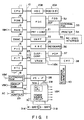
- Fig. 1 is a system block diagram of a personal computer system to which a resume control system and a method of the present invention are applied.
- a system bus 10 is connected to components 11 to 25.
- a CPU 11 controls the entire system.
- the CPU 11 has functions as shown in the flowcharts of Figs. 3 to 5, and serves as a host CPU viewed from a power control CPU 306 in a power source circuit 30 to be described later.
- a ROM 12 stores fixed programs, data and the like.
- a RAM 13 stores programs and data, to be processed, and also stores a resume mode flag, to be described later, and the like.
- a DMA controller 14 controls a direct memory access.
- a PIC (Programmable Interrupt Controller) 15 can be set by a program, and outputs an interrupt signal.
- a PIT (Programmable Interval Timer) 16 can be set by a program, and downcounts a set time period.
- a RTC (Real Time Clock) 17 has a dedicated power battery (not shown), and measurs the current time.
- An extension RAM 18, having a relatively large memory capacity, is removably inserted in a dedicated card slot of a main body, and is supplied with a backup power (VBK).
- a backup RAM 19 stores data for realizing a resume function, system data and a system data flag, to be described later. The RAM 19 is supplied with a backup power (VBK).
- a hard disk pack 20 is removably inserted in a dedicated housing section of a main body, and comprises a hard disk drive (HDD) 20A of, for example, 3.5 inches, and a hard disk controller (HDC) 20B for controlling the accessing by the drive 20A.
- HDD hard disk drive
- HDC hard disk controller
- Reference 20F designates a floppy disk controller (FDC); 21, a printer controller (PRT-CNT); 22, an input/output interface (UART; Universal Asynchronous Receiver); 23, a keyboard controller (KBC); and 24, a display controller (DISP-CONT).
- a video RAM (VRAM) 25 is supplied with a backup power (VBK), and stores display image data.
- a power source control interface (PS-IF) 28 connects the power source circuit 30 to the CPU 11 through the system bus 10. Upon receiving, from the power control CPU 306 in the power source circuit 30, power source abnormality data such as the cutoff of the power, and a low battery, the PS-IF 28 outputs an NMI (Non-Maskable Interrupt) signal, corresponding to the contents of the abnormality information, to the host CPU 11.
- NMI Non-Maskable Interrupt
- a power source adapter (AC adapter) 29 rectifies and smoothes commercially available alternating current (AC) to obtain direct current power of a predetermined potential.
- the AC adapter 29 is plugged in the personal computer main body.
- the power source circuit 30 supplies power to the respective components of the computer apparatus.
- a battery 31A serves to operate as a main battery (M-BATT), comprises a rechargeable battery, and is removably connected to the power source circuit 30.
- a battery 31B serves, to operate as a sub-battery, comprises a rechargeable battery, and is incorporated in the main body.
- a floppy disk drive (FDD) 32 is connected to the floppy disk controller 20F.
- An external floppy disk drive 33 is connected to the external floppy disk drive 33 as the necessity requires.
- a printer 34 is connected to the printer controller 21 as the necessity requires.
- An interface unit 35 is connected to the input/output interface 22 as the necessity requires, and comprises an RS-232C interface unit, etc.
- a keyboard 36 is connected to the keyboard controller 23.
- a PDP 37 is connected to the display controller 24.
- a CRT 38 is connected to the display controller 24 as the necessity requires.
- An extension unit is connected to an extension connector 40 as the necessity requires.
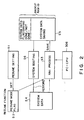
- Fig. 2 is a conceptual view for explaining an operation of a resume control system.
- the resume function is set to be enabled or disabled by a predetermined key operation, the input of a command, and the like (step S1).
- a resume mode flag indicative of the set mode in the step S1 is stored in the RAM 13.
- the power control (PC) CPU (PC-CPU) 306 provided in the power source circuit 30 monitors at all times the on/off state of the power sources provided in the computer system, irrespective of the on/off state of the main power source thereof. Upon detecting the abnormality of the power source, such as the cutoff of the power and the abnormal power source voltage, the PC-CPU 306 supplies the power control interface 28 with signals indicative of the occurrence of abnormality and the kind of the abnormality. Further, when a power switch 301 is turned off, the PC-CPU 306 supplies a signal indicative of it to the power control interface unit 28.
- PC power control
- the power control interface 28 Upon receiving the signal from the PC-CPU 306, the power control interface 28 outputs the NMI signal to the host CPU 11 in accordance with the contents thereof.
- the host CPU 11 Upon receiving the NMI signal, the host CPU 11 executes the NMI processing. More specifically, upon receiving the NMI signal indicative of the abnormality of the power sources, the CPU 11 starts the resume function, and stores in the backup RAM 19 the system data, data required for the data processing being executed including the contents of CPU registers, various LSI data, the value of a program counter, and the like. The CPU 11 also saves in the RAM 19 a system data flag indicating that the system data has been stored.
- the CPU 11 upon receiving the NMI signal indicative of the OFF state of the power switch 301 (that is, indicating that the system operation is normally completed), the CPU 11 refers to the resume mode flag. If the resume mode flag is ON (enable), the CPU 11 saves the system data in the backup RAM 19, and sets the system data flag indicating that the data has been saved. Then, the CPU 11 supplies a signal to the PC-CPU 306 to perform the power-off processing.
- the CPU 11 executes the power-off processing without carrying out the resume processing.
- the CPU 11 executes system boot processing, in which processing the CPU 11 refers to the system data stored in the backup RAM 19.
- Fig. 3 shows a flowchart of the NMI processing.
- a step A1 the CPU 11 determines the operation mode thereof. More specifically, the CPU 11 determines whether or not the aforementioned protection enabling bit is set. If the bit is set, the CPU operation mode is determined to be the protective virtual address mode, whereas if the bit is not set, it is determined to be the real address mode. Then, in a step A2, the CPU 11 is set to operate in a predetermined mode. In the embodiment, the resume control program is set to be executed in the real address mode. Thus, the CPU 11 is set in the step A2 to operate in the real address mode to thereby execute the resume control program.
- the CPU 11 determines in a step A3 whether or not the resume mode flag is set. If the flag is set, the CPU 11 saves the system data in the backup RAM 19 in step A4.
- the system data includes the contents of the CPU registers, the various LSI data, the value of the program counter, and the CPU operation mode determined in the step A1.
- the CPU 11 outputs a power-off command to the power source circuit 30.
- Fig. 4 shows a flowchart of the power-on processing.
- step B1 the CPU 11 refers to the system data flag, thereby determining whether or not the resume processing has been executed. If it is determined that the resume processing has been done, the CPU 11 restores the system data stored in the backup RAM 19 in step B2.
- step B3 the CPU 11 is set to operate in the mode determined in the step A1.
- step B4 the CPU 11 returns to the program interrupted by the NMI processing, and executes a command subsequent to the interrupted command.
- Fig. 5 shows a flowchart of setting the resume flag to be determined in step A3 of Fig. 3. This setting is carried out in the system set-up processing.
- the CPU 11 displays an inquiry menu on a PDP 37 in step C1, and in the next step C2 determines whether or not the resume mode is enabled by an input means of a keyboard or the like. If it is determined that the resume mode is enabled, the CPU 11 sets, in step C3, the resume mode flag. On the other hand, if it is determined in the step C2 that the resume mode is disabled, the CPU 11 resets, in step C4, the resume mode flag.
- the resume control program is set to be executed in the real address mode, and the operation mode of the CPU 11 is set to the real address mode in the step A2 to thereby execute the resume control program.
- the resume control program may be executed in the protective virtual address mode, and accordingly the CPU 11 may be set in the step A2 to operate in the protective virtual address mode.
Description
- This invention relates to a resume control system suitable for a personal computer having a resume function and also to a method used in the system.
- The development of semiconductor technology has enabled microprocessors and memory LSIs of high performance to be manufactured at very low cost. In particular, some of these microprocessors can simultaneously perform 8-bit processing, 16-bit processing, and 32-bit processing, and hence can process data at high speed. The following products, made by Intel Co., Ltd in the U.S.A., and generally used in personal computers, are listed as such microprocessors: iAPX86 (8086), iAPX88 (8088), iAPX186 (80186), iAPX286 (80286), and iAPX386 (80386).
- The iAPX286, for example, can operate in two modes, i.e., real address mode and protective virtual address mode. In the real address mode, a memory having a capacity of less than 1MB can be accessed, and the programs made for iAPX86 or iAPX186 also can be executed without being modified. In the protective virtual mode, a memory having a capacity of 1MB or more can be accessed, and all functions of the iAPX286 are enabled, which include data protection, system integration, simultaneous processing of tasks, and management of memories such as a virtual memory. The protective virtual mode and real address mode are determined by setting and resetting a protection enabling bit provided in the iAPX286, respectively.
- The memories are addressed by the use of segment registers and offset registers in the real address mode, and addressed by the use of global descriptor tables (GDT), segment selectors, and offset registers, in the protective virtual address mode.
- A personal computer, using the iAPX286 and having resume function, has been developed in recent years.
- Further, various application softwares, to be executed in the protective virtual mode, have been developed, though application softwares, made by microprocessors prior to the iAPX286, were prevailing before. This requires resume processing to be carried out in the protective virtual address mode.
- However, the conventional resume processing programs can be executed in the real address mode only. As is described above, the memories are addressed in different ways between the real address mode and protective virtual address mode. Accordingly, these conventional programs cannot be executed in the protective virtual address mode, unless they are modified.
- It makes the control complex to execute the programs for the real address mode in the protective virtual address mode. Alternatively, it costs a lot to prepare respective resume processing programs for the real address mode and protective virtual address mode.
- Document JP-A-1279312 published on 09/11/89 which corresponds to US-A-5435005 published on 18/07/95 discloses a method and a system for resuming data processing. In this method, the resuming mode is set after the computer system is bootloaded. When the power switch is turned off, the power source generates a power switch-off signal. In the resume mode, the system data is stored in a file upon detection of the power switch-off signal. After a predetermined period of time has elapsed from the switch-off, or if a signal is generated for indicating that the storage of the system data has been completed, the power is cut off. When the power switch is turned on again, the initialization of memories and the like, and the system data stored in the file are read out of it, and then restored in the memories. Thus, the data processing can be resumed in the state of the system having been assumed immediately before the power switch was turned off.
- An object of the present invention is to provide a resume control method and a system which can be operated with a simple control both in real address mode and in protective virtual address mode, by using a single resume processing program.
- According to a first aspect of the invention, a resume control method for a personal computer provided with a central processing unit (CPU) operable in first and second modes, and capable of executing a resume processing program set to be executed in one of the first and second modes comprises the steps of: a) determining and saving the mode in which the CPU is operating, in response to an abnormality of the power source; b) setting said CPU to operate in the one of the first and second modes in which the resume processing program can be executed; c) saving system data indicative of conditions in which the CPU has been operated upon the abnormality of the power source; d) restoring the system data saved in the step c), in response to a supplement of the power source; e) setting the CPU operation mode to the mode in which said CPU has been operated upon occurrence of the abnormality; and f) resuming the processing interrupted upon the occurrence of the abnormality of the power source.
- According to a second aspect of the invention, a computer apparatus comprises a central processing unit (CPU) operable in first and second modes, and capable of executing a resume processing program set to be executed in one of the first and second modes; power source means for supplying power to said CPU; detecting means for detecting an abnormality in the power source means; storing means for storing the mode in which the CPU is operating, upon detection of the abnormality; setting means for setting said CPU to operate in one of the first and second modes in which the resume processing program can be executed; saving means for saving system data indicative of conditions of a program executed by said CPU when the abnormality of said power source means is detected; restoring means for restoring the saved system data, in response to a supplement of power from said power source means; and means for resuming the processing which has been executed by said CPU from the conditions when the system data was saved, based on the restored system data.
- This invention can be more fully understood from the following detailed description when taken in conjunction with the accompanying drawings, in which:
- Fig. 1 is a system block diagram of a personal computer to which resume control system and method according to the present invention are applied;
- Fig. 2 is a conceptual view showing an outline of a resume processing according to the resume control system and method of the present invention;
- Fig. 3 is a flowchart of NMI processing executed in the resume-control system and method of the present invention;
- Fig. 4 is a flowchart of power-on processing executed in the resume control system and method of the present invention; and
- Fig. 5 is a flowchart of resume mode-setting processing executed in the resume-control system and method of the invention.
- Fig. 1 is a system block diagram of a personal computer system to which a resume control system and a method of the present invention are applied. As shown in Fig. 1, a
system bus 10 is connected to components 11 to 25. A CPU 11 controls the entire system. In this embodiment, the CPU 11 has functions as shown in the flowcharts of Figs. 3 to 5, and serves as a host CPU viewed from apower control CPU 306 in apower source circuit 30 to be described later. - A
ROM 12 stores fixed programs, data and the like. ARAM 13 stores programs and data, to be processed, and also stores a resume mode flag, to be described later, and the like. ADMA controller 14 controls a direct memory access. - A PIC (Programmable Interrupt Controller) 15 can be set by a program, and outputs an interrupt signal. A PIT (Programmable Interval Timer) 16 can be set by a program, and downcounts a set time period. A RTC (Real Time Clock) 17 has a dedicated power battery (not shown), and measurs the current time. An
extension RAM 18, having a relatively large memory capacity, is removably inserted in a dedicated card slot of a main body, and is supplied with a backup power (VBK). Abackup RAM 19 stores data for realizing a resume function, system data and a system data flag, to be described later. TheRAM 19 is supplied with a backup power (VBK). - A hard disk pack 20 is removably inserted in a dedicated housing section of a main body, and comprises a hard disk drive (HDD) 20A of, for example, 3.5 inches, and a hard disk controller (HDC) 20B for controlling the accessing by the
drive 20A.Reference 20F designates a floppy disk controller (FDC); 21, a printer controller (PRT-CNT); 22, an input/output interface (UART; Universal Asynchronous Receiver); 23, a keyboard controller (KBC); and 24, a display controller (DISP-CONT). A video RAM (VRAM) 25 is supplied with a backup power (VBK), and stores display image data. - A power source control interface (PS-IF) 28 connects the
power source circuit 30 to the CPU 11 through thesystem bus 10. Upon receiving, from thepower control CPU 306 in thepower source circuit 30, power source abnormality data such as the cutoff of the power, and a low battery, the PS-IF 28 outputs an NMI (Non-Maskable Interrupt) signal, corresponding to the contents of the abnormality information, to the host CPU 11. - A power source adapter (AC adapter) 29 rectifies and smoothes commercially available alternating current (AC) to obtain direct current power of a predetermined potential.
- The
AC adapter 29 is plugged in the personal computer main body. Thepower source circuit 30 supplies power to the respective components of the computer apparatus. - A
battery 31A serves to operate as a main battery (M-BATT), comprises a rechargeable battery, and is removably connected to thepower source circuit 30. Abattery 31B serves, to operate as a sub-battery, comprises a rechargeable battery, and is incorporated in the main body. A floppy disk drive (FDD) 32 is connected to thefloppy disk controller 20F. An external floppy disk drive 33 is connected to the external floppy disk drive 33 as the necessity requires. Aprinter 34 is connected to the printer controller 21 as the necessity requires. Aninterface unit 35 is connected to the input/output interface 22 as the necessity requires, and comprises an RS-232C interface unit, etc. Akeyboard 36 is connected to thekeyboard controller 23. APDP 37 is connected to thedisplay controller 24. A CRT 38 is connected to thedisplay controller 24 as the necessity requires. An extension unit is connected to anextension connector 40 as the necessity requires. - Fig. 2 is a conceptual view for explaining an operation of a resume control system.
- In the set-up mode, the resume function is set to be enabled or disabled by a predetermined key operation, the input of a command, and the like (step S1). As a result, a resume mode flag indicative of the set mode in the step S1, is stored in the
RAM 13. - The power control (PC) CPU (PC-CPU) 306 provided in the
power source circuit 30 monitors at all times the on/off state of the power sources provided in the computer system, irrespective of the on/off state of the main power source thereof. Upon detecting the abnormality of the power source, such as the cutoff of the power and the abnormal power source voltage, the PC-CPU 306 supplies thepower control interface 28 with signals indicative of the occurrence of abnormality and the kind of the abnormality. Further, when a power switch 301 is turned off, the PC-CPU 306 supplies a signal indicative of it to the powercontrol interface unit 28. - Upon receiving the signal from the PC-
CPU 306, thepower control interface 28 outputs the NMI signal to the host CPU 11 in accordance with the contents thereof. - Upon receiving the NMI signal, the host CPU 11 executes the NMI processing. More specifically, upon receiving the NMI signal indicative of the abnormality of the power sources, the CPU 11 starts the resume function, and stores in the
backup RAM 19 the system data, data required for the data processing being executed including the contents of CPU registers, various LSI data, the value of a program counter, and the like. The CPU 11 also saves in the RAM 19 a system data flag indicating that the system data has been stored. - Moreover, upon receiving the NMI signal indicative of the OFF state of the power switch 301 (that is, indicating that the system operation is normally completed), the CPU 11 refers to the resume mode flag. If the resume mode flag is ON (enable), the CPU 11 saves the system data in the
backup RAM 19, and sets the system data flag indicating that the data has been saved. Then, the CPU 11 supplies a signal to the PC-CPU 306 to perform the power-off processing. - On the other hand, if the resume mode flag is OFF, the CPU 11 executes the power-off processing without carrying out the resume processing.
- When the power switch 301 is again turned on, or if the power source voltage is recovered to the predetermined value, the CPU 11 executes system boot processing, in which processing the CPU 11 refers to the system data stored in the
backup RAM 19. - Then, the operation of this embodiment will be explained with reference to Figs. 3 to 5.
- Fig. 3 shows a flowchart of the NMI processing.
- In a step A1, the CPU 11 determines the operation mode thereof. More specifically, the CPU 11 determines whether or not the aforementioned protection enabling bit is set. If the bit is set, the CPU operation mode is determined to be the protective virtual address mode, whereas if the bit is not set, it is determined to be the real address mode. Then, in a step A2, the CPU 11 is set to operate in a predetermined mode. In the embodiment, the resume control program is set to be executed in the real address mode. Thus, the CPU 11 is set in the step A2 to operate in the real address mode to thereby execute the resume control program.
- Then, the CPU 11 determines in a step A3 whether or not the resume mode flag is set. If the flag is set, the CPU 11 saves the system data in the
backup RAM 19 in step A4. The system data includes the contents of the CPU registers, the various LSI data, the value of the program counter, and the CPU operation mode determined in the step A1. In step A5, the CPU 11 outputs a power-off command to thepower source circuit 30. - Fig. 4 shows a flowchart of the power-on processing.
- In step B1, the CPU 11 refers to the system data flag, thereby determining whether or not the resume processing has been executed. If it is determined that the resume processing has been done, the CPU 11 restores the system data stored in the
backup RAM 19 in step B2. - In step B3, the CPU 11 is set to operate in the mode determined in the step A1. In step B4, the CPU 11 returns to the program interrupted by the NMI processing, and executes a command subsequent to the interrupted command.
- Fig. 5 shows a flowchart of setting the resume flag to be determined in step A3 of Fig. 3. This setting is carried out in the system set-up processing.
- The CPU 11 displays an inquiry menu on a
PDP 37 in step C1, and in the next step C2 determines whether or not the resume mode is enabled by an input means of a keyboard or the like. If it is determined that the resume mode is enabled, the CPU 11 sets, in step C3, the resume mode flag. On the other hand, if it is determined in the step C2 that the resume mode is disabled, the CPU 11 resets, in step C4, the resume mode flag. - Note that in the above-described embodiment, the resume control program is set to be executed in the real address mode, and the operation mode of the CPU 11 is set to the real address mode in the step A2 to thereby execute the resume control program. However, the present invention is not limited to the above embodiment. The resume control program may be executed in the protective virtual address mode, and accordingly the CPU 11 may be set in the step A2 to operate in the protective virtual address mode.
Claims (10)
- A resume control method for a personal computer having a central processing unit (CPU) operable in first and second modes, and capable of executing a resume processing program set to be executed in one of the first and second modes, which comprises processings of saving system data in response to an interrupt signal regarding a power source, and restoring the system data in response to a restoration process of the personal computer, characterized by comprising the steps of:a) saving (A1) a state in which the CPU is operating, in response to the interrupt signal;b) setting (A2) the CPU to operate in the one of the first and second modes in which the resume processing program can be executed, and performing a save operation of the system data; andc) setting (B3) the CPU to operate in the same mode as the CPU was operating at the time of the occurrence of the interrupt, after the restoration processing has been completed.
- The method according to claim 1, characterized by further comprising:detecting the interrupt of the power source; andsupplying the CPU with the interrupt signal responsive to the interrupt of the power source.
- The method according to claim 1, characterized in that memories are addressed in different ways between the first and second modes.
- The method according to claim 1, characterized by further comprising:setting resume function either enabled or disenabled; andexecuting a resume processing program if the resume function is set enabled.
- The method according to claim 1, characterized in that the resume processing program is executable in the first mode, and not executable in the second mode, and said step b) sets the CPU to operate in the first mode.
- A resume control apparatus for a personal computer having a central processing unit (CPU) operable in first and second modes and a power source for supplying power to the CPU, the CPU capable of executing a resume processing program set to be executed in one of the first and second modes, which program comprises the processings of saving the system data upon occurrence of an interrupt signal regarding a power source, and restoring the system data upon a restoration process of the personal computer, characterized by comprising:means (11, A11) for saving the state in which the CPU is operating in response to the interrupt signal;means (11, A2) for setting the CPU to operate in the one of the first and second modes in which the resume processing program is executable, and performing a save processing of the system data; and means (11, B3) for setting the CPU to operate in the same mode as the CPU was operating at the time of the occurrence of the interrupt signal, after restoration processing has been completed.
- The apparatus according to claim 6, characterized by further comprising means for supplying the CPU with the interrupt signal responsive to the interrupt of the power source.
- The apparatus according to claim 6, characterized in that memories are addressed in different ways between the first and second modes.
- The apparatus according to claim 6, characterized by further comprising means for setting resume function either enabled or disenabled, and means for executing a resume processing program if the resume function is set enabled.
- The apparatus according to claim 6, characterized in that the resume processing program can be executed in the first mode, and cannot be executed in the second mode, and the setting means includes means for setting the CPU to operate in the first mode.
Applications Claiming Priority (2)
| Application Number | Priority Date | Filing Date | Title |
|---|---|---|---|
| JP309124/89 | 1989-11-30 | ||
| JP1309124A JP2644348B2 (en) | 1989-11-30 | 1989-11-30 | Computer system |
Publications (3)
| Publication Number | Publication Date |
|---|---|
| EP0429781A2 EP0429781A2 (en) | 1991-06-05 |
| EP0429781A3 EP0429781A3 (en) | 1992-05-20 |
| EP0429781B1 true EP0429781B1 (en) | 1996-07-10 |
Family
ID=17989181
Family Applications (1)
| Application Number | Title | Priority Date | Filing Date |
|---|---|---|---|
| EP90117216A Expired - Lifetime EP0429781B1 (en) | 1989-11-30 | 1990-09-06 | Resume control system and method for executing resume processing while checking operation mode of CPU |
Country Status (4)
| Country | Link |
|---|---|
| EP (1) | EP0429781B1 (en) |
| JP (1) | JP2644348B2 (en) |
| KR (1) | KR930002327B1 (en) |
| DE (1) | DE69027742T2 (en) |
Families Citing this family (5)
| Publication number | Priority date | Publication date | Assignee | Title |
|---|---|---|---|---|
| US5355490A (en) * | 1991-06-14 | 1994-10-11 | Toshiba America Information Systems, Inc. | System and method for saving the state for advanced microprocessor operating modes |
| EP0523652B1 (en) * | 1991-07-16 | 1999-02-03 | Canon Kabushiki Kaisha | Electronic apparatus with resume function |
| DE4309532C2 (en) * | 1992-03-25 | 1996-10-31 | Intel Corp | Method for backing up a system image of a computer system on a permanent storage device and a computer system |
| JP5284401B2 (en) | 2011-03-24 | 2013-09-11 | 株式会社東芝 | Operation switching device and program |
| CN111984338B (en) * | 2020-07-27 | 2021-11-09 | 未来穿戴技术有限公司 | Mode collection method, device, mobile terminal and computer readable storage medium |
Family Cites Families (3)
| Publication number | Priority date | Publication date | Assignee | Title |
|---|---|---|---|---|
| US4779187A (en) * | 1985-04-10 | 1988-10-18 | Microsoft Corporation | Method and operating system for executing programs in a multi-mode microprocessor |
| JPS62169218A (en) * | 1986-01-17 | 1987-07-25 | インタ−ナショナル ビジネス マシ−ンズ コ−ポレ−ション | Application suspension restarter for information processing system |
| US4763333A (en) * | 1986-08-08 | 1988-08-09 | Universal Vectors Corporation | Work-saving system for preventing loss in a computer due to power interruption |
-
1989
- 1989-11-30 JP JP1309124A patent/JP2644348B2/en not_active Expired - Lifetime
-
1990
- 1990-09-05 KR KR1019900013969A patent/KR930002327B1/en not_active IP Right Cessation
- 1990-09-06 DE DE69027742T patent/DE69027742T2/en not_active Expired - Lifetime
- 1990-09-06 EP EP90117216A patent/EP0429781B1/en not_active Expired - Lifetime
Also Published As
| Publication number | Publication date |
|---|---|
| EP0429781A2 (en) | 1991-06-05 |
| DE69027742D1 (en) | 1996-08-14 |
| EP0429781A3 (en) | 1992-05-20 |
| JP2644348B2 (en) | 1997-08-25 |
| KR910010317A (en) | 1991-06-29 |
| JPH03171217A (en) | 1991-07-24 |
| DE69027742T2 (en) | 1996-11-28 |
| KR930002327B1 (en) | 1993-03-29 |
Similar Documents
| Publication | Publication Date | Title |
|---|---|---|
| US5276890A (en) | Resume control system and method for executing resume processing while checking operation mode of CPU | |
| AU685455B2 (en) | Desktop computer system having multi-level power management | |
| US5021983A (en) | Suspend/resume apparatus and method for reducing power consumption in battery powered computers | |
| EP0635788B1 (en) | Method and apparatus for saving and restoring the state of a CPU | |
| EP0635778B1 (en) | Desktop computer having a single-switch suspend/resume function | |
| CA2120056C (en) | Desktop computer system having zero volt system suspend | |
| KR100188501B1 (en) | Multiple user computer system | |
| KR100232314B1 (en) | Multifunction power switch and feedback led for suspend systems | |
| EP0483865A2 (en) | Personal computer capable of changing boot priority | |
| US5291604A (en) | Transparent system interrupts with automated halt state restart | |
| US5469565A (en) | Personal computer for disabling resume mode upon replacement of HDD | |
| US7360045B2 (en) | System and method for backing up data from a quiesced storage device | |
| JPH05189075A (en) | Lithium processing method for os/2 operating system | |
| EP0404061A2 (en) | Computer having a resume function and operable on an internal power source | |
| JP3253881B2 (en) | Computer system and hibernation control method in the system | |
| EP0429781B1 (en) | Resume control system and method for executing resume processing while checking operation mode of CPU | |
| JPH11194847A (en) | Computer system and initialization controller | |
| US7093142B2 (en) | Method, apparatus and program for user-determined operational state of a portable computer prior to detachment | |
| JP2972651B2 (en) | Message display control method when inserting / removing PC card | |
| JP2997584B2 (en) | Power control device | |
| JPH10240367A (en) | Computer system and suspend control method for the same | |
| KR100207884B1 (en) | Method and apparatus for suspend/resume operation in a computer | |
| JPH06102955A (en) | Power controller for portable computer | |
| JPH03269635A (en) | Personal computer | |
| JPH05189099A (en) | Power controller for computer |
Legal Events
| Date | Code | Title | Description |
|---|---|---|---|
| PUAI | Public reference made under article 153(3) epc to a published international application that has entered the european phase |
Free format text: ORIGINAL CODE: 0009012 |
|
| 17P | Request for examination filed |
Effective date: 19901002 |
|
| AK | Designated contracting states |
Kind code of ref document: A2 Designated state(s): DE FR GB |
|
| PUAL | Search report despatched |
Free format text: ORIGINAL CODE: 0009013 |
|
| AK | Designated contracting states |
Kind code of ref document: A3 Designated state(s): DE FR GB |
|
| 17Q | First examination report despatched |
Effective date: 19950926 |
|
| GRAH | Despatch of communication of intention to grant a patent |
Free format text: ORIGINAL CODE: EPIDOS IGRA |
|
| GRAH | Despatch of communication of intention to grant a patent |
Free format text: ORIGINAL CODE: EPIDOS IGRA |
|
| GRAA | (expected) grant |
Free format text: ORIGINAL CODE: 0009210 |
|
| AK | Designated contracting states |
Kind code of ref document: B1 Designated state(s): DE FR GB |
|
| REF | Corresponds to: |
Ref document number: 69027742 Country of ref document: DE Date of ref document: 19960814 |
|
| ET | Fr: translation filed | ||
| PLBE | No opposition filed within time limit |
Free format text: ORIGINAL CODE: 0009261 |
|
| STAA | Information on the status of an ep patent application or granted ep patent |
Free format text: STATUS: NO OPPOSITION FILED WITHIN TIME LIMIT |
|
| 26N | No opposition filed | ||
| REG | Reference to a national code |
Ref country code: GB Ref legal event code: IF02 |
|
| PGFP | Annual fee paid to national office [announced via postgrant information from national office to epo] |
Ref country code: GB Payment date: 20090902 Year of fee payment: 20 |
|
| PGFP | Annual fee paid to national office [announced via postgrant information from national office to epo] |
Ref country code: DE Payment date: 20090903 Year of fee payment: 20 |
|
| PGFP | Annual fee paid to national office [announced via postgrant information from national office to epo] |
Ref country code: FR Payment date: 20091012 Year of fee payment: 20 |
|
| REG | Reference to a national code |
Ref country code: GB Ref legal event code: PE20 Expiry date: 20100905 |
|
| PG25 | Lapsed in a contracting state [announced via postgrant information from national office to epo] |
Ref country code: GB Free format text: LAPSE BECAUSE OF EXPIRATION OF PROTECTION Effective date: 20100905 |
|
| PG25 | Lapsed in a contracting state [announced via postgrant information from national office to epo] |
Ref country code: DE Free format text: LAPSE BECAUSE OF EXPIRATION OF PROTECTION Effective date: 20100906 |