EP0429766A2 - Methods and apparatus for marking and identifying hooks of electric motors - Google Patents
Methods and apparatus for marking and identifying hooks of electric motors Download PDFInfo
- Publication number
- EP0429766A2 EP0429766A2 EP90116086A EP90116086A EP0429766A2 EP 0429766 A2 EP0429766 A2 EP 0429766A2 EP 90116086 A EP90116086 A EP 90116086A EP 90116086 A EP90116086 A EP 90116086A EP 0429766 A2 EP0429766 A2 EP 0429766A2
- Authority
- EP
- European Patent Office
- Prior art keywords
- workpiece
- processing operation
- predetermined
- force
- unmarked
- Prior art date
- Legal status (The legal status is an assumption and is not a legal conclusion. Google has not performed a legal analysis and makes no representation as to the accuracy of the status listed.)
- Granted
Links
Images


Classifications
-
- H—ELECTRICITY
- H02—GENERATION; CONVERSION OR DISTRIBUTION OF ELECTRIC POWER
- H02K—DYNAMO-ELECTRIC MACHINES
- H02K15/00—Methods or apparatus specially adapted for manufacturing, assembling, maintaining or repairing of dynamo-electric machines
- H02K15/08—Forming windings by laying conductors into or around core parts
- H02K15/09—Forming windings by laying conductors into or around core parts by laying conductors into slotted rotors
-
- Y—GENERAL TAGGING OF NEW TECHNOLOGICAL DEVELOPMENTS; GENERAL TAGGING OF CROSS-SECTIONAL TECHNOLOGIES SPANNING OVER SEVERAL SECTIONS OF THE IPC; TECHNICAL SUBJECTS COVERED BY FORMER USPC CROSS-REFERENCE ART COLLECTIONS [XRACs] AND DIGESTS
- Y10—TECHNICAL SUBJECTS COVERED BY FORMER USPC
- Y10T—TECHNICAL SUBJECTS COVERED BY FORMER US CLASSIFICATION
- Y10T29/00—Metal working
- Y10T29/49—Method of mechanical manufacture
- Y10T29/49002—Electrical device making
- Y10T29/49004—Electrical device making including measuring or testing of device or component part
-
- Y—GENERAL TAGGING OF NEW TECHNOLOGICAL DEVELOPMENTS; GENERAL TAGGING OF CROSS-SECTIONAL TECHNOLOGIES SPANNING OVER SEVERAL SECTIONS OF THE IPC; TECHNICAL SUBJECTS COVERED BY FORMER USPC CROSS-REFERENCE ART COLLECTIONS [XRACs] AND DIGESTS
- Y10—TECHNICAL SUBJECTS COVERED BY FORMER USPC
- Y10T—TECHNICAL SUBJECTS COVERED BY FORMER US CLASSIFICATION
- Y10T29/00—Metal working
- Y10T29/49—Method of mechanical manufacture
- Y10T29/49002—Electrical device making
- Y10T29/49009—Dynamoelectric machine
- Y10T29/49011—Commutator or slip ring assembly
-
- Y—GENERAL TAGGING OF NEW TECHNOLOGICAL DEVELOPMENTS; GENERAL TAGGING OF CROSS-SECTIONAL TECHNOLOGIES SPANNING OVER SEVERAL SECTIONS OF THE IPC; TECHNICAL SUBJECTS COVERED BY FORMER USPC CROSS-REFERENCE ART COLLECTIONS [XRACs] AND DIGESTS
- Y10—TECHNICAL SUBJECTS COVERED BY FORMER USPC
- Y10T—TECHNICAL SUBJECTS COVERED BY FORMER US CLASSIFICATION
- Y10T29/00—Metal working
- Y10T29/53—Means to assemble or disassemble
- Y10T29/5313—Means to assemble electrical device
- Y10T29/53143—Motor or generator
- Y10T29/53157—Means to stake wire to commutator or armature
-
- Y—GENERAL TAGGING OF NEW TECHNOLOGICAL DEVELOPMENTS; GENERAL TAGGING OF CROSS-SECTIONAL TECHNOLOGIES SPANNING OVER SEVERAL SECTIONS OF THE IPC; TECHNICAL SUBJECTS COVERED BY FORMER USPC CROSS-REFERENCE ART COLLECTIONS [XRACs] AND DIGESTS
- Y10—TECHNICAL SUBJECTS COVERED BY FORMER USPC
- Y10T—TECHNICAL SUBJECTS COVERED BY FORMER US CLASSIFICATION
- Y10T29/00—Metal working
- Y10T29/53—Means to assemble or disassemble
- Y10T29/5313—Means to assemble electrical device
- Y10T29/53143—Motor or generator
- Y10T29/53161—Motor or generator including deforming means
Definitions
- the present invention relates to armature winding machines, and, more particularly, to machines for winding the armature wires of an electric motor to a hook member ("tang") of a commutator bar and deforming selected hook members for later identification during processing.
- the conditions required for fusing commutator hooks vary depending upon the number of armature lead wires that are passed around a given hook.
- the fusing conditions must be tailored to the hook's winding configuration if a satisfactory fusion joint is to be formed. For example, a hook with a single wire passed around it will require a different electrode displacement, electrode force, and electric current application than a hook with two wires passed around it.
- the hook wrapped with two wires may require additional electrode force to produce a cohesion joint of satisfactory quality.
- Winding machines typically attach two armature lead wires to selected hooks during the termination stages of armature winding. At the instant a hook is wrapped with two wires, the armature has a precise, known angular position. Thus, it would be possible to transfer a wound armature to a fusing machine while in a known angular position. The hooks wrapped with two wires could be recognized by their angular position and appropriately processed. However, such a solution requires costly changes to the transfer solutions between the winding and fusing machines.
- a winding machine which deforms preselected commutator hooks, yet does not deform other hooks.
- the machine deforms the hooks while the hooks are in a known angular position.
- Apparatus is provided, for processing the hooks after winding, which includes means for measuring either the hook deformation or the force exerted on a sensing member.
- a machine for processing the hook such as a fusing machine, which includes a force transducer for measuring electrode pressure, and an encoder for accurately determining the electrode displacement.
- the electrode force and displacement measurements will vary, depending upon whether or not the electrode is operating on a hook that was deformed by the winding machine.
- a microprocessor-based control system receives force and displacement data from the load cell and encoder, respectively, and acts on a motor to modify those quantities.
- the microprocessor recognizes hooks that were previously deformed by the winding machine, and causes the fusing machine to execute a predetermined operation. The operation performed on a deformed hook may be different than the operation performed on a non-deformed hook.
- the microprocessor stores a distinct, predetermined electrode displacement or force function for fusing each hook variation that the apparatus can process. Electrode position or force may be continuously measured and adjusted according to the appropriate function.
- the apparatus applies current to the electrode when the electrode has a predetermined displacement or force, and may vary the current application according to whether or not the hook under operation was deformed (marked) by the winding machine.
- FIG. 1 is a partial perspective view of an illustrative embodiment of an armature winding machine in accordance with the present invention
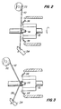
- FIGS. 2 and 3 are partial side elevational views of a commutator with a hook being wrapped with a lead wire by the winding machine of FIG. 1;
- FIG. 4 is a partial side elevational view of the commutator and the hook of FIG. 3, after the lead wire is cut at a point between the hook and a gripper;
- FIG. 4a is a partial bottom view of the hook of FIG. 4;
- FIG. 5 is a partial side elevational view of a commutator with hooks that are wrapped with a single wire
- FIG. 6 is a partial side elevational view of a commutator with a hook being wrapped with a finish lead;
- FIG. 7a is a partial side view of the center commutator hook of FIG. 6, showing the wrapping of the start and finish lead around the same hook;
- FIG. 7b is a partial side view of the center commutator hook of FIG. 6, showing the start and finish leads wrapped around a hook with an uninterrupted wire;
- FIG. 8 is a partial side elevational view of a commutator having two hooks wrapped with a single wire, and one hook wrapped with two wires;
- FIG. 9 is a side elevational view of an illustrative embodiment of apparatus of this invention for positioning an armature adjacent a deforming member
- FIG. 10 is a cross-sectional view of an illustrative embodiment of a fusing machine constructed in accordance with the principles of this invention.
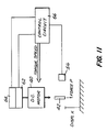
- FIG. 11 is a schematic diagram of the feedback loop control system of this invention, which can be used in the fusing machine of FIG. 10;
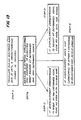
- FIG. 12 a flowchart of a feedback loop for recognizing a previously deformed commutator hook
- FIG. 13 is a flowchart of an alternative feedback loop for recognizing a previously deformed commutator hook.
- FIG. 14 is a flowchart illustrating a process for distinguishing between commutator hooks that have not been deformed during an earlier operation.
- FIGS. 1-8 illustrate the process for winding a lead wire 10 of an armature to a commutator bar 12.
- Wire 10 is wrapped around a hook 14 on commutator bar 12.
- a two-flyer winding machine 16 removes wire 10 from a coil and passes it around hook 14.
- An unwound armature 18 rests on winding machine 16 in winding receiving position.
- Wire 10 passes around a roller 20 and then around a flyer 22.
- Wire 10 stretches from flyer 22 to a gripper 24.
- Gripper 24 reciprocates during winding to draw wire 10 from a supply roll and over roller 20 and flyer 22.
- the gripper's reciprocating action attaches the wire lead to hook 14 (FIG. 2).
- Initial and final leads are attached to the appropriate hooks and then cut by the operation of flyer 22, gripper 24, a cutter, and other equipment.
- start lead 26 (FIG. 3) is attached to the armature around a first hook by rotation of flyer 22. Wire 10 is then cut (see FIGS. 4 and 4a) between hook 14 and gripper 24 (near the hook) to free gripper 24 and leave start lead 26 wrapped around the hook.
- Flyer 22 and other equipment then operate to wind wire coils in the appropriate armature slots, and to loop the wire around the respective hooks.
- a single wire is passed around each hook (see FIG. 5) when the coils are being wound. The continuity of the wire is not interrupted.
- flyer 22 When flyer 22 has completed winding all of the coils that must be wound, a stretch of wire extends from the flyer to the last wound coil. Flyer 22 and other equipment then operate to loop the finish lead 28 around the last hook (see FIG. 6). Gripper 24 grips the stretch of wire leading from the hook to the flyer, and the wire is severed at a point near the hook. A new armature may then be wound.
- FIG. 7a shows the start and finish leads of the two flyers wrapped behind the same hook.
- the start and finish leads may be on a hook which is also wrapped with an uninterrupted lead (FIG. 7b).
- the armature is rotated with the same equipment used to hold and rotate the armature during winding.
- the hooks wrapped with more than one wire are positioned under a deforming member 30.
- Deforming member 30 is displaced a predetermined distance along the deforming axis 31 to deform the hooks wrapped with two wires.
- Member 30 is driven by numerically-controlled axial actuators for high precision operations or when more than one deformed position is required. When less precision is required, conventional, less complex actuators can be used to drive deforming member 30.
- a plurality of deforming members may be used to increase operating speed.
- the deformed hooks 32 are bent towards the commutator bar 33.
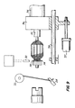
- Deforming member 30 typically may be part of the winding apparatus. Hook 32 may be deformed while still in its winding position with a known angular position. Alternatively, the deforming step may be performed by a machine (FIG. 9) that unloads the armature from winding machine 16 and places it on a transfer mechanism. The armature is removed from the winding machine and positioned beneath deforming member 30. An activator 34 controls a collet 35, which releasably holds the shaft of the armature in a known angular position. A shuttle 36 is moved by member 37 along guides 38 to withdraw the armature from winding machine 16, positioning the armature adjacent deforming member 30. After member 30 marks the appropriate hook, the armature may be transferred to other equipment for further processing.
- deformed hook 32 has a different position, relative to commutator bar 33, than the upper surface of non-deformed hooks l4.
- Apparatus that is sensitive to force exerted on a translating member, or which can detect the displacement of a translating member along an axis of translation, is used to distinguish deformed hooks 32 (wrapped with several wires) from non-deformed hooks 14 (wrapped with a single wire). In this manner, subsequent processing equipment, such as a fusing machine, can automatically identify hooks wrapped with more than one wire.
- Distinguishing between the commutator hooks wrapped with more than one wire and hooks wrapped with a single wire enables the fusing machine to perform a different fusing operation on each type of hook.
- Deforming hooks during the winding operation offers the additional advantage of exerting additional pressure on the wrapped wires. This aids in holding the wires under the hook during subsequent transfer and handling of the armature.
- Fusing machines capable of recognizing hooks deformed during the winding operation typically include one or more sensing elements.
- the sensing elements measure force exerted on a hook as a function of time or as a function of fusing electrode displacement. Alternatively, the sensing elements detect electrode displacement as a function of time or electrode force.
- Fusing apparatus suitable for this purpose is described in commonly owned, co-pending U.S. patent Application Serial No. 07/412,279, which is hereby incorporated by reference herein.
- the fusing operation may be tailored to the condition of the particular hook being fused. This permits a better fusion joint to be produced.
- the heat i.e., electric current
- force applied to the hooks, and the displacement performance of the electrode are tailored to obtain the ideal fusing condition, which results in the correct electrical resistance and sufficient mechanical resistance of the connection.
- a fusing electrode typically must generate more heat to fuse a hook wrapped with two wires in order to remove the greater quantity of wire insulation. The extra heat must be combined with the appropriate force and displacement performance of the electrode.
- FIG. 10 shows a fusing machine in which the rotational motion of a motor 40 is converted into translational motion of fusing electrode 42 along axis 31.
- a rotation of motor output drive shaft 44 will cause a ball screw 46 to rotate.
- the engagement of ball screw 46 with sleeve 48 causes hollow member 50, hollow member 52, and electrode 42 to translate along electrode axis 31.
- a roller 54 maintains the alignment of hollow members 50 and 52 along axis 31.
- a force transducer such as load cell 56
- a space 58 allows hollow member 52 to translate along hollow member 50, and allows load cell 56 to deform correspondingly.
- a mass electrode 60 contacts the commutator during fusing to provide a current sink for electricity flowing from electrode 42.
- the fusing machine can monitor and adjust the electrode displacement and force.
- the displacement is derived, using encoder 62, from the number of turns of motor drive shaft 44.
- Load cell 56 measures the force resistance against the electrode.
- Microprocessor circuit 66 acts in response to data received from either the encoder or the load cell.
- Microprocessor circuit 66 causes the motor to precisely lower (or raise) electrode 42.
- the microprocessor changes the field conditions of motor 40 to control the motor's torque.
- the apparatus can be used to implement the feedback loops shown in FIGS. 12 and 13, to distinguish deformed hooks from non-deformed hooks, and to perform a different processing operation on each type of hook.
- a feedback measurement loop provides a means for displacing a fusing electrode of a fusing machine a predetermined distance, corresponding to a position slightly below the upper surface of a non-deformed hook (step A).
- the feedback loop measures the force on the electrode (step B). If the electrode force is within a predetermined range, the hook is recognized as a hook wrapped with a single wire.
- the hook is then fused according to a predetermined electrical current application function and electrode force or displacement function (step C), e.g., as shown in copending U.S. patent Application Serial No. 07/412,279.
- the electrode is displaced to a second predetermined position, which corresponds to a position slightly below the upper surface of a hook deformed in accordance with this invention (step D).
- the electrode force is again measured (step E). If the electrode force is within a predetermined range, the hook is recognized as a hook wrapped with two wires. The hook and wires are then fused according to a predetermined electrical current application function and electrode force or displacement function (step F), e.g., see U.S. patent Application Serial No. 07/412,279. If the force is not in the predetermined range, the armature is rejected (step G).
- a different feedback loop provides an alternative means for recognizing a deformed hook.
- a fusing electrode is translated along the electrode axis until it encounters a force resistance that is within a predetermined range, which corresponds to the electrode contacting the hook (step A).
- the feedback loop measures the electrode displacement and determines whether the displacement corresponds to the expected height of the upper surface of a non-deformed hook, a deformed hook, or an abnormal hook (step B). If the electrode displacement corresponds to the height of a non-deformed hook, the hook is recognized as being wrapped with a single wire.
- the hook and wire are then fused according to a predetermined electrical current (heat) application function and electrode force or displacement function appropriate for fusing a hook wrapped with a single wire (step C).
- the hook may be fused according to the method disclosed in U.S. patent Application Serial No. 07/412,279. If the electrode displacement corresponds to the height of a deformed hook, the hook is recognized as a hook wrapped with two wires.
- the hook is then fused using appropriate force, displacement, and electrical current (heat) application functions (step D), e.g., according to U.S. patent Application Serial No. 07/412,279. If the displacement does not correspond to the height of either a deformed or non-deformed hook, the armature is rejected (step E).
- a hook wrapped with more than one wire may be recognized, and thereby distinguished from a hook wrapped with a single wire, by its response to electrode force and displacement when being deformed (see FIG. 14).
- the force transducer will detect a greater force than normally detected for single wire hooks (step B).
- the measured force and displacement responses of a given hook are compared to predetermined functions (e.g., force functions) stored in the microprocessor circuitry, and the hook is identified as being wrapped with one or more wires, or as abnormal (steps C-E).
Landscapes
- Engineering & Computer Science (AREA)
- Manufacturing & Machinery (AREA)
- Power Engineering (AREA)
- Manufacture Of Motors, Generators (AREA)
- Motor Or Generator Current Collectors (AREA)
- Hooks, Suction Cups, And Attachment By Adhesive Means (AREA)
- Adornments (AREA)
- Dc Machiner (AREA)
Abstract
Description
- The present invention relates to armature winding machines, and, more particularly, to machines for winding the armature wires of an electric motor to a hook member ("tang") of a commutator bar and deforming selected hook members for later identification during processing.
- Although armature winding machines are widely used, a system for marking and later identifying commutator hooks for further processing is not yet available. Prior attempts to identify hooks requiring special processing have involved manual identification. However, manual identification may be inefficient and expensive.
- The conditions required for fusing commutator hooks vary depending upon the number of armature lead wires that are passed around a given hook. The fusing conditions must be tailored to the hook's winding configuration if a satisfactory fusion joint is to be formed. For example, a hook with a single wire passed around it will require a different electrode displacement, electrode force, and electric current application than a hook with two wires passed around it. The hook wrapped with two wires may require additional electrode force to produce a cohesion joint of satisfactory quality.
- Winding machines typically attach two armature lead wires to selected hooks during the termination stages of armature winding. At the instant a hook is wrapped with two wires, the armature has a precise, known angular position. Thus, it would be possible to transfer a wound armature to a fusing machine while in a known angular position. The hooks wrapped with two wires could be recognized by their angular position and appropriately processed. However, such a solution requires costly changes to the transfer solutions between the winding and fusing machines.
- It would be desirable to provide a winding machine which deforms a hook requiring special processing, such as a hook wrapped with two wires, so that the hook may be identified during later stages of processing. It would also be desirable to provide a method for identifying such a deformed hook in the fusing machine for performing special operations.
- In view of the foregoing, it is an object of this invention to provide a winding machine that selectively marks portions of a workpiece.
- It is a further object of this invention to provide a method for identifying portions of a workpiece that require special processing.
- It is another object of this invention to provide a method, that will not require changing the transfer function between workstations, for identifying portions of a workpiece.
- It is another object of this invention to provide a method, for identifying portions of a workpiece, that will permit the workpiece to be transferred between workstations without regard to the workpiece's angular position.
- These and other objects of the invention are accomplished by providing a winding machine which deforms preselected commutator hooks, yet does not deform other hooks. The machine deforms the hooks while the hooks are in a known angular position. Apparatus is provided, for processing the hooks after winding, which includes means for measuring either the hook deformation or the force exerted on a sensing member.
- A machine for processing the hook, such as a fusing machine, is provided which includes a force transducer for measuring electrode pressure, and an encoder for accurately determining the electrode displacement. The electrode force and displacement measurements will vary, depending upon whether or not the electrode is operating on a hook that was deformed by the winding machine. A microprocessor-based control system receives force and displacement data from the load cell and encoder, respectively, and acts on a motor to modify those quantities. The microprocessor recognizes hooks that were previously deformed by the winding machine, and causes the fusing machine to execute a predetermined operation. The operation performed on a deformed hook may be different than the operation performed on a non-deformed hook.
- The microprocessor stores a distinct, predetermined electrode displacement or force function for fusing each hook variation that the apparatus can process. Electrode position or force may be continuously measured and adjusted according to the appropriate function. The apparatus applies current to the electrode when the electrode has a predetermined displacement or force, and may vary the current application according to whether or not the hook under operation was deformed (marked) by the winding machine.
- The above and other objects and advantages of the invention will be apparent upon consideration of the following detailed description, taken in conjunction with the accompanying drawings, in which like reference numerals refer to like parts throughout, and in which:
- FIG. 1 is a partial perspective view of an illustrative embodiment of an armature winding machine in accordance with the present invention;
- FIGS. 2 and 3 are partial side elevational views of a commutator with a hook being wrapped with a lead wire by the winding machine of FIG. 1;
- FIG. 4 is a partial side elevational view of the commutator and the hook of FIG. 3, after the lead wire is cut at a point between the hook and a gripper;
- FIG. 4a is a partial bottom view of the hook of FIG. 4;
- FIG. 5 is a partial side elevational view of a commutator with hooks that are wrapped with a single wire;
- FIG. 6 is a partial side elevational view of a commutator with a hook being wrapped with a finish lead;
- FIG. 7a is a partial side view of the center commutator hook of FIG. 6, showing the wrapping of the start and finish lead around the same hook;
- FIG. 7b is a partial side view of the center commutator hook of FIG. 6, showing the start and finish leads wrapped around a hook with an uninterrupted wire;
- FIG. 8 is a partial side elevational view of a commutator having two hooks wrapped with a single wire, and one hook wrapped with two wires;
- FIG. 9 is a side elevational view of an illustrative embodiment of apparatus of this invention for positioning an armature adjacent a deforming member;
- FIG. 10 is a cross-sectional view of an illustrative embodiment of a fusing machine constructed in accordance with the principles of this invention;
- FIG. 11 is a schematic diagram of the feedback loop control system of this invention, which can be used in the fusing machine of FIG. 10;
- FIG. 12 a flowchart of a feedback loop for recognizing a previously deformed commutator hook;
- FIG. 13 is a flowchart of an alternative feedback loop for recognizing a previously deformed commutator hook; and
- FIG. 14 is a flowchart illustrating a process for distinguishing between commutator hooks that have not been deformed during an earlier operation.
- FIGS. 1-8 illustrate the process for winding a
lead wire 10 of an armature to acommutator bar 12. Wire 10 is wrapped around ahook 14 oncommutator bar 12. A two-flyer winding machine 16 (FIG. 1) removeswire 10 from a coil and passes it aroundhook 14. - An
unwound armature 18 rests onwinding machine 16 in winding receiving position. Wire 10 passes around aroller 20 and then around aflyer 22. Wire 10 stretches fromflyer 22 to agripper 24. Gripper 24 reciprocates during winding to drawwire 10 from a supply roll and overroller 20 and flyer 22. The gripper's reciprocating action attaches the wire lead to hook 14 (FIG. 2). Initial and final leads are attached to the appropriate hooks and then cut by the operation offlyer 22,gripper 24, a cutter, and other equipment. - A "start lead" 26 (FIG. 3) is attached to the armature around a first hook by rotation of
flyer 22. Wire 10 is then cut (see FIGS. 4 and 4a) betweenhook 14 and gripper 24 (near the hook) tofree gripper 24 and leavestart lead 26 wrapped around the hook. - Flyer 22 and other equipment then operate to wind wire coils in the appropriate armature slots, and to loop the wire around the respective hooks. A single wire is passed around each hook (see FIG. 5) when the coils are being wound. The continuity of the wire is not interrupted.
- When
flyer 22 has completed winding all of the coils that must be wound, a stretch of wire extends from the flyer to the last wound coil.Flyer 22 and other equipment then operate to loop thefinish lead 28 around the last hook (see FIG. 6).Gripper 24 grips the stretch of wire leading from the hook to the flyer, and the wire is severed at a point near the hook. A new armature may then be wound. - A second flyer and gripper pair (not shown) operate simultaneous to
flyer 22 andgripper 24 to attach their respective start lead to the hook wrapped withfinish lead 28 offlyer 22, and to attach their finish lead to the hook wrapped withstart lead 26 offlyer 22. FIG. 7a shows the start and finish leads of the two flyers wrapped behind the same hook. The start and finish leads may be on a hook which is also wrapped with an uninterrupted lead (FIG. 7b). - Referring now to FIG. 8, when the winding operation is complete, two or more of the commutator hooks will be wrapped with two wires. When this has been accomplished, the armature is rotated with the same equipment used to hold and rotate the armature during winding. The hooks wrapped with more than one wire are positioned under a deforming
member 30. Deformingmember 30 is displaced a predetermined distance along the deformingaxis 31 to deform the hooks wrapped with two wires.Member 30 is driven by numerically-controlled axial actuators for high precision operations or when more than one deformed position is required. When less precision is required, conventional, less complex actuators can be used to drive deformingmember 30. A plurality of deforming members may be used to increase operating speed. The deformed hooks 32 are bent towards thecommutator bar 33. - Deforming
member 30 typically may be part of the winding apparatus.Hook 32 may be deformed while still in its winding position with a known angular position. Alternatively, the deforming step may be performed by a machine (FIG. 9) that unloads the armature from windingmachine 16 and places it on a transfer mechanism. The armature is removed from the winding machine and positioned beneath deformingmember 30. An activator 34 controls acollet 35, which releasably holds the shaft of the armature in a known angular position. Ashuttle 36 is moved bymember 37 along guides 38 to withdraw the armature from windingmachine 16, positioning the armature adjacent deformingmember 30. Aftermember 30 marks the appropriate hook, the armature may be transferred to other equipment for further processing. - The upper surface of
deformed hook 32 has a different position, relative tocommutator bar 33, than the upper surface of non-deformed hooks l4. Apparatus that is sensitive to force exerted on a translating member, or which can detect the displacement of a translating member along an axis of translation, is used to distinguish deformed hooks 32 (wrapped with several wires) from non-deformed hooks 14 (wrapped with a single wire). In this manner, subsequent processing equipment, such as a fusing machine, can automatically identify hooks wrapped with more than one wire. - The methods of the present invention for identifying hooks that have been deformed in accordance with the principles of this invention will now be described in the context of fusing operations. However, one skilled in the art will readily appreciate that the methods of this invention for marking and identifying hooks are readily adaptable for use with other types of processing equipment.
- Distinguishing between the commutator hooks wrapped with more than one wire and hooks wrapped with a single wire enables the fusing machine to perform a different fusing operation on each type of hook. Deforming hooks during the winding operation offers the additional advantage of exerting additional pressure on the wrapped wires. This aids in holding the wires under the hook during subsequent transfer and handling of the armature.
- Fusing machines capable of recognizing hooks deformed during the winding operation typically include one or more sensing elements. The sensing elements measure force exerted on a hook as a function of time or as a function of fusing electrode displacement. Alternatively, the sensing elements detect electrode displacement as a function of time or electrode force. Fusing apparatus suitable for this purpose is described in commonly owned, co-pending U.S. patent Application Serial No. 07/412,279, which is hereby incorporated by reference herein.
- Once the hooks wrapped with one wire are differentiated from the hooks wrapped with two wires, the fusing operation may be tailored to the condition of the particular hook being fused. This permits a better fusion joint to be produced. To process the hooks differently, the heat (i.e., electric current) and force applied to the hooks, and the displacement performance of the electrode, are tailored to obtain the ideal fusing condition, which results in the correct electrical resistance and sufficient mechanical resistance of the connection. For example, a fusing electrode typically must generate more heat to fuse a hook wrapped with two wires in order to remove the greater quantity of wire insulation. The extra heat must be combined with the appropriate force and displacement performance of the electrode.
- Apparatus suitable for recognizing and fusing hooks according to this invention is shown in FIGS. 10 and 11. FIG. 10 shows a fusing machine in which the rotational motion of a
motor 40 is converted into translational motion of fusingelectrode 42 alongaxis 31. A rotation of motoroutput drive shaft 44 will cause aball screw 46 to rotate. The engagement of ball screw 46 withsleeve 48 causeshollow member 50,hollow member 52, andelectrode 42 to translate alongelectrode axis 31. Aroller 54 maintains the alignment ofhollow members axis 31. When electrode 42 encounters an opposing force exerted by acommutator hook load cell 56, is compressed betweenhollow members space 58 allowshollow member 52 to translate alonghollow member 50, and allowsload cell 56 to deform correspondingly. Amass electrode 60 contacts the commutator during fusing to provide a current sink for electricity flowing fromelectrode 42. - By connecting
motor 40, anencoder 62, atachometer 64, and loadcell 56 to a suitable microprocessor-based control circuit 66 (FIG. 11), the fusing machine can monitor and adjust the electrode displacement and force. The displacement is derived, usingencoder 62, from the number of turns ofmotor drive shaft 44.Load cell 56 measures the force resistance against the electrode.Microprocessor circuit 66 acts in response to data received from either the encoder or the load cell.Microprocessor circuit 66 causes the motor to precisely lower (or raise)electrode 42. Alternatively, the microprocessor changes the field conditions ofmotor 40 to control the motor's torque. The apparatus can be used to implement the feedback loops shown in FIGS. 12 and 13, to distinguish deformed hooks from non-deformed hooks, and to perform a different processing operation on each type of hook. - Referring now to FIG. 12, a feedback measurement loop provides a means for displacing a fusing electrode of a fusing machine a predetermined distance, corresponding to a position slightly below the upper surface of a non-deformed hook (step A). The feedback loop then measures the force on the electrode (step B). If the electrode force is within a predetermined range, the hook is recognized as a hook wrapped with a single wire. The hook is then fused according to a predetermined electrical current application function and electrode force or displacement function (step C), e.g., as shown in copending U.S. patent Application Serial No. 07/412,279. If the electrode force is not in the predetermined range, the electrode is displaced to a second predetermined position, which corresponds to a position slightly below the upper surface of a hook deformed in accordance with this invention (step D). The electrode force is again measured (step E). If the electrode force is within a predetermined range, the hook is recognized as a hook wrapped with two wires. The hook and wires are then fused according to a predetermined electrical current application function and electrode force or displacement function (step F), e.g., see U.S. patent Application Serial No. 07/412,279. If the force is not in the predetermined range, the armature is rejected (step G).
- Referring now to FIG. 13, a different feedback loop provides an alternative means for recognizing a deformed hook. A fusing electrode is translated along the electrode axis until it encounters a force resistance that is within a predetermined range, which corresponds to the electrode contacting the hook (step A). The feedback loop then measures the electrode displacement and determines whether the displacement corresponds to the expected height of the upper surface of a non-deformed hook, a deformed hook, or an abnormal hook (step B). If the electrode displacement corresponds to the height of a non-deformed hook, the hook is recognized as being wrapped with a single wire. The hook and wire are then fused according to a predetermined electrical current (heat) application function and electrode force or displacement function appropriate for fusing a hook wrapped with a single wire (step C). For example, the hook may be fused according to the method disclosed in U.S. patent Application Serial No. 07/412,279. If the electrode displacement corresponds to the height of a deformed hook, the hook is recognized as a hook wrapped with two wires. The hook is then fused using appropriate force, displacement, and electrical current (heat) application functions (step D), e.g., according to U.S. patent Application Serial No. 07/412,279. If the displacement does not correspond to the height of either a deformed or non-deformed hook, the armature is rejected (step E).
- As an alternative to marking a hook by deformation, a hook wrapped with more than one wire may be recognized, and thereby distinguished from a hook wrapped with a single wire, by its response to electrode force and displacement when being deformed (see FIG. 14). For example, when the fusing electrode encounters the resistance of the two wires (step A), the force transducer will detect a greater force than normally detected for single wire hooks (step B). The measured force and displacement responses of a given hook are compared to predetermined functions (e.g., force functions) stored in the microprocessor circuitry, and the hook is identified as being wrapped with one or more wires, or as abnormal (steps C-E).
- It will be understood that the foregoing is merely illustrative of the principles of the invention, and that various modifications can be made by those skilled in the art without departing from the scope and spirit of the invention. The scope of this invention is limited only by the claims that follow.
Claims (25)
- Apparatus for selectively marking a portion of a workpiece and recognizing said marked portion, said apparatus comprising:
means for selectively deforming said portion of said workpiece to mark said portion;
a sensing member;
means for moving said sensing member a predetermined distance relative to said workpiece;
means for monitoring force exerted on said sensing member; and
means responsive to said means for monitoring for distinguishing a marked portion of said workpiece from an unmarked portion of said workpiece to recognize said marked portion. - The apparatus defined in claim 1 further comprising:
means responsive to said means for distinguishing for causing a first processing operation to be performed on said marked portion; and
means responsive to said means for distinguishing for causing a second processing operation to be performed on said unmarked portion. - The apparatus defined in claim 2 wherein said first processing operation is a fusing operation in which said marked portion is fused according to a first predetermined electrode displacement function, and said second processing operation is a fusing operation in which said unmarked portion is fused according to a second predetermined electrode displacement function.
- The apparatus defined in claim 2 wherein said first processing operation is a fusing operation in which said marked portion is fused according to a first predetermined electrode force function, and said second processing operation is a fusing operation in which said unmarked portion is fused according to a second predetermined electrode force function.
- The apparatus defined in claim 2 wherein said first processing operation is a fusing operation in which electric current is applied to said marked portion to heat said marked portion according to a first predetermined function, and said second processing operation is a fusing operation in which electric current is applied to said unmarked portion to heat said unmarked portion according to a second predetermined function.
- The apparatus defined in claim 1 wherein said workpiece is an armature of an electric motor, and said marked and unmarked portions of said workpiece are commutator hooks.
- Apparatus for selectively marking and recognizing a portion of a workpiece, said apparatus comprising:
means for selectively deforming said portion of said workpiece to mark said portion;
a sensing member;
means for moving said sensing member relative to said workpiece to cause said sensing member to contact and apply a predetermined force to said workpiece;
means for monitoring the relative motion of said sensing member and said workpiece; and
means responsive to said means for monitoring for distinguishing a marked portion of said workpiece from an unmarked portion of said workpiece to recognize said marked portion. - The apparatus defined in claim 7 further comprising:
means responsive to said means for distinguishing for causing a first processing operation to be performed on said marked portion; and
means responsive to said means for distinguishing for causing a second processing operation to be performed on said unmarked portion. - The apparatus defined in claim 8 wherein said first processing operation is a fusing operation in which said marked portion is fused according to a first predetermined electrode displacement function, and said second processing operation is a fusing operation in which said unmarked portion is fused according to a second predetermined electrode displacement function.
- The apparatus defined in claim 8 wherein said first processing operation is a fusing operation in which said marked portion is fused according to a first predetermined electrode force function, and said second processing operation is a fusing operation in which said unmarked portion is fused according to a second predetermined electrode force function.
- The apparatus defined in claim 8 wherein said first processing operation is a fusing operation in which electric current is applied to said marked portion to heat said marked portion according to a first predetermined function, and said second processing operation is a fusing operation in which electric current is applied to said unmarked portion to heat said unmarked portion according to a second predetermined function.
- The apparatus defined in claim 7 wherein said workpiece is an armature of an electric motor, and said marked and unmarked portions of said workpiece are commutator hooks.
- The method of using a deforming member to mark a portion of a workpiece and a sensing member to recognize said marked portion, comprising the steps of:
moving said deforming member relative to said portion of said workpiece in order to cause said deforming member to contact and apply force to said portion to deform and thereby mark said portion;
moving said sensing member relative to said workpiece to cause said sensing member to contact and apply a predetermined force to said workpiece;
monitoring the relative motion of said sensing member and said workpiece; and
distinguishing said marked portion of said workpiece from an unmarked portion of said workpiece to recognize said marked portion. - The method defined in claim 13 further comprising the steps of:
causing a first processing operation to be performed on said marked portion; and
causing a second processing operation to be performed on said unmarked portion. - The method defined in claim 14 wherein said first processing operation is a fusing operation in which said marked portion is fused according to a first predetermined electrode displacement function, and said second processing operation is a fusing operation in which said unmarked portion is fused according to a second predetermined electrode displacement function.
- The method defined in claim 14 wherein said first processing operation is a fusing operation in which said marked portion is fused according to a first predetermined electrode force function, and said second processing operation is a fusing operation in which said unmarked portion is fused according to a second predetermined electrode force function.
- The method defined in claim 14 wherein said first processing operation is a fusing operation in which electric current is applied to said marked portion to heat said marked portion according to a first predetermined function, and said second processing operation is a fusing operation in which electric current is applied to said unmarked portion to heat said unmarked portion according to a second predetermined function.
- The method of using a deforming member and a sensing member to mark a portion of a workpiece and to recognize said marked portion, respectively, comprising the steps of:
moving said deforming member relative to said portion of said workpiece in order to cause said deforming member to contact and apply force to said portion to deform and thereby mark said portion;
moving said sensing member a predetermined distance relative to said workpiece;
monitoring force exerted on said sensing member when said sensing member has been moved said predetermined distance; and
distinguishing said marked portion of said workpiece from an unmarked portion of said workpiece to recognize said marked portion. - The method defined in claim 18 further comprising the steps of:
causing a first processing operation to be performed on said marked portion; and
causing a second processing operation to be performed on said unmarked portion. - The method defined in claim 19 wherein said first processing operation is a fusing operation in which said marked portion is fused according to a first predetermined electrode displacement function, and said second processing operation is a fusing operation in which said unmarked portion is fused according to a second predetermined electrode displacement function.
- The method defined in claim 19 wherein said first processing operation is a fusing operation in which said marked portion is fused according to a first predetermined electrode force function, and said second processing operation is a fusing operation in which said unmarked portion is fused according to a second predetermined electrode force function.
- The method defined in claim 19 wherein said first processing operation is a fusing operation in which electric current is applied to said marked portion to heat said marked portion according to a first predetermined function, and said second processing operation is a fusing operation in which electric current is applied to said unmarked portion to heat said unmarked portion according to a second predetermined function.
- The method of using a sensing member to determine whether a preselected hook member of a workpiece is wrapped with a single wire, comprising the steps of:
moving said sensing member relative to said workpiece to cause said sensing member to contact said preselected hook member and thereby deform said preselected hook member by a predetermined amount;
monitoring force exerted on said sensing member when said sensing member has deformed said preselected hook member by said predetermined amount;
comparing said monitored force with a predetermined force value representative of the force resistance exerted by a typical hook member that is wrapped with a single wire; and
recognizing said preselected hook member as a hook member that is wrapped with a single wire if said monitored force and said predetermined force value are substantially equal. - The method of claim 23 further comprising the steps of:
comparing said monitored force with a second predetermined force value representative of the force resistance exerted by a typical hook member that is wrapped with two wires; and
recognizing said preselected hook member as a hook member that is wrapped with two wires if said monitored force and said second predetermined force value are substantially equal. - The method of claim 24 further comprising the step of rejecting said workpiece if said monitored force is not substantially equal to either of said first or second predetermined force values.
Applications Claiming Priority (2)
| Application Number | Priority Date | Filing Date | Title |
|---|---|---|---|
| US444035 | 1989-11-30 | ||
| US07/444,035 US5122975A (en) | 1989-11-30 | 1989-11-30 | Methods and apparatus for marking and identifying hooks of electric motors |
Publications (3)
| Publication Number | Publication Date |
|---|---|
| EP0429766A2 true EP0429766A2 (en) | 1991-06-05 |
| EP0429766A3 EP0429766A3 (en) | 1992-07-22 |
| EP0429766B1 EP0429766B1 (en) | 1995-07-05 |
Family
ID=23763224
Family Applications (1)
| Application Number | Title | Priority Date | Filing Date |
|---|---|---|---|
| EP90116086A Expired - Lifetime EP0429766B1 (en) | 1989-11-30 | 1990-08-22 | Methods and apparatus for marking and identifying hooks of electric motors |
Country Status (5)
| Country | Link |
|---|---|
| US (1) | US5122975A (en) |
| EP (1) | EP0429766B1 (en) |
| JP (1) | JPH03173335A (en) |
| AT (1) | ATE124822T1 (en) |
| DE (1) | DE69020692T2 (en) |
Cited By (3)
| Publication number | Priority date | Publication date | Assignee | Title |
|---|---|---|---|---|
| EP0526819A2 (en) * | 1991-07-30 | 1993-02-10 | AXIS S.p.A. | Programmably controlled electric motor part winding methods and apparatus |
| EP0629028A2 (en) * | 1993-06-09 | 1994-12-14 | AXIS SpA | Methods and apparatus for marking and identifying hooks of electric motor collectors |
| US5484114A (en) * | 1991-07-30 | 1996-01-16 | Axis Usa, Inc. | Programmably controlled armature winding methods |
Families Citing this family (8)
| Publication number | Priority date | Publication date | Assignee | Title |
|---|---|---|---|---|
| US5272405A (en) * | 1990-06-26 | 1993-12-21 | Asmo Co., Ltd. | Commutator |
| JP2651963B2 (en) * | 1991-07-17 | 1997-09-10 | 純一 高崎 | Rotor and manufacturing method thereof |
| US5266767A (en) * | 1991-09-25 | 1993-11-30 | Axis Usa, Inc. | Fusing machine reciprocating turret with automatic electrode replacement |
| US5504298A (en) * | 1993-06-04 | 1996-04-02 | Axis Usa, Inc. | Methods and apparatus for detecting electrode separation |
| US5486672A (en) * | 1993-12-13 | 1996-01-23 | Axis Usa, Inc. | Methods and apparatus for commutator fusing |
| JP4623094B2 (en) * | 2004-11-26 | 2011-02-02 | パナソニック株式会社 | Commutator motor manufacturing method |
| US9819241B2 (en) * | 2010-06-14 | 2017-11-14 | Black & Decker Inc. | Stator assembly for a brushless motor in a power tool |
| JP2012044854A (en) * | 2010-08-13 | 2012-03-01 | Hyundai Motor Co Ltd | Motor unit and vehicle including the same |
Citations (5)
| Publication number | Priority date | Publication date | Assignee | Title |
|---|---|---|---|---|
| WO1981003297A1 (en) * | 1980-05-14 | 1981-11-26 | Rossell Electronique Sa | Method for setting the position of at least one soldering or brazing electrode,apparatus for implementing it and application of the method and of the apparatus |
| GB2105527A (en) * | 1981-07-31 | 1983-03-23 | Mabuchi Motor Co | Commutator device |
| US4562330A (en) * | 1983-09-09 | 1985-12-31 | Digimetrics, Inc. | Spot weld quality monitoring system |
| EP0344034A1 (en) * | 1988-05-25 | 1989-11-29 | Automobiles Peugeot | Resistance-welding process and device for carrying it out |
| EP0419849A1 (en) * | 1989-09-25 | 1991-04-03 | AXIS SpA | Methods and apparatus for fusing armature and stator wires |
Family Cites Families (7)
| Publication number | Priority date | Publication date | Assignee | Title |
|---|---|---|---|---|
| US3783501A (en) * | 1969-04-01 | 1974-01-08 | Globe Tool Eng Co | Automatic armature winding |
| US3781981A (en) * | 1972-02-28 | 1974-01-01 | Nippon Denko | Method for making armature-commutator assembly having armature winding of very small diameter |
| IT1005538B (en) * | 1973-11-13 | 1976-09-30 | Axis Spa | ELECTRONIC CONTROL FOR WELDING MACHINE FOR COLLECTORS OF ELECTRIC MOTORS AND FOR OTHER USES WITH MEANS OF CONTROL OF THE WELDING PERFORMANCE |
| US3950630A (en) * | 1974-03-22 | 1976-04-13 | Warner Allan S | Commutator terminal machine and method |
| US4437229A (en) * | 1979-12-06 | 1984-03-20 | Western Electric Company, Inc. | Methods of marking and electrically identifying an article |
| GB2200066A (en) * | 1987-01-21 | 1988-07-27 | Johnson Electric Ind Mfg | Commutator connection in an electric motor |
| DE3901549A1 (en) * | 1988-07-25 | 1990-02-08 | Dornier Gmbh Lindauer | GRIPPER WITH GUIDE WOOD FOR WEAVING MACHINES |
-
1989
- 1989-11-30 US US07/444,035 patent/US5122975A/en not_active Expired - Fee Related
-
1990
- 1990-08-22 DE DE69020692T patent/DE69020692T2/en not_active Expired - Fee Related
- 1990-08-22 AT AT90116086T patent/ATE124822T1/en not_active IP Right Cessation
- 1990-08-22 EP EP90116086A patent/EP0429766B1/en not_active Expired - Lifetime
- 1990-11-30 JP JP2341175A patent/JPH03173335A/en active Pending
Patent Citations (5)
| Publication number | Priority date | Publication date | Assignee | Title |
|---|---|---|---|---|
| WO1981003297A1 (en) * | 1980-05-14 | 1981-11-26 | Rossell Electronique Sa | Method for setting the position of at least one soldering or brazing electrode,apparatus for implementing it and application of the method and of the apparatus |
| GB2105527A (en) * | 1981-07-31 | 1983-03-23 | Mabuchi Motor Co | Commutator device |
| US4562330A (en) * | 1983-09-09 | 1985-12-31 | Digimetrics, Inc. | Spot weld quality monitoring system |
| EP0344034A1 (en) * | 1988-05-25 | 1989-11-29 | Automobiles Peugeot | Resistance-welding process and device for carrying it out |
| EP0419849A1 (en) * | 1989-09-25 | 1991-04-03 | AXIS SpA | Methods and apparatus for fusing armature and stator wires |
Cited By (5)
| Publication number | Priority date | Publication date | Assignee | Title |
|---|---|---|---|---|
| EP0526819A2 (en) * | 1991-07-30 | 1993-02-10 | AXIS S.p.A. | Programmably controlled electric motor part winding methods and apparatus |
| EP0526819A3 (en) * | 1991-07-30 | 1993-10-13 | Axis S.P.A. | Programmably controlled electric motor part winding methods and apparatus |
| US5484114A (en) * | 1991-07-30 | 1996-01-16 | Axis Usa, Inc. | Programmably controlled armature winding methods |
| EP0629028A2 (en) * | 1993-06-09 | 1994-12-14 | AXIS SpA | Methods and apparatus for marking and identifying hooks of electric motor collectors |
| EP0629028A3 (en) * | 1993-06-09 | 1996-07-17 | Axis Spa | Methods and apparatus for marking and identifying hooks of electric motor collectors. |
Also Published As
| Publication number | Publication date |
|---|---|
| DE69020692D1 (en) | 1995-08-10 |
| US5122975A (en) | 1992-06-16 |
| EP0429766A3 (en) | 1992-07-22 |
| ATE124822T1 (en) | 1995-07-15 |
| JPH03173335A (en) | 1991-07-26 |
| EP0429766B1 (en) | 1995-07-05 |
| DE69020692T2 (en) | 1995-11-02 |
Similar Documents
| Publication | Publication Date | Title |
|---|---|---|
| US5063279A (en) | Methods and apparatus for fusing armature and stator wires | |
| US5122975A (en) | Methods and apparatus for marking and identifying hooks of electric motors | |
| EP0460441A1 (en) | Method of determining the quality of a crimped electrical connection | |
| JP2764221B2 (en) | Automatic wire crimping connection device and method | |
| US6418769B1 (en) | Method for quality assurance of crimp connections produced by a crimping device and crimping tool and crimping device therefor | |
| US6161407A (en) | Process and apparatus for determination of the quality of a crimped connection | |
| JP4833693B2 (en) | Twisted wire manufacturing method and apparatus | |
| CN1042454A (en) | The determination techniques of crimp height | |
| US5241486A (en) | Methods and apparatus for marking and identifying hooks of electric motors | |
| EP0390080B1 (en) | Method of making a cable assembly | |
| US5552572A (en) | Methods and apparatus for identifying hooks of electric motors | |
| US5586384A (en) | Stator manufacturing method and apparatus | |
| EP0629028A2 (en) | Methods and apparatus for marking and identifying hooks of electric motor collectors | |
| JP5931228B1 (en) | Armature with windings and method for connecting armature winding terminals to terminals | |
| KR102288084B1 (en) | Automatic stripping machine for easy stripping of fine coaxial cables and automatic stripping method through this | |
| US5685061A (en) | Stator manufacturing method | |
| US6067702A (en) | Stator manufacturing and testing method and apparatus | |
| CN108955643A (en) | A kind of directional-rotation arrangement either simplex level detecting apparatus and detection method | |
| US5398561A (en) | Harness producing apparatus | |
| US5855058A (en) | Armature manufacturing apparatus | |
| US5486672A (en) | Methods and apparatus for commutator fusing | |
| US4339872A (en) | Apparatus and method for winding armatures | |
| US5651177A (en) | Stator manufacturing and testing method and apparatus | |
| KR100201929B1 (en) | Motor winding apparatus and its method | |
| JP3836596B2 (en) | Automatic wire processing equipment |
Legal Events
| Date | Code | Title | Description |
|---|---|---|---|
| PUAI | Public reference made under article 153(3) epc to a published international application that has entered the european phase |
Free format text: ORIGINAL CODE: 0009012 |
|
| AK | Designated contracting states |
Kind code of ref document: A2 Designated state(s): AT BE CH DE ES FR GB IT LI NL SE |
|
| PUAL | Search report despatched |
Free format text: ORIGINAL CODE: 0009013 |
|
| AK | Designated contracting states |
Kind code of ref document: A3 Designated state(s): AT BE CH DE ES FR GB IT LI NL SE |
|
| 17P | Request for examination filed |
Effective date: 19930114 |
|
| 17Q | First examination report despatched |
Effective date: 19930716 |
|
| GRAA | (expected) grant |
Free format text: ORIGINAL CODE: 0009210 |
|
| AK | Designated contracting states |
Kind code of ref document: B1 Designated state(s): AT BE CH DE ES FR GB IT LI NL SE |
|
| PG25 | Lapsed in a contracting state [announced via postgrant information from national office to epo] |
Ref country code: NL Free format text: LAPSE BECAUSE OF NON-PAYMENT OF DUE FEES Effective date: 19950705 Ref country code: FR Effective date: 19950705 Ref country code: ES Free format text: THE PATENT HAS BEEN ANNULLED BY A DECISION OF A NATIONAL AUTHORITY Effective date: 19950705 Ref country code: BE Effective date: 19950705 Ref country code: AT Effective date: 19950705 |
|
| REF | Corresponds to: |
Ref document number: 124822 Country of ref document: AT Date of ref document: 19950715 Kind code of ref document: T |
|
| REF | Corresponds to: |
Ref document number: 69020692 Country of ref document: DE Date of ref document: 19950810 |
|
| ITF | It: translation for a ep patent filed |
Owner name: BARZANO'E ZANARDO S.P.A. |
|
| PG25 | Lapsed in a contracting state [announced via postgrant information from national office to epo] |
Ref country code: SE Effective date: 19951005 Ref country code: GB Effective date: 19951005 |
|
| EN | Fr: translation not filed | ||
| NLV1 | Nl: lapsed or annulled due to failure to fulfill the requirements of art. 29p and 29m of the patents act | ||
| PLBE | No opposition filed within time limit |
Free format text: ORIGINAL CODE: 0009261 |
|
| STAA | Information on the status of an ep patent application or granted ep patent |
Free format text: STATUS: NO OPPOSITION FILED WITHIN TIME LIMIT |
|
| GBPC | Gb: european patent ceased through non-payment of renewal fee |
Effective date: 19951005 |
|
| 26N | No opposition filed | ||
| PGFP | Annual fee paid to national office [announced via postgrant information from national office to epo] |
Ref country code: CH Payment date: 20020821 Year of fee payment: 13 |
|
| PGFP | Annual fee paid to national office [announced via postgrant information from national office to epo] |
Ref country code: DE Payment date: 20021021 Year of fee payment: 13 |
|
| PG25 | Lapsed in a contracting state [announced via postgrant information from national office to epo] |
Ref country code: LI Free format text: LAPSE BECAUSE OF NON-PAYMENT OF DUE FEES Effective date: 20030831 Ref country code: CH Free format text: LAPSE BECAUSE OF NON-PAYMENT OF DUE FEES Effective date: 20030831 |
|
| PG25 | Lapsed in a contracting state [announced via postgrant information from national office to epo] |
Ref country code: DE Free format text: LAPSE BECAUSE OF NON-PAYMENT OF DUE FEES Effective date: 20040302 |
|
| REG | Reference to a national code |
Ref country code: CH Ref legal event code: PL |
|
| PG25 | Lapsed in a contracting state [announced via postgrant information from national office to epo] |
Ref country code: IT Free format text: LAPSE BECAUSE OF NON-PAYMENT OF DUE FEES;WARNING: LAPSES OF ITALIAN PATENTS WITH EFFECTIVE DATE BEFORE 2007 MAY HAVE OCCURRED AT ANY TIME BEFORE 2007. THE CORRECT EFFECTIVE DATE MAY BE DIFFERENT FROM THE ONE RECORDED. Effective date: 20050822 |