EP0428239A2 - Dynamic damper and method for detecting malfunction of a dynamic damper - Google Patents
Dynamic damper and method for detecting malfunction of a dynamic damper Download PDFInfo
- Publication number
- EP0428239A2 EP0428239A2 EP90250252A EP90250252A EP0428239A2 EP 0428239 A2 EP0428239 A2 EP 0428239A2 EP 90250252 A EP90250252 A EP 90250252A EP 90250252 A EP90250252 A EP 90250252A EP 0428239 A2 EP0428239 A2 EP 0428239A2
- Authority
- EP
- European Patent Office
- Prior art keywords
- oscillating body
- building
- dynamic damper
- ball screws
- vibration
- Prior art date
- Legal status (The legal status is an assumption and is not a legal conclusion. Google has not performed a legal analysis and makes no representation as to the accuracy of the status listed.)
- Granted
Links
- 230000007257 malfunction Effects 0.000 title claims abstract description 15
- 238000000034 method Methods 0.000 title claims abstract description 14
- 230000001133 acceleration Effects 0.000 claims abstract description 10
- 238000006073 displacement reaction Methods 0.000 claims abstract description 7
- 230000033001 locomotion Effects 0.000 claims description 37
- 238000013016 damping Methods 0.000 claims description 24
- 239000006096 absorbing agent Substances 0.000 description 12
- 230000035939 shock Effects 0.000 description 12
- 230000000694 effects Effects 0.000 description 6
- 230000007246 mechanism Effects 0.000 description 6
- 230000002159 abnormal effect Effects 0.000 description 5
- 238000004519 manufacturing process Methods 0.000 description 4
- 230000010355 oscillation Effects 0.000 description 4
- 230000010363 phase shift Effects 0.000 description 4
- 238000007689 inspection Methods 0.000 description 3
- 239000000463 material Substances 0.000 description 3
- 239000002184 metal Substances 0.000 description 2
- 239000000725 suspension Substances 0.000 description 2
- 230000001360 synchronised effect Effects 0.000 description 2
- 238000010276 construction Methods 0.000 description 1
- 238000007796 conventional method Methods 0.000 description 1
- 238000009434 installation Methods 0.000 description 1
Images


Classifications
-
- F—MECHANICAL ENGINEERING; LIGHTING; HEATING; WEAPONS; BLASTING
- F16—ENGINEERING ELEMENTS AND UNITS; GENERAL MEASURES FOR PRODUCING AND MAINTAINING EFFECTIVE FUNCTIONING OF MACHINES OR INSTALLATIONS; THERMAL INSULATION IN GENERAL
- F16F—SPRINGS; SHOCK-ABSORBERS; MEANS FOR DAMPING VIBRATION
- F16F7/00—Vibration-dampers; Shock-absorbers
- F16F7/10—Vibration-dampers; Shock-absorbers using inertia effect
- F16F7/1005—Vibration-dampers; Shock-absorbers using inertia effect characterised by active control of the mass
-
- E—FIXED CONSTRUCTIONS
- E04—BUILDING
- E04H—BUILDINGS OR LIKE STRUCTURES FOR PARTICULAR PURPOSES; SWIMMING OR SPLASH BATHS OR POOLS; MASTS; FENCING; TENTS OR CANOPIES, IN GENERAL
- E04H9/00—Buildings, groups of buildings or shelters adapted to withstand or provide protection against abnormal external influences, e.g. war-like action, earthquake or extreme climate
- E04H9/02—Buildings, groups of buildings or shelters adapted to withstand or provide protection against abnormal external influences, e.g. war-like action, earthquake or extreme climate withstanding earthquake or sinking of ground
- E04H9/021—Bearing, supporting or connecting constructions specially adapted for such buildings
- E04H9/0215—Bearing, supporting or connecting constructions specially adapted for such buildings involving active or passive dynamic mass damping systems
Definitions
- the present invention relates to a dynamic damper for reducing the vibrations of buildings or structures or the like.
- the present invention also relates to a method for detecting malfunction of a dynamic damper which is used in buildings or the like.
- dynamic dampers As conventional dynamic dampers which are disposed in a building or the like and in which an oscillating body is driven for reducing the oscillations and vibrations of the building where this damper is placed, dynamic dampers have been known in which an oscillating body 1 supported by wheels 42 on rails 41 is driven to reciprocate using a cylinder type shaker 43 as shown in FIG. 9 or in which the rotation of a motor 44 is transformed into reciprocating linear motion using a rack 45a and a pinion 45b as shown in FIG. 10.
- a conventional pendulum type dynamic damper is characterized in that a oscillating body 63 is suspended from an outer frame 61 by way of a plurality of cables or wires 66, and shock absorbers 64 as damping elements is disposed horizontally between two sides of the oscillating body 63 and the outer frame 61.
- the oscillating body In order to reduce vibrations in all horizontal directions, the oscillating body has to be driven in two directions.
- the vibration reduction effect of the conventional dynamic damper is restricted to the direction of the rail and the rack used, i.e., to a single direction.
- the damping elements are attached to the side of the oscillating body whose amplitude of oscillation is large, and because its required space has to include the size of the oscillating body, its amplitude of oscillation, the length of the damping elements, and its stroke, a large space is required for the disposition of the damping system. In addition, the stroke of the damping elements has to be large.
- the conventional pendulum type damper has a frequency which is determined by the suspension length of the wires, if the natural frequency of a building is very much different in two perpendicular directions, it has been difficult to adapt the conventional damper to such a building.
- An object of the present invention is to provide a dynamic damper which can cope with building vibrations in any horizontal direction and which solves the above problems associated with the conventional dynamic dampers.
- Another object of the present invention is to provide an economical method for detecting malfunction of a dynamic damper which does not cost too much and can be, if desired, used only during inspection without permanent installation.
- the present invention provides a dynamic damper which comprises an oscillating body which is held to move horizontally with respect to a building whose vibration is to be reduced, a plurality of ball screws which are arranged perpendicularly to each other with a height difference among them and which have a nut portion on the side of the oscillating body and a screw shaft engaging with said nut portion on the side of the building, and motors which reciprocate the oscillating body according to the period of vibration of the building by turning the ball screws.
- the reciprocating motion of the oscillating body and the vibration of a building can be synchronized because the nuts of the ball screws are disposed on the side of the oscillating body which is held so as to move horizontally with respect to the building, and screw shafts and a motor are disposed in the building side so that the ball screws turn and the oscillating body reciprocates in keeping with the vibrational period of the building.
- the vibration of the building is reduced. Vibrations in any direction within the plane can be reduced because a plurality of the ball screws are arranged in perpendicular directions.
- the present invention also provides a dynamic damper which comprises an oscillating body which is held so as to move horizontally with respect to a building whose vibration is to be reduced, ball screws which are arranged horizontally under the oscillating body and whose screw shafts are fixed at their ends to the building and whose nuts are supported by the oscillating body so that the nuts can be rotated by a motor and so as to restrict the nuts' motion in their axial direction, and another set of ball screws which are arranged horizontally so that the two sets of ball screws are arranged perpendicularly as viewed from top and whose screw shafts are supported by the building so that the shafts can be rotated by a motor and whose nuts are supported by the oscillating body so as to restrict the nuts' rotation and motion in their axial direction with respect to the oscillating body.
- the ball screws are arranged horizontally in two perpendicular directions; the nuts are supported so that their motion is restricted in their axial direction with respect to the oscillating body; the screw shafts of one set of the ball screws are fixed to the building and their nuts are held so as to be rotated by a motor; and the screw shafts of the other set of ball screws are fixed to the building so that the screw shafts are rotated by a motor.
- the motors turn in correspondence with the vibration of the building the oscillating body makes a reciprocating movement similar to the vibration of the building.
- the present invention provides another dynamic damper which comprises a oscillating body which is suspended from an outer frame, a rod for connecting the oscillating body and the upper portion of the outer frame without restricting the motion of the oscillating body and without supporting the weight of the oscillating body, and springs and damping elements which are disposed more or less horizontally between the outer frame and the rod.
- the oscillating body which is suspended from the outer frame is connected to an upper frame of the outer frame by way of the rod without the rod's supporting the weight of the oscillating body and without restricting the motion of the oscillating body.
- damping effects are achieved because of the damping elements and the springs connecting the oscillating body and the rod to the outer frame.
- the required area (or the occupied space) can be reduced compared to the case in which the damping elements are disposed between the side walls of the oscillating body and the outer frame as in the conventional dynamic damper described above.
- the stroke of the damping elements etc. can be smaller compared to the conventional dynamic damper, in which the damping elements are attached to the sides of the oscillating body, and in which the operation of the damping elements is directly linked with the motion of the oscillating body with respect to the outer frame.
- the springs are used as well as the damping elements, it is possible to adapt the dynamic damper to buildings with different natural frequencies by changing the stiffness of the springs.
- the oscillating body does not show rotational motion unlike an inverted pendulum type dynamic damper, and its oscillational motion can be close to being linear. This makes it easier to control the motion of the oscillating body in a horizontal plane using, for example, active damping.
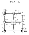
- FIG. 1 a first embodiment of the present invention will be explained.
- the oscillating body 1 which is suspended from a building 01 by cables 1a and 1b in the manner of a multistage pendulum; and a hole is bored on the bottom of the oscillating body 1; and a sliding member 9 is placed in the bored hole 1c.
- the bored hole 1c may also penetrate the oscillating body 1, if desired.
- a material with small friction coefficients or a slide shoe 11 is disposed at the slide mechanism between the oscillating body 1 and the sliding jig 9.
- the lower end of the sliding jig 9 is connected to a slider 2 through a universal joint or a ball joint 10.
- Beams 3 penetrate the slider 2 with an offset in the vertical direction so as to avoid each other and are arranged perpendicularly in a horizontal plane (as viewed from top).
- a material with small friction coefficients or a slide shoe 11 is also disposed at the sliding portions between the slider 2 and the beams 3.
- the nuts 4b of the ball screws 4 are attached to both ends of each beam 3, and the screw shafts 4a of the ball screws penetrate through and engage with the nuts.
- the screw shafts 4a of the ball screws 4 are supported by the building side through bearings 5.
- Gears 7 are disposed at one end of the screw shafts 4a and are in engagement with gears 7 disposed on a connection shaft 8.
- the connection shaft 8 is directly connected to a motor 6 so as to rotate.
- connection shaft 8 When the connection shaft 8 is driven by the motor 6 following instructions from a computer or a control device (not shown), the ball screws 4 are turned through the gears 7, and the nuts 4b in engagement with the ball screws 4 move in the direction of the ball screw 4.
- the beam 3 attached to the nuts 4b moves the slider 2, and in turn the slider 2 moves the oscillating body 1 through the universal or ball joint 10 and the sliding jig 9.
- This movement of the oscillating body is controlled to agree with the period of the building vibration with a phase shift of a half period.
- the energy of the reciprocating motion of the oscillating body cancels cut the vibrational energy of the building and thus reduces the building vibration.
- the oscillating body 1 moves up and down slightly as it moves in horizontal directions.
- Such vertical (up and down) motion is absorbed by the vertical sliding of the sliding jig 9.
- manufacturing errors of the multistage pendulum or the like may cause the rotational motion of the oscillating body 1 as it moves horizontally. This rotation can be absorbed by the universal or ball joint 10 at the lower end of the sliding jig 9.
- the drive in the two perpendicular directions has the same effects in all directions within the plane and functions in the same way because the slider 2 and the beams 3 slide in the respectable perpendicular directions.
- FIG. 2 shows a second embodiment of the present invention in which the sliding jig 9 in FIG. 1(a) is attached to the bottom side of the oscillating body 1.
- the sliding jig 9 is attached to the oscillating body 1 with a material having small friction coefficients or a slide shoe 11 and a cylindrical metal piece 12 to hold it.
- the slider 2 is connected to the universal or ball joint 10 at the lower end of the sliding jig 9 through a safety device 13 which breaks under certain load. When abnormal loading occurs due to malfunction or some disorders, the oscillating body 1 is cut off from the slider 2, so that the driving system is protected.
- This safety device 13 can also be placed between the metal piece 12 and the oscillating body 1. According to this embodiment, the bored hole 1c shown in FIG. 1(a) is not necessary, and the manufacturing therefore becomes advantageously simpler.
- FIG. 3 shows a third embodiment of the present invention in which the oscillating body 1 in FIG. 1(a) is directly connected to the slider 2, and the vertical (up and down) motion and the inclination of the oscillating body 1 can be absorbed by vertical sliding mechanisms disposed between the ends of beams 3 and the nut portion 4b of the ball screws 4.
- Numeral 14 indicates a slide guide which is a part of the sliding mechanism
- numeral 15 indicates a rail in the sliding mechanism.
- Numeral 20 indicates a slide for absorbing variations in the length of the beam 3 which occur when the beam 3 inclines along with the inclination of the oscillating body 1.
- a plurality of the slide guides 14 and the rails 15 can also be disposed at each end of the beam 3.
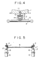
- FIG. 4 shows a fourth embodiment of the present invention in which the slider 2 does not slide directly around the beams 3 as in FIG. 1(a); instead, a slide guide 14 attached to the slider 2 slides on a rail 15 attached to the beam 3.
- the beam 3 because the beam 3 does not penetrate the slider 2 and is on the outside of the slider 2, the beam 3 can be made larger in the case where large driving forces are required.
- a plurality of slide guides 14 and rails 15 can be attached for each driving direction.
- FIG. 5 shows a fifth embodiment of the present invention in which two motors 6 are used to drive the ball screws 4 in FIG. 1(b) for each direction.
- the motors 6 drive the ball screw 4 through a speed increasing (or reducing) device 16 and through a torque limiter 17 which slips with excessive torques for protecting the driving system.
- the connection shaft 8 can be eliminated if the ball screws 4 on the two sides are synchronized sufficiently with each other.
- the number of the motors 6 can also be increased further for a plurality of motor to drive one ball screw 4.
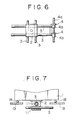
- FIG. 6 shows a sixth embodiment of the present invention in which two sets of the nuts are disposed at only one end of the beams for each driving direction instead of disposing one set on each end of the beam 3 as in FIG. 1(b). According to this embodiment, the number of the screw shafts can be reduced.
- FIG. 7 shows a seventh embodiment of the present invention in which, instead of being suspended in the manner of a multistage pendulum, the oscillating body 1 in FIG. 3(a) is placed on a base 19 fixed to a building by way of balls 18 so that the body can reciprocate in any direction in a horizontal plane.
- the construction can be advantageously simpler.
- the oscillating body 1 can be driven in a reciprocating manner so as to correspond to the vibration of the building in any horizontal direction.
- the vibrational energy of the building can be cancelled by the input energy, so that building vibrations can advantageously be reduced.
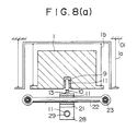
- FIG. 8 is a vertical sectional view of the eighth embodiment of the present invention, and (b) is a lower plan view of (a).
- the oscillating body 1 which is suspended as a multistage pendulum by cables 1a and 1b from a building 01 makes large amplitude reciprocating motions in horizontal directions, and it also moves slightly in the vertical direction.
- a slide shoe 11 is disposed between the oscillating body 1 and a sliding jig 9 for a slider 21 which will be explained below, so that the sliding jig 9 can move vertically, allowing for the vertical motion of the oscillating body 1.
- a safety device 13 is attached to the sliding jig 9 through a universal joint or a ball joint 10, so that the oscillating body can be cut off from the driving system in response to abnormal loading which occurs when the oscillating body makes abnormal motion due to malfunction or some other disorders. It is through this safety device 13 that a slider 21 for movable connection to ball screws 25 etc. described below is attached.
- a slide bar 22 penetrates the slider 21, and a slide shoe is provided in between so that the slide bar 22 can slide smoothly.
- a ball bearing 23 is provided in the hole at each end of the slide bar 22, and a bush 24 whose one end is a bevel gear is inserted into the inner ring of each ball bearing 23.
- a nut 25b of the ball screw 25 is inserted inside the bush 24. This nut 25b is penetrated by and in engagement with the screw shaft 25a of the ball screw 25 whose ends are fixed to the building 01 through support bases 35.
- the bevel gear of the bush 24 is driven to rotate by a gear shaft 27 which is in turn driven by a mechanism including a pinion gear 32 which is powered by a motor 26 attached to the slide bar 22 within the same horizontal plane.
- the nut 25b rotates together with the bush 24, and the oscillating body 1 moves in the vertical (up and down) direction in FIG. 8(b).
- the gear shaft 27 is supported by gear shaft bearings 33.
- Another slider 28 is provided under the slider 21 as shown in FIG. 8(b).
- This slider 28 is provided for moving the oscillating body 1 in the direction perpendicular with respect to the slider 21.
- a slide bar 29 is inserted through the slider 28 with a slide shoe 11 between the slide bar 29 and the slider 28.
- the nut 30b of the ball screw 30 is fixed to each end of the slide bar 29.
- This nut 30b is penetrated by and in engagement with the screw shaft 30a of the ball screws 30 which are supported by the building 01 by way of a bearing 34.
- the screw shafts 30a are driven to rotate by a motor 31 which is fixed to the building 01 by some suitable means.
- the nut 30b moves with the slide bar 29 and moves the oscillating body 1 in the left and right direction in FIG. 8(b).
- the nut 25b rotates with respect to the screw shaft 25a which is fixed.
- the screw shaft 30a rotates with respect to the nut 30b.
- the oscillating body 1 moves in any direction which is the vertical or the horizontal direction or an arbitrary combination of the vertical and horizontal directions of FIG. 8(b).
- the oscillating body 1 can be moved as a pendulum in an arbitrary direction with the ball screws 25 and 30. By synchronizing this motion with the vibration of the building 01 in the most suitable manner, the vibration of the building in any direction can be advantageously reduced.
- the oscillating body held so as to move in horizontal directions is driven in two perpendicular directions by ball screws which are powered by motors, the oscillating body can move in any direction, and building vibrations in any horizontal direction can be reduced effectively.
- FIGS. 11 to 14 we shall describe a ninth embodiment of the present invention.
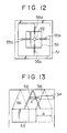
- Numeral 51 indicates an outer frame comprising an upper frame 51a and a rectangular pillar 51b. From the upper frame 51a of the outer frame 51, the oscillating body 53 with a rectangular horizontal section is suspended by four wires 56. The center portion of the upper side of the oscillating body 53 and the upper frame 51a of the outer frame are connected to each other by way of the rod 52. The upper and lower ends of the rod 52 are connected to the upper frame 51a of the outer frame and to the upper side of the oscillating body 53, respectively, by way of joints 57a, 57b which do not restrict the motion and rotation of the oscillating body 53 in any direction and which do not support the weight of the oscillating body 53.
- each shock absorber 54 as damping elements and the springs 55 are disposed horizontally in two perpendicular directions. Both ends of each shock absorber 54 and each spring 55 are connected to the rod 52 and the pillar 51b of the outer frame through joints 58a, 58b, respectively. Also, of the springs 55, the two sets of the springs 55a, 55b arranged perpendicularly to each other can be adjusted independently of each other, so that they can correspond to the different natural frequency of the respective direction.
- the shock absorbers 54 and the springs 55 are attached to the rod 52 which is connected to the center of the oscillating body 53 while shock absorbers 54 are attached to the side of the oscillating body in the conventional pendulum type dynamic damper, the occupied area can be reduced.
- the length L of the outer frame of this embodiment and the length L ′ of the outer frame of the conventional pendulum type dynamic damper are shown in FIGS. 14 and 15.
- the rod 52 does not restrict the motion of the oscillating body 53 and connects the oscillating body 53 and the upper frame 51a of the outer frame without supporting the weight of the oscillating body 53, the damping effects by the shock absorbers 54 and the springs 55 can be achieved effectively. Further, because as shown in FIG. 13, the total displacement (twice the amplitude) A ′ of oscillation for the shock absorbers 54 and the springs 55 remains small compared to the total displacement A of the oscillating body 53, the required strokes of the shock absorbers 54 and the springs 55 can be smaller, and the design of these would be easier.
- the oscillating body 53 in this embodiment does not rotate unlike an inverted pendulum and moves in a more or less linear fashion. Thus it is easier to adapt to the dynamic control of the oscillating body 53 in a horizontal plane using active dynamic dampers or the like.
- the present invention achieves the following effects.
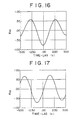
- FIG. 16 is a graph showing a normal relation of the correlation R xy between the acceleration of the building and the torque of the motor
- FIG. 17 is a graph showing the case in which the damping performance is somewhat degraded
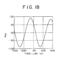
- FIG. 18 is a graph showing the case in which the dynamic damper is malfunctioning.
- the correlation R xy can be obtained by the following equation: where X(t) is the acceleration of the building, and Y(t) is the torque of the motor.
- the maximum value of building acceleration is 19.1 gal. This means an increase over 17.0 gal without damping.
- a setup required in reducing into practice the method of present invention as described above consists of a sensor for detecting the vibration of the building, a torque meter for motors, and an analyzer. Thus it is not necessary to install these instruments permanently. They can be attached at the time of inspection. Also, it is possible to use one set of these instruments for a plurality of dynamic dampers, making inspection more economical.
- the method of the present invention is totally independent of the control apparatus, it has high reliability and is safe to use.
Landscapes
- Engineering & Computer Science (AREA)
- Architecture (AREA)
- General Engineering & Computer Science (AREA)
- Business, Economics & Management (AREA)
- Emergency Management (AREA)
- Environmental & Geological Engineering (AREA)
- Mechanical Engineering (AREA)
- Civil Engineering (AREA)
- Structural Engineering (AREA)
- Vibration Prevention Devices (AREA)
- Buildings Adapted To Withstand Abnormal External Influences (AREA)
- Transmission Devices (AREA)
Abstract

Description
- The present invention relates to a dynamic damper for reducing the vibrations of buildings or structures or the like. The present invention also relates to a method for detecting malfunction of a dynamic damper which is used in buildings or the like.
- As conventional dynamic dampers which are disposed in a building or the like and in which an oscillating body is driven for reducing the oscillations and vibrations of the building where this damper is placed, dynamic dampers have been known in which an oscillating body 1 supported by
wheels 42 onrails 41 is driven to reciprocate using acylinder type shaker 43 as shown in FIG. 9 or in which the rotation of amotor 44 is transformed into reciprocating linear motion using arack 45a and apinion 45b as shown in FIG. 10. - Furthermore, as shown in FIG. 15, a conventional pendulum type dynamic damper is characterized in that a oscillating
body 63 is suspended from anouter frame 61 by way of a plurality of cables orwires 66, and shock absorbers 64 as damping elements is disposed horizontally between two sides of the oscillatingbody 63 and theouter frame 61. - Also, a variety of methods, such as judging a disorder when two or three parallel systems of control circuits transmit different signals, and giving instructions based on decision by majority, have conventionally been known for detecting malfunction of a dynamic damper.
- The above-mentioned conventional dynamic dampers have the following problems.
- In order to reduce vibrations in all horizontal directions, the oscillating body has to be driven in two directions. The vibration reduction effect of the conventional dynamic damper, however, is restricted to the direction of the rail and the rack used, i.e., to a single direction.
- In the conventional damper, such as the one shown in FIG. 15, because the damping elements are attached to the side of the oscillating body whose amplitude of oscillation is large, and because its required space has to include the size of the oscillating body, its amplitude of oscillation, the length of the damping elements, and its stroke, a large space is required for the disposition of the damping system. In addition, the stroke of the damping elements has to be large.
- Also, because the conventional pendulum type damper has a frequency which is determined by the suspension length of the wires, if the natural frequency of a building is very much different in two perpendicular directions, it has been difficult to adapt the conventional damper to such a building.
- Although there exist inverted pendulum type dynamic dampers in order to solve this problem, because the trajectory of motion of the oscillating body is an arc, it has been difficult to control the motion of the oscillating body in a horizontal plane, for example, in the case of adapting it to an active dynamic damper.
- Also, the conventional methods for detecting malfunction of a dynamic damper described above has a problem of high costs.
- An object of the present invention is to provide a dynamic damper which can cope with building vibrations in any horizontal direction and which solves the above problems associated with the conventional dynamic dampers.
- Another object of the present invention is to provide an economical method for detecting malfunction of a dynamic damper which does not cost too much and can be, if desired, used only during inspection without permanent installation.
- The present invention provides a dynamic damper which comprises an oscillating body which is held to move horizontally with respect to a building whose vibration is to be reduced, a plurality of ball screws which are arranged perpendicularly to each other with a height difference among them and which have a nut portion on the side of the oscillating body and a screw shaft engaging with said nut portion on the side of the building, and motors which reciprocate the oscillating body according to the period of vibration of the building by turning the ball screws.
- The reciprocating motion of the oscillating body and the vibration of a building can be synchronized because the nuts of the ball screws are disposed on the side of the oscillating body which is held so as to move horizontally with respect to the building, and screw shafts and a motor are disposed in the building side so that the ball screws turn and the oscillating body reciprocates in keeping with the vibrational period of the building. By shifting the phase between the vibration of the building and the reciprocating motion of the oscillating body, the vibration of the building is reduced. Vibrations in any direction within the plane can be reduced because a plurality of the ball screws are arranged in perpendicular directions.
- The present invention also provides a dynamic damper which comprises an oscillating body which is held so as to move horizontally with respect to a building whose vibration is to be reduced, ball screws which are arranged horizontally under the oscillating body and whose screw shafts are fixed at their ends to the building and whose nuts are supported by the oscillating body so that the nuts can be rotated by a motor and so as to restrict the nuts' motion in their axial direction, and another set of ball screws which are arranged horizontally so that the two sets of ball screws are arranged perpendicularly as viewed from top and whose screw shafts are supported by the building so that the shafts can be rotated by a motor and whose nuts are supported by the oscillating body so as to restrict the nuts' rotation and motion in their axial direction with respect to the oscillating body.
- To the oscillating body which is held by a building so that it can move horizontally, the ball screws are arranged horizontally in two perpendicular directions; the nuts are supported so that their motion is restricted in their axial direction with respect to the oscillating body; the screw shafts of one set of the ball screws are fixed to the building and their nuts are held so as to be rotated by a motor; and the screw shafts of the other set of ball screws are fixed to the building so that the screw shafts are rotated by a motor. When the motors turn in correspondence with the vibration of the building the oscillating body makes a reciprocating movement similar to the vibration of the building. By synchronizing the motion of the oscillating body with a phase shift of a half period, the vibrational energy of the building and the kinetic energy of the oscillating body cancel each other out, and the vibration of the building is reduced drastically.
- Furthermore, the present invention provides another dynamic damper which comprises a oscillating body which is suspended from an outer frame, a rod for connecting the oscillating body and the upper portion of the outer frame without restricting the motion of the oscillating body and without supporting the weight of the oscillating body, and springs and damping elements which are disposed more or less horizontally between the outer frame and the rod.
- According to this dynamic damper of the present invention, the oscillating body which is suspended from the outer frame is connected to an upper frame of the outer frame by way of the rod without the rod's supporting the weight of the oscillating body and without restricting the motion of the oscillating body. Thus damping effects are achieved because of the damping elements and the springs connecting the oscillating body and the rod to the outer frame.
- Because the springs and the damping elements are disposed between the rod and the outer frame, the required area (or the occupied space) can be reduced compared to the case in which the damping elements are disposed between the side walls of the oscillating body and the outer frame as in the conventional dynamic damper described above. Also, the stroke of the damping elements etc. can be smaller compared to the conventional dynamic damper, in which the damping elements are attached to the sides of the oscillating body, and in which the operation of the damping elements is directly linked with the motion of the oscillating body with respect to the outer frame. Thus the designing and manufacture become easier.
- In addition, because the springs are used as well as the damping elements, it is possible to adapt the dynamic damper to buildings with different natural frequencies by changing the stiffness of the springs.
- Further, the oscillating body does not show rotational motion unlike an inverted pendulum type dynamic damper, and its oscillational motion can be close to being linear. This makes it easier to control the motion of the oscillating body in a horizontal plane using, for example, active damping.
- The present invention also provides a method for detecting malfunction of a dynamic damper which comprises the steps of finding the correlation R xy between the acceleration or velocity or displacement of the building whose vibration is to be reduced and the driving force of the dynamic damper, and judging whether or not malfunction has occurred based on whether the value of the above correlation R xy at a time-lag s = 0 is on the positive or the negative side and/or based on the value of the time-lag s which corresponds to a minimum of the correlation R xy on the negative side.
- According to this method of the present invention, it can be judged whether the dynamic damper is functioning to reduce the vibration of the object building or it is rather increasing the vibration of the object building due to disorders in computers or the like.
-
- FIG. 1 shows a first embodiment of the present invention; (a) is a sectional view and (b) is a sectional plan view, viewed as indicated by the arrows b-b in (a);
- FIG. 2 shows a second embodiment of the present invention in correspondence with FIG. 1(a);
- FIG. 3 shows a third embodiment of the present invention which corresponds to FIG. 1(a); (b) is a sectional plan view, viewed as indicated by the arrows b-b in (a);
- FIG. 4 shows a fourth embodiment of the present invention in correspondence with FIG. 1(a);
- FIG. 5 shows a fifth embodiment of the present invention in correspondence with to FIG. 1(b);
- FIG. 6 shows a sixth embodiment of the present invention in correspondence with FIG. 1(b);
- FIG. 7 shows a seventh embodiment of the present invention in correspondence with FIG. 3(a);
- FIG. 8 shows an eighth embodiment of the present invention; (a) is its sectional view, and (b) is its lower plan view;
- FIG. 9 shows a side view of a conventional example;
- FIG. 10 shows a side view of another conventional example;
- FIG. 11 shows a ninth embodiment of the dynamic damper of the present invention;
- FIG. 12 shows a plan view of this embodiment;
- FIG. 13 shows the amplitudes and strokes of the oscillating body and the shock absorbers and the like;
- FIG. 14 shows the effect of this embodiment on the occupied space;
- FIG. 15 shows a conventional pendulum type dynamic damper;
- FIG. 16 shows a normal relation between the acceleration of the building and the motor torque which is an application of the present invention to the buffeting vibration of a building due to the variation of wind velocity;
- FIG. 17 shows the case in which the performance of the dynamic damper is somewhat degraded; and
- FIG. 18 shows an example of abnormal operation of the dynamic damper.
- Referring to FIG. 1, a first embodiment of the present invention will be explained.
- In this drawing, the oscillating body 1 which is suspended from a building 01 by cables 1a and 1b in the manner of a multistage pendulum; and a hole is bored on the bottom of the oscillating body 1; and a sliding member 9 is placed in the bored hole 1c. The bored hole 1c may also penetrate the oscillating body 1, if desired. A material with small friction coefficients or a
slide shoe 11 is disposed at the slide mechanism between the oscillating body 1 and the sliding jig 9. The lower end of the sliding jig 9 is connected to aslider 2 through a universal joint or aball joint 10.Beams 3 penetrate theslider 2 with an offset in the vertical direction so as to avoid each other and are arranged perpendicularly in a horizontal plane (as viewed from top). A material with small friction coefficients or aslide shoe 11 is also disposed at the sliding portions between theslider 2 and thebeams 3. The nuts 4b of the ball screws 4 are attached to both ends of eachbeam 3, and thescrew shafts 4a of the ball screws penetrate through and engage with the nuts. Thescrew shafts 4a of the ball screws 4 are supported by the building side throughbearings 5.Gears 7 are disposed at one end of thescrew shafts 4a and are in engagement withgears 7 disposed on aconnection shaft 8. Theconnection shaft 8 is directly connected to amotor 6 so as to rotate. - When the
connection shaft 8 is driven by themotor 6 following instructions from a computer or a control device (not shown), the ball screws 4 are turned through thegears 7, and the nuts 4b in engagement with the ball screws 4 move in the direction of theball screw 4. At the same time, thebeam 3 attached to the nuts 4b moves theslider 2, and in turn theslider 2 moves the oscillating body 1 through the universal or ball joint 10 and the sliding jig 9. This movement of the oscillating body is controlled to agree with the period of the building vibration with a phase shift of a half period. As a result, the energy of the reciprocating motion of the oscillating body cancels cut the vibrational energy of the building and thus reduces the building vibration. In this embodiment of the present invention, because it is suspended as a multistage pendulum, the oscillating body 1 moves up and down slightly as it moves in horizontal directions. Such vertical (up and down) motion is absorbed by the vertical sliding of the sliding jig 9. Also, manufacturing errors of the multistage pendulum or the like may cause the rotational motion of the oscillating body 1 as it moves horizontally. This rotation can be absorbed by the universal or ball joint 10 at the lower end of the sliding jig 9. - Also, the drive in the two perpendicular directions has the same effects in all directions within the plane and functions in the same way because the
slider 2 and thebeams 3 slide in the respectable perpendicular directions. - FIG. 2 shows a second embodiment of the present invention in which the sliding jig 9 in FIG. 1(a) is attached to the bottom side of the oscillating body 1. The sliding jig 9 is attached to the oscillating body 1 with a material having small friction coefficients or a
slide shoe 11 and acylindrical metal piece 12 to hold it. In this embodiment, theslider 2 is connected to the universal or ball joint 10 at the lower end of the sliding jig 9 through asafety device 13 which breaks under certain load. When abnormal loading occurs due to malfunction or some disorders, the oscillating body 1 is cut off from theslider 2, so that the driving system is protected. Thissafety device 13 can also be placed between themetal piece 12 and the oscillating body 1. According to this embodiment, the bored hole 1c shown in FIG. 1(a) is not necessary, and the manufacturing therefore becomes advantageously simpler. - FIG. 3 shows a third embodiment of the present invention in which the oscillating body 1 in FIG. 1(a) is directly connected to the
slider 2, and the vertical (up and down) motion and the inclination of the oscillating body 1 can be absorbed by vertical sliding mechanisms disposed between the ends ofbeams 3 and thenut portion 4b of the ball screws 4.Numeral 14 indicates a slide guide which is a part of the sliding mechanism, and numeral 15 indicates a rail in the sliding mechanism.Numeral 20 indicates a slide for absorbing variations in the length of thebeam 3 which occur when thebeam 3 inclines along with the inclination of the oscillating body 1. A plurality of the slide guides 14 and therails 15 can also be disposed at each end of thebeam 3. - FIG. 4 shows a fourth embodiment of the present invention in which the
slider 2 does not slide directly around thebeams 3 as in FIG. 1(a); instead, aslide guide 14 attached to theslider 2 slides on arail 15 attached to thebeam 3. In this embodiment, because thebeam 3 does not penetrate theslider 2 and is on the outside of theslider 2, thebeam 3 can be made larger in the case where large driving forces are required. Also, a plurality of slide guides 14 and rails 15 can be attached for each driving direction. - FIG. 5 shows a fifth embodiment of the present invention in which two
motors 6 are used to drive the ball screws 4 in FIG. 1(b) for each direction. In this embodiment, themotors 6 drive theball screw 4 through a speed increasing (or reducing)device 16 and through atorque limiter 17 which slips with excessive torques for protecting the driving system. Also, theconnection shaft 8 can be eliminated if the ball screws 4 on the two sides are synchronized sufficiently with each other. Furthermore, the number of themotors 6 can also be increased further for a plurality of motor to drive oneball screw 4. - FIG. 6 shows a sixth embodiment of the present invention in which two sets of the nuts are disposed at only one end of the beams for each driving direction instead of disposing one set on each end of the
beam 3 as in FIG. 1(b). According to this embodiment, the number of the screw shafts can be reduced. - FIG. 7 shows a seventh embodiment of the present invention in which, instead of being suspended in the manner of a multistage pendulum, the oscillating body 1 in FIG. 3(a) is placed on a base 19 fixed to a building by way of
balls 18 so that the body can reciprocate in any direction in a horizontal plane. According to this embodiment, the construction can be advantageously simpler. - We have described the seven embodiments in which the oscillating body 1 is suspended by cables 1a and 1b as a multistage pendulum, or it is placed on the
balls 18. The method of holding the oscillating body 1, however, is by no means restricted to the above two examples of suspension. Any means which does not go against the objects of the present invention can be used as well. - As we have seen above, according to the first to seventh embodiments of the present invention, the oscillating body 1 can be driven in a reciprocating manner so as to correspond to the vibration of the building in any horizontal direction. By synchronizing the motion of the oscillating body with the building vibration with a suitable phase shift, the vibrational energy of the building can be cancelled by the input energy, so that building vibrations can advantageously be reduced.
- An eighth embodiment of the present invention will now be explained, referring to FIG. 8. In FIG. 8, (a) is a vertical sectional view of the eighth embodiment of the present invention, and (b) is a lower plan view of (a).
- In FIG. 8, the oscillating body 1 which is suspended as a multistage pendulum by cables 1a and 1b from a building 01 makes large amplitude reciprocating motions in horizontal directions, and it also moves slightly in the vertical direction. Thus a
slide shoe 11 is disposed between the oscillating body 1 and a sliding jig 9 for aslider 21 which will be explained below, so that the sliding jig 9 can move vertically, allowing for the vertical motion of the oscillating body 1. Also, asafety device 13 is attached to the sliding jig 9 through a universal joint or a ball joint 10, so that the oscillating body can be cut off from the driving system in response to abnormal loading which occurs when the oscillating body makes abnormal motion due to malfunction or some other disorders. It is through thissafety device 13 that aslider 21 for movable connection to ball screws 25 etc. described below is attached. - A
slide bar 22 penetrates theslider 21, and a slide shoe is provided in between so that theslide bar 22 can slide smoothly. Aball bearing 23 is provided in the hole at each end of theslide bar 22, and abush 24 whose one end is a bevel gear is inserted into the inner ring of eachball bearing 23. Anut 25b of theball screw 25 is inserted inside thebush 24. Thisnut 25b is penetrated by and in engagement with thescrew shaft 25a of theball screw 25 whose ends are fixed to the building 01 through support bases 35. The bevel gear of thebush 24 is driven to rotate by agear shaft 27 which is in turn driven by a mechanism including apinion gear 32 which is powered by amotor 26 attached to theslide bar 22 within the same horizontal plane. Thus thenut 25b rotates together with thebush 24, and the oscillating body 1 moves in the vertical (up and down) direction in FIG. 8(b). Thegear shaft 27 is supported bygear shaft bearings 33. - Another
slider 28 is provided under theslider 21 as shown in FIG. 8(b). Thisslider 28 is provided for moving the oscillating body 1 in the direction perpendicular with respect to theslider 21. Aslide bar 29 is inserted through theslider 28 with aslide shoe 11 between theslide bar 29 and theslider 28. Thenut 30b of theball screw 30 is fixed to each end of theslide bar 29. Thisnut 30b is penetrated by and in engagement with thescrew shaft 30a of the ball screws 30 which are supported by the building 01 by way of abearing 34. Thescrew shafts 30a are driven to rotate by amotor 31 which is fixed to the building 01 by some suitable means. As a result, thenut 30b moves with theslide bar 29 and moves the oscillating body 1 in the left and right direction in FIG. 8(b). - In regard to the
ball screw 25, thenut 25b rotates with respect to thescrew shaft 25a which is fixed. In regard to theball screw 30, as thescrew shaft 30a rotates with respect to thenut 30b. Thus the oscillating body 1 moves in any direction which is the vertical or the horizontal direction or an arbitrary combination of the vertical and horizontal directions of FIG. 8(b). - By adjusting this direction of motion to the direction of vibration of the building 01, and by controlling the speed and the rotational direction of the
motors slide shoe 11 as explained above. - As we have described above, according to this embodiment, the oscillating body 1 can be moved as a pendulum in an arbitrary direction with the ball screws 25 and 30. By synchronizing this motion with the vibration of the building 01 in the most suitable manner, the vibration of the building in any direction can be advantageously reduced.
- Also, the mechanisms described in the second to fifth embodiments as well as in the seventh embodiment above can be used equally well in combination with this eighth embodiment.
- Because the oscillating body held so as to move in horizontal directions is driven in two perpendicular directions by ball screws which are powered by motors, the oscillating body can move in any direction, and building vibrations in any horizontal direction can be reduced effectively.
- Referring to FIGS. 11 to 14, we shall describe a ninth embodiment of the present invention.
-
Numeral 51 indicates an outer frame comprising an upper frame 51a and a rectangular pillar 51b. From the upper frame 51a of theouter frame 51, theoscillating body 53 with a rectangular horizontal section is suspended by fourwires 56. The center portion of the upper side of theoscillating body 53 and the upper frame 51a of the outer frame are connected to each other by way of therod 52. The upper and lower ends of therod 52 are connected to the upper frame 51a of the outer frame and to the upper side of theoscillating body 53, respectively, by way ofjoints oscillating body 53 in any direction and which do not support the weight of theoscillating body 53. Four sets in total of theshock absorbers 54 as damping elements and thesprings 55 are disposed horizontally in two perpendicular directions. Both ends of eachshock absorber 54 and eachspring 55 are connected to therod 52 and the pillar 51b of the outer frame throughjoints springs 55, the two sets of thesprings - In the embodiment of the present invention described above, because the
shock absorbers 54 and thesprings 55 are attached to therod 52 which is connected to the center of theoscillating body 53 whileshock absorbers 54 are attached to the side of the oscillating body in the conventional pendulum type dynamic damper, the occupied area can be reduced. For comparison, the length L of the outer frame of this embodiment and the length L′ of the outer frame of the conventional pendulum type dynamic damper are shown in FIGS. 14 and 15. - Also, in this embodiment, because the
rod 52 does not restrict the motion of theoscillating body 53 and connects theoscillating body 53 and the upper frame 51a of the outer frame without supporting the weight of theoscillating body 53, the damping effects by theshock absorbers 54 and thesprings 55 can be achieved effectively. Further, because as shown in FIG. 13, the total displacement (twice the amplitude) A′ of oscillation for theshock absorbers 54 and thesprings 55 remains small compared to the total displacement A of theoscillating body 53, the required strokes of theshock absorbers 54 and thesprings 55 can be smaller, and the design of these would be easier. - In addition, according to this embodiment, by changing the stiffness of the
springs 55 or changing the stiffness of the two sets ofsprings - Furthermore, the
oscillating body 53 in this embodiment does not rotate unlike an inverted pendulum and moves in a more or less linear fashion. Thus it is easier to adapt to the dynamic control of theoscillating body 53 in a horizontal plane using active dynamic dampers or the like. - Also, while in the above-described embodiment, four sets of shock absorbers and springs are arranged in two perpendicular directions, other arrangements of springs and shock absorbers are possible within the scope of the present invention. For example, only two sets of shock absorbers and springs can be arranged in one direction, facing each other.
- Because the oscillating body suspended from the outer frame is connected to the upper frame of the outer frame by the rod without the rod's supporting the weight of the oscillating body and without restricting the motion of the oscillating body, and because the damping elements and the springs are disposed horizontally to connect the rod and the outer frame, the present invention achieves the following effects.
- (1) The area occupied by the dynamic damper can be reduced.
- (2) The strokes of the damping elements and the springs can be reduced, making the designing and the manufacture of a dynamic damper easier.
- (3) By changing the stiffness of the springs, the dynamic damper of the present invention can be adapted to objects with different natural frequencies.
- (4) The oscillating body does not rotate, and the dynamic control of the motion of the oscillating body becomes easily possible in a horizontal plane.
- Referring to FIGS. 16 to 18, we will describe an embodiment of the method of the present invention adapted to the damping of buffeting vibration of a building due to variations in wind velocity. FIG. 16 is a graph showing a normal relation of the correlation R xy between the acceleration of the building and the torque of the motor, FIG. 17 is a graph showing the case in which the damping performance is somewhat degraded, and FIG. 18 is a graph showing the case in which the dynamic damper is malfunctioning.
- Here, the correlation Rxy can be obtained by the following equation:

- In FIG. 16, when the dynamic damper is functioning properly, the maximum response of acceleration of the building is reduced to 7.2 gal from 17.0 gal without damping.
- If the performance of the dynamic damper is degraded somewhat as shown in FIG. 17, the maximum acceleration of the building is 11.1 gal.
- If the dynamic damper functions as a shaker due to some malfunction of the dynamic damper system, the maximum value of building acceleration is 19.1 gal. This means an increase over 17.0 gal without damping.
- If we look at the correlation R xy at s (time-lag) = 0, R xy ≈ -0.75 in FIG. 16, R xy ≈ -0.15 in FIG. 17, R xy ≈ 0.5 in FIG. 18. When the correlation at s = 0 is on the positive side, the condition of the apparatus can be judged to have become abnormal.
- Also, if we look at the values of time-lag s at which the correlation R xy takes negative minimum values, s = 0.0 in FIG. 16, s = -1.0 sec in FIG. 17, s = -3.5 sec in FIG. 18. In these examples, if this s is less than -1.5 to -2.0, it can be judged that some malfunction has occurred in the apparatus.
- A setup required in reducing into practice the method of present invention as described above consists of a sensor for detecting the vibration of the building, a torque meter for motors, and an analyzer. Thus it is not necessary to install these instruments permanently. They can be attached at the time of inspection. Also, it is possible to use one set of these instruments for a plurality of dynamic dampers, making inspection more economical.
- Furthermore, because the method of the present invention is totally independent of the control apparatus, it has high reliability and is safe to use.
- According to the method the present invention, the correlation R xy between the acceleration or velocity or displacement of a building whose vibration is to be reduced and the driving force of a dynamic damper is obtained, and whether or not malfunction has occurred is judged based on whether the value of the above correlation R xy at s = 0 is on the positive or the negative side and/or based on the value of the time-lag s corresponding to the minimum of R xy on the negative side. Therefore, the method of the present invention is economical and can be, if desired, reduced to working without permanent installment. Thus the present invention is very useful in industrial applications.
Claims (4)
Applications Claiming Priority (8)
| Application Number | Priority Date | Filing Date | Title |
|---|---|---|---|
| JP269019/89 | 1989-10-18 | ||
| JP1269019A JP2706331B2 (en) | 1989-10-18 | 1989-10-18 | Damping device |
| JP270203/89 | 1989-10-19 | ||
| JP1270203A JP2670157B2 (en) | 1989-10-19 | 1989-10-19 | Damping device |
| JP2037800A JP2680712B2 (en) | 1990-02-19 | 1990-02-19 | Vibration control device malfunction detection method |
| JP37800/90 | 1990-02-19 | ||
| JP10538090A JPH044335A (en) | 1990-04-23 | 1990-04-23 | Pendulum type vibration damping device |
| JP105380/90 | 1990-04-23 |
Publications (3)
| Publication Number | Publication Date |
|---|---|
| EP0428239A2 true EP0428239A2 (en) | 1991-05-22 |
| EP0428239A3 EP0428239A3 (en) | 1991-08-21 |
| EP0428239B1 EP0428239B1 (en) | 1995-04-19 |
Family
ID=27460470
Family Applications (1)
| Application Number | Title | Priority Date | Filing Date |
|---|---|---|---|
| EP90250252A Expired - Lifetime EP0428239B1 (en) | 1989-10-18 | 1990-10-04 | Dynamic damper and method for detecting malfunction of a dynamic damper |
Country Status (7)
| Country | Link |
|---|---|
| US (1) | US5168967A (en) |
| EP (1) | EP0428239B1 (en) |
| AU (1) | AU629405B2 (en) |
| CA (1) | CA2026351C (en) |
| DE (1) | DE69018774T2 (en) |
| HK (1) | HK12897A (en) |
| NZ (1) | NZ235423A (en) |
Cited By (8)
| Publication number | Priority date | Publication date | Assignee | Title |
|---|---|---|---|---|
| FR2698896A1 (en) * | 1992-12-09 | 1994-06-10 | Oudin Gilles | Device to prevent oscillation of tall structures - has inert mass attached to structure by elastic components and shock-absorbing cable springs which can be regulated |
| EP2730709A1 (en) * | 2012-11-13 | 2014-05-14 | Wölfel Beratende Ingenieure GmbH & Co. KG | Vibration absorber assembly |
| CN105402309A (en) * | 2015-11-16 | 2016-03-16 | 浙江大学 | Cultural relic shock-proof device adopting hybrid shock-absorbing technology |
| CN106594170A (en) * | 2016-11-08 | 2017-04-26 | 浙江大学 | Active-passive hybrid seismic control method for cultural relic and free-standing platform |
| CN109779062A (en) * | 2019-03-07 | 2019-05-21 | 重庆恩倍克科技有限公司 | A kind of damper for building |
| CN110514125A (en) * | 2019-09-30 | 2019-11-29 | 西南石油大学 | A kind of double steel disc bridge displacement monitoring methods |
| CN110700429A (en) * | 2019-09-19 | 2020-01-17 | 西安工程大学 | SMA composite universal suspension damping device |
| CN110725557A (en) * | 2019-09-19 | 2020-01-24 | 西安工程大学 | SMA (shape memory alloy) composite suspended pendulum damping device for historical buildings |
Families Citing this family (15)
| Publication number | Priority date | Publication date | Assignee | Title |
|---|---|---|---|---|
| JP2546465B2 (en) * | 1992-01-28 | 1996-10-23 | 鹿島建設株式会社 | Vibration control device for structures |
| JP2610243B2 (en) * | 1994-03-08 | 1997-05-14 | 有限会社新技研 | Structure damping method |
| US6115972A (en) * | 1996-04-09 | 2000-09-12 | Tamez; Federico Garza | Structure stabilization system |
| JP2001214633A (en) * | 2000-02-04 | 2001-08-10 | Hitachi Metals Techno Ltd | Cushioning device for building and its monitor system and control system |
| WO2004053247A1 (en) * | 2002-12-09 | 2004-06-24 | Sanders Design International, Inc. | Siesmic sensitive mass motion power converter for protecting structures from earthquakes |
| DE102010015160B4 (en) * | 2010-04-16 | 2012-02-23 | Wölfel Beratende Ingenieure GmbH & Co. KG | Tower vibration damper for a wind turbine and wind turbine |
| TWI405914B (en) * | 2010-12-10 | 2013-08-21 | Univ Nat Taiwan Science Tech | Dual-beam multiple frequency vibration absorber |
| CN102535674B (en) * | 2012-02-22 | 2014-01-22 | 广东电网公司电力科学研究院 | Tempering damper system used for improving wind resistance stability of transmission tower based on single pendulum model |
| CN103291799B (en) * | 2013-06-27 | 2017-08-25 | 无锡市宏源弹性器材有限公司 | Non-angular-displacevibration vibration isolation device with steel cable |
| JP6787643B2 (en) * | 2015-08-21 | 2020-11-18 | Thk株式会社 | Upper and lower seismic isolation device |
| JP6580457B2 (en) * | 2015-10-29 | 2019-09-25 | Thk株式会社 | Rotating inertia mass damper |
| CN107119958B (en) * | 2017-06-20 | 2022-05-10 | 大连理工大学 | Gear transmission amplification type node shear damper |
| CN112928971A (en) * | 2021-02-19 | 2021-06-08 | 唐山钢铁集团有限责任公司 | Wind-resistant shockproof photovoltaic support |
| CN113756462A (en) * | 2021-08-20 | 2021-12-07 | 北京工业大学 | Multiple gear drive particle inertial volume damper |
| CN114412261B (en) * | 2022-01-28 | 2023-05-09 | 湖南科技大学 | Multidimensional tuning mass damper for wind power generation tower |
Citations (4)
| Publication number | Priority date | Publication date | Assignee | Title |
|---|---|---|---|---|
| JPS5989849A (en) * | 1982-11-11 | 1984-05-24 | Mitsubishi Electric Corp | Vibration control device |
| JPS5997342A (en) * | 1982-11-26 | 1984-06-05 | Nippon Kokan Kk <Nkk> | Pendulum-type dynamic vibration absorber |
| US4525659A (en) * | 1981-10-20 | 1985-06-25 | Telmec Co., Ltd. | Positioning stage having a vibration suppressor |
| JPS6170243A (en) * | 1984-09-13 | 1986-04-11 | Mitsubishi Electric Corp | Vibration control device |
Family Cites Families (3)
| Publication number | Priority date | Publication date | Assignee | Title |
|---|---|---|---|---|
| SU1059323A2 (en) * | 1981-03-03 | 1983-12-07 | Центральный Ордена Трудового Красного Знамени Научно-Исследовательский Институт Строительных Конструкций Им.В.А.Кучеренко | Dynamic damper of pendular type oscillations |
| US4483425A (en) * | 1982-09-09 | 1984-11-20 | North American Philips Corporation | Vibration control system |
| JP2668990B2 (en) * | 1988-10-06 | 1997-10-27 | 石川島播磨重工業株式会社 | Structure damping device |
-
1990
- 1990-09-24 NZ NZ235423A patent/NZ235423A/en unknown
- 1990-09-27 CA CA002026351A patent/CA2026351C/en not_active Expired - Fee Related
- 1990-09-28 AU AU63713/90A patent/AU629405B2/en not_active Ceased
- 1990-10-01 US US07/591,554 patent/US5168967A/en not_active Expired - Lifetime
- 1990-10-04 DE DE69018774T patent/DE69018774T2/en not_active Expired - Fee Related
- 1990-10-04 EP EP90250252A patent/EP0428239B1/en not_active Expired - Lifetime
-
1997
- 1997-02-05 HK HK12897A patent/HK12897A/en not_active IP Right Cessation
Patent Citations (4)
| Publication number | Priority date | Publication date | Assignee | Title |
|---|---|---|---|---|
| US4525659A (en) * | 1981-10-20 | 1985-06-25 | Telmec Co., Ltd. | Positioning stage having a vibration suppressor |
| JPS5989849A (en) * | 1982-11-11 | 1984-05-24 | Mitsubishi Electric Corp | Vibration control device |
| JPS5997342A (en) * | 1982-11-26 | 1984-06-05 | Nippon Kokan Kk <Nkk> | Pendulum-type dynamic vibration absorber |
| JPS6170243A (en) * | 1984-09-13 | 1986-04-11 | Mitsubishi Electric Corp | Vibration control device |
Non-Patent Citations (5)
| Title |
|---|
| PATENT ABSTRACTS OF JAPAN vol. 10, no. 238 (M-508)(2294) 16 August, 1986; & JP,A,61 070 243 (MITSUBISHI ELECTRIC CORP. ) 11-04-1986, the whole document. * |
| PATENT ABSTRACTS OF JAPAN vol. 8, no. 201 (M-325)(1638), 14th September 1984; & JP,A,59 089 849 (MITSUBISHI DENKI K.K. ) 24-05-1984, the whole document. * |
| PATENT ABSTRACTS OF JAPAN vol. 8, no. 210 (M-328)(1647), 26th September 1984; & JP,A,59 097 342 (NIPPON KOKAN K.K. ) 05-06-1984, the whole document. * |
| PATENT ABSTRACTS OF JAPAN, vol. 10, no. 238 (M-508)[2294], 16th August 1986; & JP-A-61 70 243 (MITSUBISHI ELECTRIC CORP.) 11-04-1986 * |
| PATENT ABSTRACTS OF JAPAN, vol. 8, no. 201 (M-325)[1638], 14th September 1984; & JP-A-59 89 849 (MITSUBISHI DENKI K.K.) 24-05-1984 * |
Cited By (10)
| Publication number | Priority date | Publication date | Assignee | Title |
|---|---|---|---|---|
| FR2698896A1 (en) * | 1992-12-09 | 1994-06-10 | Oudin Gilles | Device to prevent oscillation of tall structures - has inert mass attached to structure by elastic components and shock-absorbing cable springs which can be regulated |
| EP2730709A1 (en) * | 2012-11-13 | 2014-05-14 | Wölfel Beratende Ingenieure GmbH & Co. KG | Vibration absorber assembly |
| CN105402309A (en) * | 2015-11-16 | 2016-03-16 | 浙江大学 | Cultural relic shock-proof device adopting hybrid shock-absorbing technology |
| CN106594170A (en) * | 2016-11-08 | 2017-04-26 | 浙江大学 | Active-passive hybrid seismic control method for cultural relic and free-standing platform |
| CN106594170B (en) * | 2016-11-08 | 2018-08-14 | 浙江大学 | It is a kind of to lead the passive floating control method for being laid flat platform of mixing damping historical relic damping |
| CN109779062A (en) * | 2019-03-07 | 2019-05-21 | 重庆恩倍克科技有限公司 | A kind of damper for building |
| CN109779062B (en) * | 2019-03-07 | 2020-10-20 | 福建省永富建设集团有限公司 | Damper for building |
| CN110700429A (en) * | 2019-09-19 | 2020-01-17 | 西安工程大学 | SMA composite universal suspension damping device |
| CN110725557A (en) * | 2019-09-19 | 2020-01-24 | 西安工程大学 | SMA (shape memory alloy) composite suspended pendulum damping device for historical buildings |
| CN110514125A (en) * | 2019-09-30 | 2019-11-29 | 西南石油大学 | A kind of double steel disc bridge displacement monitoring methods |
Also Published As
| Publication number | Publication date |
|---|---|
| US5168967A (en) | 1992-12-08 |
| EP0428239A3 (en) | 1991-08-21 |
| NZ235423A (en) | 1995-04-27 |
| EP0428239B1 (en) | 1995-04-19 |
| AU629405B2 (en) | 1992-10-01 |
| HK12897A (en) | 1997-02-14 |
| AU6371390A (en) | 1991-04-26 |
| DE69018774T2 (en) | 1995-08-24 |
| CA2026351C (en) | 1997-02-11 |
| DE69018774D1 (en) | 1995-05-24 |
| CA2026351A1 (en) | 1991-04-19 |
Similar Documents
| Publication | Publication Date | Title |
|---|---|---|
| EP0428239A2 (en) | Dynamic damper and method for detecting malfunction of a dynamic damper | |
| US6983833B2 (en) | Self-tuning vibration absorber system and method of absorbing varying frequency vehicle vibrations | |
| US5421129A (en) | Vibration control device for structure | |
| DE3627451A1 (en) | DYNAMIC DAMPING DEVICE FOR DISK DRIVES | |
| JPH0553716B2 (en) | ||
| DE112013002833T5 (en) | Active vibration isolation system | |
| JP2009520933A (en) | Elastomeric modular multi-axis vibration / shock absorber | |
| JP4410725B2 (en) | Vertical seismic isolation unit and seismic isolation device using the same | |
| KR20040085157A (en) | Damping device and method for setting natural frequency of damping body in the damping device | |
| JP3944228B2 (en) | Vibration isolator | |
| US5549269A (en) | Gas spring assembly | |
| CN117889184A (en) | Multistage vibration isolation device | |
| CA2188959C (en) | Dynamic damper and method for detecting malfunction of a dynamic damper | |
| JP5601824B2 (en) | Damper and seismic isolation mechanism | |
| JPH09177875A (en) | Vibration shut-off connection mechanism | |
| US5245807A (en) | Vibration suppressing apparatus for a structure | |
| US5348266A (en) | Reduced horizontal stiffness vibration isolation system | |
| EP0758724B1 (en) | Mounting device | |
| JPS63256389A (en) | Oil film damper | |
| KR102142154B1 (en) | Vibration absorbing device | |
| JP7312342B2 (en) | Damping device and damping structure | |
| JP2706331B2 (en) | Damping device | |
| WO2016153329A1 (en) | Video cameras linear oscillation stabilizer | |
| EP0462510B1 (en) | Damping unit, for wheel suspension systems in motor cars | |
| JPS62151638A (en) | Rotary vibration damping device utilizing shear resistance |
Legal Events
| Date | Code | Title | Description |
|---|---|---|---|
| PUAI | Public reference made under article 153(3) epc to a published international application that has entered the european phase |
Free format text: ORIGINAL CODE: 0009012 |
|
| AK | Designated contracting states |
Kind code of ref document: A2 Designated state(s): DE FR GB IT |
|
| PUAL | Search report despatched |
Free format text: ORIGINAL CODE: 0009013 |
|
| AK | Designated contracting states |
Kind code of ref document: A3 Designated state(s): DE FR GB IT |
|
| 17P | Request for examination filed |
Effective date: 19911024 |
|
| 17Q | First examination report despatched |
Effective date: 19920116 |
|
| GRAA | (expected) grant |
Free format text: ORIGINAL CODE: 0009210 |
|
| AK | Designated contracting states |
Kind code of ref document: B1 Designated state(s): DE FR GB IT |
|
| ET | Fr: translation filed | ||
| REF | Corresponds to: |
Ref document number: 69018774 Country of ref document: DE Date of ref document: 19950524 |
|
| ITF | It: translation for a ep patent filed | ||
| PLBE | No opposition filed within time limit |
Free format text: ORIGINAL CODE: 0009261 |
|
| STAA | Information on the status of an ep patent application or granted ep patent |
Free format text: STATUS: NO OPPOSITION FILED WITHIN TIME LIMIT |
|
| 26N | No opposition filed | ||
| PGFP | Annual fee paid to national office [announced via postgrant information from national office to epo] |
Ref country code: DE Payment date: 19991001 Year of fee payment: 10 |
|
| PGFP | Annual fee paid to national office [announced via postgrant information from national office to epo] |
Ref country code: FR Payment date: 19991011 Year of fee payment: 10 |
|
| PG25 | Lapsed in a contracting state [announced via postgrant information from national office to epo] |
Ref country code: FR Free format text: LAPSE BECAUSE OF NON-PAYMENT OF DUE FEES Effective date: 20010629 |
|
| PG25 | Lapsed in a contracting state [announced via postgrant information from national office to epo] |
Ref country code: DE Free format text: LAPSE BECAUSE OF NON-PAYMENT OF DUE FEES Effective date: 20010703 |
|
| REG | Reference to a national code |
Ref country code: FR Ref legal event code: ST |
|
| REG | Reference to a national code |
Ref country code: GB Ref legal event code: IF02 |
|
| PGFP | Annual fee paid to national office [announced via postgrant information from national office to epo] |
Ref country code: GB Payment date: 20021002 Year of fee payment: 13 |
|
| PG25 | Lapsed in a contracting state [announced via postgrant information from national office to epo] |
Ref country code: GB Free format text: LAPSE BECAUSE OF NON-PAYMENT OF DUE FEES Effective date: 20031004 |
|
| GBPC | Gb: european patent ceased through non-payment of renewal fee |
Effective date: 20031004 |
|
| PG25 | Lapsed in a contracting state [announced via postgrant information from national office to epo] |
Ref country code: IT Free format text: LAPSE BECAUSE OF NON-PAYMENT OF DUE FEES;WARNING: LAPSES OF ITALIAN PATENTS WITH EFFECTIVE DATE BEFORE 2007 MAY HAVE OCCURRED AT ANY TIME BEFORE 2007. THE CORRECT EFFECTIVE DATE MAY BE DIFFERENT FROM THE ONE RECORDED. Effective date: 20051004 |