EP0428142A2 - Planar coil construction - Google Patents
Planar coil construction Download PDFInfo
- Publication number
- EP0428142A2 EP0428142A2 EP90121729A EP90121729A EP0428142A2 EP 0428142 A2 EP0428142 A2 EP 0428142A2 EP 90121729 A EP90121729 A EP 90121729A EP 90121729 A EP90121729 A EP 90121729A EP 0428142 A2 EP0428142 A2 EP 0428142A2
- Authority
- EP
- European Patent Office
- Prior art keywords
- sheet
- members
- conductor
- turns
- planar coil
- Prior art date
- Legal status (The legal status is an assumption and is not a legal conclusion. Google has not performed a legal analysis and makes no representation as to the accuracy of the status listed.)
- Granted
Links
- 238000010276 construction Methods 0.000 title claims abstract description 46
- 239000004020 conductor Substances 0.000 claims abstract description 94
- 238000000034 method Methods 0.000 claims abstract description 19
- 229910052751 metal Inorganic materials 0.000 claims description 13
- 239000002184 metal Substances 0.000 claims description 13
- 239000003989 dielectric material Substances 0.000 claims description 9
- 239000004593 Epoxy Substances 0.000 claims description 6
- 238000005530 etching Methods 0.000 claims description 6
- 239000011152 fibreglass Substances 0.000 claims description 5
- 238000004519 manufacturing process Methods 0.000 claims description 5
- 239000002907 paramagnetic material Substances 0.000 claims description 5
- 239000004952 Polyamide Substances 0.000 claims description 4
- 229920002647 polyamide Polymers 0.000 claims description 4
- 238000003754 machining Methods 0.000 claims description 3
- 238000005538 encapsulation Methods 0.000 claims 4
- 238000000926 separation method Methods 0.000 description 9
- RYGMFSIKBFXOCR-UHFFFAOYSA-N Copper Chemical compound [Cu] RYGMFSIKBFXOCR-UHFFFAOYSA-N 0.000 description 8
- 229910052802 copper Inorganic materials 0.000 description 8
- 239000010949 copper Substances 0.000 description 8
- 230000005291 magnetic effect Effects 0.000 description 7
- 239000000463 material Substances 0.000 description 6
- 230000009471 action Effects 0.000 description 5
- 230000005672 electromagnetic field Effects 0.000 description 5
- 229910052782 aluminium Inorganic materials 0.000 description 4
- XAGFODPZIPBFFR-UHFFFAOYSA-N aluminium Chemical compound [Al] XAGFODPZIPBFFR-UHFFFAOYSA-N 0.000 description 4
- 239000002131 composite material Substances 0.000 description 4
- 230000000694 effects Effects 0.000 description 4
- 230000035508 accumulation Effects 0.000 description 3
- 238000009825 accumulation Methods 0.000 description 3
- 239000000853 adhesive Substances 0.000 description 3
- 230000001070 adhesive effect Effects 0.000 description 3
- 239000004696 Poly ether ether ketone Substances 0.000 description 2
- QAOWNCQODCNURD-UHFFFAOYSA-N Sulfuric acid Chemical compound OS(O)(=O)=O QAOWNCQODCNURD-UHFFFAOYSA-N 0.000 description 2
- 239000002253 acid Substances 0.000 description 2
- 230000006872 improvement Effects 0.000 description 2
- 229920003223 poly(pyromellitimide-1,4-diphenyl ether) Polymers 0.000 description 2
- 229920002530 polyetherether ketone Polymers 0.000 description 2
- 230000008569 process Effects 0.000 description 2
- 239000003381 stabilizer Substances 0.000 description 2
- 239000012815 thermoplastic material Substances 0.000 description 2
- 229910001094 6061 aluminium alloy Inorganic materials 0.000 description 1
- OKTJSMMVPCPJKN-UHFFFAOYSA-N Carbon Chemical compound [C] OKTJSMMVPCPJKN-UHFFFAOYSA-N 0.000 description 1
- RTAQQCXQSZGOHL-UHFFFAOYSA-N Titanium Chemical compound [Ti] RTAQQCXQSZGOHL-UHFFFAOYSA-N 0.000 description 1
- 230000015572 biosynthetic process Effects 0.000 description 1
- 230000008859 change Effects 0.000 description 1
- 238000005336 cracking Methods 0.000 description 1
- 238000006073 displacement reaction Methods 0.000 description 1
- 239000013536 elastomeric material Substances 0.000 description 1
- 230000005294 ferromagnetic effect Effects 0.000 description 1
- 239000003302 ferromagnetic material Substances 0.000 description 1
- 239000011888 foil Substances 0.000 description 1
- 229910002804 graphite Inorganic materials 0.000 description 1
- 239000010439 graphite Substances 0.000 description 1
- 230000006698 induction Effects 0.000 description 1
- 239000000696 magnetic material Substances 0.000 description 1
- 229910052755 nonmetal Inorganic materials 0.000 description 1
- 230000005298 paramagnetic effect Effects 0.000 description 1
- 238000005476 soldering Methods 0.000 description 1
- 229910001220 stainless steel Inorganic materials 0.000 description 1
- 239000010935 stainless steel Substances 0.000 description 1
- 238000003860 storage Methods 0.000 description 1
- 239000000126 substance Substances 0.000 description 1
- 239000013077 target material Substances 0.000 description 1
- 239000010936 titanium Substances 0.000 description 1
- 229910052719 titanium Inorganic materials 0.000 description 1
- 230000007704 transition Effects 0.000 description 1
- 238000003466 welding Methods 0.000 description 1
Images


Classifications
-
- H—ELECTRICITY
- H01—ELECTRIC ELEMENTS
- H01F—MAGNETS; INDUCTANCES; TRANSFORMERS; SELECTION OF MATERIALS FOR THEIR MAGNETIC PROPERTIES
- H01F41/00—Apparatus or processes specially adapted for manufacturing or assembling magnets, inductances or transformers; Apparatus or processes specially adapted for manufacturing materials characterised by their magnetic properties
- H01F41/02—Apparatus or processes specially adapted for manufacturing or assembling magnets, inductances or transformers; Apparatus or processes specially adapted for manufacturing materials characterised by their magnetic properties for manufacturing cores, coils, or magnets
- H01F41/04—Apparatus or processes specially adapted for manufacturing or assembling magnets, inductances or transformers; Apparatus or processes specially adapted for manufacturing materials characterised by their magnetic properties for manufacturing cores, coils, or magnets for manufacturing coils
- H01F41/041—Printed circuit coils
-
- B—PERFORMING OPERATIONS; TRANSPORTING
- B64—AIRCRAFT; AVIATION; COSMONAUTICS
- B64D—EQUIPMENT FOR FITTING IN OR TO AIRCRAFT; FLIGHT SUITS; PARACHUTES; ARRANGEMENTS OR MOUNTING OF POWER PLANTS OR PROPULSION TRANSMISSIONS IN AIRCRAFT
- B64D15/00—De-icing or preventing icing on exterior surfaces of aircraft
- B64D15/12—De-icing or preventing icing on exterior surfaces of aircraft by electric heating
-
- H—ELECTRICITY
- H01—ELECTRIC ELEMENTS
- H01F—MAGNETS; INDUCTANCES; TRANSFORMERS; SELECTION OF MATERIALS FOR THEIR MAGNETIC PROPERTIES
- H01F17/00—Fixed inductances of the signal type
- H01F17/0006—Printed inductances
Definitions
- the invention relates to planar coils and, more particularly, to planar coils especially adapted for use in a force-producing device such as a de-icer.
- structural members is intended to refer to any aircraft surface susceptible to icing during flight, including wings, stabilizers, engine inlets, rotors, and so forth. Attempts have been made since the earliest days of flight to overcome the problem of ice accumulation. While a variety of techniques have been proposed for removing ice from aircraft during flight, these techniques have had various drawbacks that have stimulated continued research activities.
- mechanical de-icing In mechanical de-icing, the leading edges of structural members are distorted in some manner so as to crack ice that has accumulated thereon for dispersal into the airstream.
- a popular mechanical de-icing technique is the use of expandable tube-like structures that are periodically inflatable. Inflation of the structures results in their expansion or stretching by 40% or more. Such expansion typically occurs over approximately 2-6 seconds and results in a substantial change in the profile of the de-icer, thereby cracking accumulated ice.
- expansion of the devices can negatively influence the airflow passing over the aircraft structure. Also, they are most effective when ice has accumulated to a substantial extent, approximately 0.25 inch or more, thereby limiting their effectiveness. Desirably, ice removal would be accomplished long before accumulations approximating 0.25 inch have been attained.
- a more recent mechanical de-icing technique utilizes internal "hammers" to distort the leading edges of structural members.
- Such an approach is exemplified by U.S. Patent No. 3,549,964 to Levin et al., wherein electrical pulses from a pulse generator are routed to a coil of a spark-gap pressure transducer disposed adjacent the inner wall of the structural member.
- the primary current in the coil induces a current in the wall of the structural member and the magnetic fields produced by the currents interact so as to deform the member.
- U.S. Patent Nos. 3,672,610 and 3,779,488 to Levin et al. and U.S. Patent No. 4,399,967 to Sandorff disclose aircraft de-icers that utilize energized induction coils to vibrate or torque the surface on which ice forms. Each of these devices employs electromagnetic coils or magneto-restrictive vibrators located on the side of the surface opposite to that on which ice accumulates.
- U.S. Patent No. 3,809,341 to Levin et al. flat buses are arranged opposite one another, with one side of each bus being disposed adjacent an inner surface of an ice-collecting wall. An electric current is passed through each bus and the resulting interacting magnetic fields force the buses apart and deform the ice-collecting walls.
- the Electro-Repulsive Separation System Patent discloses a device that is an improvement over that disclosed in the '353 patent.
- the electrically conductive members are arranged with current flow in a common direction in a conductor layer such that a greater electro-expulsive force can be generated than with the serpentine configuration disclosed in the '353 patent.
- the Electro-Repulsive Separation System Patent teaches the delivery of a current pulse of predetermined magnitude, shape and duration that provides more effective de-icing action.
- any such coils would have a very high efficiency, that is, they would generate more force than prior electrically conductive members for a given current input.
- the coils also desirably would permit a small or large area of force production as desired for a de-icer construction.
- the present invention addresses the foregoing concerns and provides a new and improved planar coil construction especially adapted for use as part of a de-icer.
- the planar coil according to the invention includes a first sheet-like member defined by a first, continuous, electrical conductor having a plurality of turns and first and second ends. The first end of the first conductor defines an electrical input to the coil, and the second end of the first conductor defines an electrical output.
- the invention includes a second sheet-like member defined by a second, continuous, electrical conductor having a plurality of turns and first and second ends. The first end of the second conductor defines an electrical input, and the second end of the second conductor defines an electrical output from the coil. The second end of the first conductor and the first end of the second conductor are electrically connected.
- the first and second sheet-like members are disposed parallel to each other with the turns of the first and second conductors being positioned adjacent each other.
- the direction of current flow through the turns of the first conductor can be arranged to be substantially the same as that through the turns of the second conductor, or it can be arranged to be substantially opposite that through the turns of the second conductor.
- the adjacent conductors from the center out have current flow in the same direction, which is of particular importance for electro-repulsive force de-icers.
- the turns are rectangular, while in other embodiments the turns are spiral-shaped, square, or any other desired geometry.
- the invention also includes a technique for separating the sheet-like members by a dielectric layer, as well as a means for encapsulating the sheet-like members. Additional sheet-like members can be provided, if desired, and connected to each other and to the first and second sheet-like members. When more than two members are used, if the direction of current flow in a given layer is opposite to the direction of current flow in adjacent layers, a strong repulsive force is created when a high current pulse is applied. If the direction of current flow in a given layer is in the same direction as in adjacent layers, it may be used for an eddy current de-icer.
- the invention also contemplates incorporating a ferromagnetic or paramagnetic material (hereinafter referred to as "magnetic material”) on the outer and/or inner surface of the coil in order to improve or shape the magnetic field generated by the coil and increase the resultant force.
- magnetic material a ferromagnetic or paramagnetic material
- the sheet-like members can be manufactured readily from metal foil or a flat-braided conductor.
- the coil according to the invention can be assembled readily, and it provides significant force-generating capabilities compared with prior coil constructions.
- the present invention provides a planar coil construction especially adapted for use as part of a de-icer that may be attached to the leading edges of structural members.
- De-icing is the removal of ice subsequent to its formation upon a leading edge.
- a leading edge is that portion of a structural member that functions to meet and break an airstream impinging upon the surface of the structural member. Examples of leading edges are the forward portions of wings, stabilizers, struts, nacelles, rotors and other housings and protrusions first impacted by an airstream.
- planar coil construction of the present invention is described in the environment of a de-icer, it is to be understood that the invention can be used in other environments.
- the invention could be used as a force-generating element in a vibratory conveyor, as a switching device, or in a variety of other applications. Accordingly, the invention as described and claimed herein shall not be limited solely to use in de-icer applications.
- a first, sheet-like member is indicated by the reference numeral 10.
- the member 10 is defined by a first, continuous, electrical conductor having a plurality of turns 12, a first end 14 and a second end 16.
- the first end 14 defines an electrical input to the member 10, while the second end 16 defines an electrical output from the member 10.
- the member 10 is formed from a single sheet of unalloyed copper or aluminum having a thickness of about 0.016 inch.
- the turns 12 have a width within the range of 0.070-0.125 inch.
- the first end 14 is disposed at one corner of the member 10, while the second end 16 is disposed at the center.
- the member 10 is illustrated as being rectangular, it could be square, circular, or any other desired shape.
- a second, sheet-like member is indicated by the reference numeral 20.
- the member 20 is defined by a second, continuous, electrical conductor having a plurality of turns 22, a first end 24, and a second end 26.
- the first end 24 defines an electrical input to the member 20, while the second end 26 defines an electrical output from the member 20.
- the member 20 is formed from a single sheet of unalloyed copper or aluminum having a thickness of about 0.016 inch.
- the turns 22 have a width within the range of 0.070-0.125 inch.
- the member 20 is rectangular, with one end disposed at a corner and the other end disposed at the center.
- the members 10, 20 are illustrated in a "completely superimposed" arrangement to form a coil indicated by the reference numeral 30.
- the turns 12 are disposed immediately adjacent comparable turns 22.
- the ends 16, 24 are joined as by soldering or welding to form an electrical connection.
- electrical current directed into the first end 14 will follow a path through the turns 12 that is in the same direction as the superimposed, adjacent turns 22.
- the first member 10 typically has 12-1/8 turns, as does the second member 20. (An 8-1/8 turn member is shown for clarity of illustration). Accordingly, the superimposed members 10, 20 define a coil pair 30 having 24-1/2 turns.
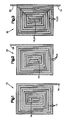
- two assembled coil pairs 30 have been formed as shown in Figure 3, and are "partially superimposed” with respect to each other.
- the resultant coil construction, indicated by the reference numeral 40 includes about 25% of the total turns overlapped at the center of the assembled coil pairs 30.
- FIG. 5A arrangements of two coil pairs 30 are shown as they might be used in practice to form part of a de-icer.
- the outermost portion of the de-icer will be distended as indicated at 42 so as to shatter, debond, and expel any ice that may have accumulated thereon.
- the coil pairs 30 are partially superimposed and an enhanced force will be generated in the region of the overlap where, presumably, the de-icing action will be enhanced.
- the enhanced distension of the de-icer is indicated by the reference numeral 44.
- the member 50 like the members 10, 20, is defined by a first, continuous, electrical conductor having a plurality of turns 52, a first end 54, and a second end 56. Unlike the members 10, 20, the second end 56 crosses a portion of the turns 52 and is disposed adjacent the first end 54 at a location outside the outermost turn 52.
- the first end 54 defines an electrical input to the member 50, while the second end 56 defines an electrical output from the member 50.
- the second end 56 is electrically isolated from the turns 52 that are crossed.
- the member 50 is formed from a single sheet of unalloyed copper or aluminum having a thickness of about 0.016 inch.
- the turns 52 have a width within the range of 0.070-0.125 inch.
- an assembled coil construction employing four sheet-like members 50 is indicated schematically by the reference numeral 60. Pairs of the members 50 are separated by dielectric layers 62 as well as the second end 56 of the members 50.
- the dielectric layers 62 preferably are formed of a material such as two layers of polyamide film, each having a thickness of about 0.003 inch.
- a suitable polyamide film is available from the E.I. Dupont deNemours & Company under the trademark KAPTON. Before use, the film should be surface-treated by acid-etching, plasma treating or the like to improve adhesion.
- the members 50 of the coil assembly 60 are shown displaced relative to each other for purposes of illustrating the directions of current flow therein.
- the uppermost member 50 is shown in solid lines, while the immediately adjacent lower member 50 is shown by dashed lines.
- the second end 56 of the uppermost sheet 50 is electrically connected to the first end 54 of the immediately adjacent lower member 50.
- the output of the lower member 50 is directed through the end 56 to the second end 56 of the lower member 50 of the adjacent coil pair.
- the lower coil pair members 50 are connected in the same manner as the upper coil pair members 50. However, because the electrical input is to the second end 56 of the lower member 50, current flow through the lower coil pairs is in a direction opposite to that of the upper coil pairs.
- the displacement of the coil force elements can be utilized in a de-icer to provide de-icing action. If the direction of current flow in the lower coil pair is reversed by electrically connecting the upper coil pair second end 56 to the first end 54 of the adjacent lower coil pair, current flow through the lower coil pair is in the same direction as that of the upper coil pair.
- the coil pairs thus may be used in an eddy current type of de-icer construction.
- FIGS 9A-9G a schematic view of planar coils according to the invention during their manufacture for an eddy current de-icer is illustrated. It will be assumed that the arrangement shown in Figures 9A-9G incorporates the members 10, 20, although the members 50 could be employed with equal facility.
- the member 10 is illustrated as it is manufactured initially in an etching operation.
- a sheet of unalloyed copper is attached to a backing sheet 70.
- the copper sheet is coated with a substance, such as a photo-resist material, that is impervious to an etching material such as sulfuric acid.
- the backing sheet 70 also is impervious to the acid.
- copper will be removed in those areas not protected by the photo-resist material.
- the sheet will take the appearance of the member 10 shown in Figure 1.
- the member 10 also could be formed in a stamping operation or a machining operation. If desired, the member 10 could be made from a continuous flat-braided conductor.
- the member 10 In order to process the member 10 further, it is necessary to remove it from the backing sheet 70. This result is accomplished by applying a layer of double-sided tape 72 to the exposed surface of the member 10.
- the tape 72 has a thickness of about 0.0045 inch.
- a suitable tape 72 can be obtained from Fasson Corporation under the trademark FASTAPE A.
- FASTAPE A Upon lifting the tape 72, the member 10 will be removed from the backing sheet 70.
- the edges of the tape 72 are trimmed to closely approximate the outer dimensions of the member 10.
- the exposed adhesive side of the tape 72 can be attached to a layer of dielectric material such as EAPTON film.
- the dielectric layer is indicated in Figure 9C by the reference numeral 74.
- the member 20 can be manufactured in an etching process and removed from its backing sheet 70 by means of a second layer of double-sided tape 72.
- the sandwiched coil construction 30 shown in Figure 9C will be obtained.
- the layer 74 extends laterally beyond the edges of the members 10, 20 and the tape 72 to form a border approximately 0.25 inch wide that prevents arcing between the edges of the members 10, 20.
- the coil assembly 30 of Figure 9C is illustrated as being sandwiched between layers 76 of a composite material such as fiberglass/epoxy.
- a suitable fiberglass/epoxy material can be obtained from Fiberite Corporation under the trademark MXB 7669/7781.
- the assembled components are placed in a mold where heat and pressure can be applied so as to conform the coil construction 30 to any desired contour.
- the embodiment illustrated in Figure 9D is flat, a curved contour should be employed if the coil assembly 30 is to be attached to the curved surface of a structural member.
- each layer 76 During the application of heat and pressure to the layers 76, it is expected that they will flow at least to a small extent so that gaps between adjacent turns 12, 22 will be filled.
- the initial thickness of each layer 76 is about 0.010 inch, and the final thickness of each layer 76 is about 0.005-0.006 inch.
- the edges of the layers 76 will be compressed toward each other to form a tapered configuration that assists in matching the contour of the structural member with which the coil assembly 30 is to be used.
- the coil assembly 30 of Figure 9D is shown as it might be attached to the external surface of a metal structural member 78.
- the innermost fiberglass/epoxy layer 76 is spaced from the structural member 78 by means of a release layer 80 that permits the coil assembly 30 to move away from and toward the structural member 78.
- the layer 80 is very thin (about 0.001 inch) and can be obtained from the Richmond Division of Dixico Incorporated under the trademark A5000.
- a surface ply 82 is positioned over the outermost surface of the exposed layer 76. The ply 82 is secured to the exposed layer 76 by an adhesive such as EA951 commercially available from the Hysol Corporation.
- the ply 82 is made of metal such as titanium, aluminum or stainless steel, it should be surface-treated for better adhesion. If the ply 82 is made of a thermoplastic material such as polyetherether ketone (PEEK), surface-treating also is necessary. If the ply 82 is made of another type of thermoplastic material, surface-treating may not be necessary. A metal ply 82 will have a thickness of about 0.005 inch while a non-metal ply 82 will have a thickness of about 0.015 inch. The ends of the layers 80, 82 are attached to the structural member 78 by bonding or any other suitable technique.
- PEEK polyetherether ketone
- an elastomeric support (not shown) would be provided at the ends of the layers 80, 82 in order to provide a smooth transition to the contour of the member 78 and to assist in securing the layers 80, 82 relative to the remainder of the de-icer structure. Regardless of how the layers 80, 82 are connected to the structure 78, it is necessary that at least the layer 82 be able to move away from, and toward, the structural member 78.
- FIG. 9F An additional variation is shown in Figure 9F.
- a release layer 84 is disposed intermediate the outermost encapsulating layer 76 and the surface ply 82. Accordingly, the surface ply 82 can move away from, and toward, the coil 30 upon energization thereof. Because the release layer 80 is used in the embodiment shown in Figure 9F, the coil 30 will move away from, and toward, the structural member 78 if the member 78 is made of metal. If the member 78 is made of a composite material, then the coil 30 will remain in contact with the outer surface of the member 78. In such a circumstance, it may be desirable to eliminate the release layer 80 and bond the innermost encapsulating layer 76 to the member 78 by means of an adhesive such as EA951. Regardless of the material from which the member 78 is made, it will be appreciated that the surface ply 82 always will be forcefully displaced away from, and toward, the member 78 so as to effect a de-icing action.
- a plot of force versus current is shown for coils constructed and arranged as shown in Figures 7 and 8 as a force element for an electro-repulsive type of de-icer.
- the tests that were conducted to generate the graph of Figure 10 were laboratory vice tests in which a transducer was disposed intermediate the adjacent coil pairs 50.
- the lower plot indicated by the reference numeral 86 shows that the force produced by the coil 60 is a direct function of the current supplied thereto.
- the uppermost curve indicated by the reference numeral 88 shows that disposing a paramagnetic target material (in this case 6061 aluminum, having a thickness of 0.060 inch) adjacent the outer surface of one of the members 50 produced an enhanced separation force.
- a paramagnetic target material in this case 6061 aluminum, having a thickness of 0.060 inch
- Figure 10 confirms that coil pairs operating on the so-called "electro-expulsion" principle such as that disclosed in the Electro-Repulsive Separation System Patent have excellent force-generating capabilities, but that such capabilities can be enhanced by the use of a metal target disposed in proximity with the coils. It is believed that this result is brought about by eddy currents that are induced in the target that create an electromagnetic field that interacts with the electromagnetic field generated by the coil 60. In effect, the magnetic target improves or shapes the magnetic field generated by the coil 60.
- plot 86 would be representative of the force produced by attaching the coil to a composite structural member 78
- plot 88 would be representative of the results produced by attaching the coil 60 to a metal structural member 78 or by using a metal surface ply 82 in conjunction with 0.060 inch thick metal targets adjacent the coils.
Abstract
Description
- U.S. Patent No. 4,875,644, Application Serial No. 07/258,279, filed October 14, 1988, entitled "Electro-Repulsive Separation System for De-icing," by Lowell J. Adams, et al., the disclosure of which is incorporated herein by reference (hereinafter referred to as the "Electro-Repulsive Separation System Patent").
- The invention relates to planar coils and, more particularly, to planar coils especially adapted for use in a force-producing device such as a de-icer.
- The accumulation of ice on aircraft wings and other structural members in flight is a danger that is well known. As used herein, the term "structural members" is intended to refer to any aircraft surface susceptible to icing during flight, including wings, stabilizers, engine inlets, rotors, and so forth. Attempts have been made since the earliest days of flight to overcome the problem of ice accumulation. While a variety of techniques have been proposed for removing ice from aircraft during flight, these techniques have had various drawbacks that have stimulated continued research activities.
- One approach that has been used extensively is so-called mechanical de-icing. In mechanical de-icing, the leading edges of structural members are distorted in some manner so as to crack ice that has accumulated thereon for dispersal into the airstream. A popular mechanical de-icing technique is the use of expandable tube-like structures that are periodically inflatable. Inflation of the structures results in their expansion or stretching by 40% or more. Such expansion typically occurs over approximately 2-6 seconds and results in a substantial change in the profile of the de-icer, thereby cracking accumulated ice. Unfortunately, expansion of the devices can negatively influence the airflow passing over the aircraft structure. Also, they are most effective when ice has accumulated to a substantial extent, approximately 0.25 inch or more, thereby limiting their effectiveness. Desirably, ice removal would be accomplished long before accumulations approximating 0.25 inch have been attained.
- A more recent mechanical de-icing technique utilizes internal "hammers" to distort the leading edges of structural members. Such an approach is exemplified by U.S. Patent No. 3,549,964 to Levin et al., wherein electrical pulses from a pulse generator are routed to a coil of a spark-gap pressure transducer disposed adjacent the inner wall of the structural member. The primary current in the coil induces a current in the wall of the structural member and the magnetic fields produced by the currents interact so as to deform the member.
- U.S. Patent Nos. 3,672,610 and 3,779,488 to Levin et al. and U.S. Patent No. 4,399,967 to Sandorff disclose aircraft de-icers that utilize energized induction coils to vibrate or torque the surface on which ice forms. Each of these devices employs electromagnetic coils or magneto-restrictive vibrators located on the side of the surface opposite to that on which ice accumulates. In U.S. Patent No. 3,809,341 to Levin et al., flat buses are arranged opposite one another, with one side of each bus being disposed adjacent an inner surface of an ice-collecting wall. An electric current is passed through each bus and the resulting interacting magnetic fields force the buses apart and deform the ice-collecting walls.
- A more recent approach is shown by U.S. Patent No. 4,690,353 to Haslim et al. In the '353 patent, one or more overlapped flexible ribbon conductors are imbedded in an elastomeric material that is affixed to the outer surface of a structural member. The conductors are fed large current pulses from a power storage unit. The resulting interacting magnetic fields produce an electro-expulsive force that distends the elastomeric member. The distension is almost instantaneous when a current pulse reaches the conductors, and is believed to be effective in removing thin layers of ice. Although the device disclosed in the '353 patent is believed to be an improvement over previous mechanical de-icing techniques, certain drawbacks remain. One of the drawbacks relates to the direction of current flow in adjacent electrically conductive members. It is believed that the current flow disclosed in the '353 patent produces inefficiencies that significantly restrict the effectiveness of the device.
- The Electro-Repulsive Separation System Patent discloses a device that is an improvement over that disclosed in the '353 patent. In the Electro-Repulsive Separation System Patent, the electrically conductive members are arranged with current flow in a common direction in a conductor layer such that a greater electro-expulsive force can be generated than with the serpentine configuration disclosed in the '353 patent. Also, the Electro-Repulsive Separation System Patent teaches the delivery of a current pulse of predetermined magnitude, shape and duration that provides more effective de-icing action.
- Despite the advances taught by the prior art, particularly the Electro-Repulsive Separation System Patent, there remains a need for a de-icer that provides effective de-icing action. A particular concern relates to the electrically conductive members that are used with the prior devices. It is desired to provide coils that are as thin as possible, while being relatively inexpensive and easy to manufacture. Desirably, any such coils would have a very high efficiency, that is, they would generate more force than prior electrically conductive members for a given current input. The coils also desirably would permit a small or large area of force production as desired for a de-icer construction.
- The present invention addresses the foregoing concerns and provides a new and improved planar coil construction especially adapted for use as part of a de-icer. The planar coil according to the invention includes a first sheet-like member defined by a first, continuous, electrical conductor having a plurality of turns and first and second ends. The first end of the first conductor defines an electrical input to the coil, and the second end of the first conductor defines an electrical output. The invention includes a second sheet-like member defined by a second, continuous, electrical conductor having a plurality of turns and first and second ends. The first end of the second conductor defines an electrical input, and the second end of the second conductor defines an electrical output from the coil. The second end of the first conductor and the first end of the second conductor are electrically connected. The first and second sheet-like members are disposed parallel to each other with the turns of the first and second conductors being positioned adjacent each other. The direction of current flow through the turns of the first conductor can be arranged to be substantially the same as that through the turns of the second conductor, or it can be arranged to be substantially opposite that through the turns of the second conductor. In addition, within a sheet-like member the adjacent conductors from the center out have current flow in the same direction, which is of particular importance for electro-repulsive force de-icers.
- In one embodiment of the invention, the turns are rectangular, while in other embodiments the turns are spiral-shaped, square, or any other desired geometry. The invention also includes a technique for separating the sheet-like members by a dielectric layer, as well as a means for encapsulating the sheet-like members. Additional sheet-like members can be provided, if desired, and connected to each other and to the first and second sheet-like members. When more than two members are used, if the direction of current flow in a given layer is opposite to the direction of current flow in adjacent layers, a strong repulsive force is created when a high current pulse is applied. If the direction of current flow in a given layer is in the same direction as in adjacent layers, it may be used for an eddy current de-icer. The invention also contemplates incorporating a ferromagnetic or paramagnetic material (hereinafter referred to as "magnetic material") on the outer and/or inner surface of the coil in order to improve or shape the magnetic field generated by the coil and increase the resultant force.
- Regardless of the embodiment of the invention that is utilized, the sheet-like members can be manufactured readily from metal foil or a flat-braided conductor. The coil according to the invention can be assembled readily, and it provides significant force-generating capabilities compared with prior coil constructions.
- The foregoing and other features and advantages of the present invention will become more apparent when viewed in light of the description of the best embodiment of the invention and the drawings that follow, which together form a part of the specification.
-
- Figure 1 is a plan view of a sheet-like member formed of a continuous electrical conductor that is usable with the present invention;
- Figure 2 is a view similar to Figure 1, showing another sheet-like member;
- Figure 3 is a view similar to Figure 1, showing the sheet-like members of Figures 1 and 2 completely superimposed;
- Figure 4 is a view similar to Figure 3, showing a first superimposed pair of sheet-like members partially superimposed with respect to a second pair of superimposed sheet-like members;
- Figures 5A and 5B are schematic cross-sectional views of planar coils according to the invention as they might be used in a de-icer;
- Figure 6 is a plan view of an alternative embodiment of the sheet-like member of Figure 1;
- Figure 7 is schematic, cross-sectional view of an assembled coil construction employing four superimposed sheet-like members;
- Figure 8 is a plan view of the coil construction of Figure 7, with the sheet-like members displaced relative to each other for clarity in illustrating the directions of current flow;
- Figures 9A-9F are cross-sectional views similar to Figure 7 showing how planar coils according to the invention can be assembled for use as a force-producing element as part of a de-icer;
- Figure 9G is a cross-sectional view of the coils of Figure 9A-9F taken along a plane indicated by
line 9G-9G in Figure 9C; and - Figure 10 is a plot of force versus current for coils as illustrated in Figures 7 and 8.
- The present invention provides a planar coil construction especially adapted for use as part of a de-icer that may be attached to the leading edges of structural members. De-icing is the removal of ice subsequent to its formation upon a leading edge. A leading edge is that portion of a structural member that functions to meet and break an airstream impinging upon the surface of the structural member. Examples of leading edges are the forward portions of wings, stabilizers, struts, nacelles, rotors and other housings and protrusions first impacted by an airstream.
- Although the planar coil construction of the present invention is described in the environment of a de-icer, it is to be understood that the invention can be used in other environments. For example, the invention could be used as a force-generating element in a vibratory conveyor, as a switching device, or in a variety of other applications. Accordingly, the invention as described and claimed herein shall not be limited solely to use in de-icer applications.
- Referring to Figure 1, a first, sheet-like member is indicated by the
reference numeral 10. Themember 10 is defined by a first, continuous, electrical conductor having a plurality ofturns 12, afirst end 14 and asecond end 16. Thefirst end 14 defines an electrical input to themember 10, while thesecond end 16 defines an electrical output from themember 10. Themember 10 is formed from a single sheet of unalloyed copper or aluminum having a thickness of about 0.016 inch. The turns 12 have a width within the range of 0.070-0.125 inch. - The
first end 14 is disposed at one corner of themember 10, while thesecond end 16 is disposed at the center. Although themember 10 is illustrated as being rectangular, it could be square, circular, or any other desired shape. - Referring to Figure 2, a second, sheet-like member is indicated by the
reference numeral 20. Themember 20 is defined by a second, continuous, electrical conductor having a plurality ofturns 22, afirst end 24, and asecond end 26. Thefirst end 24 defines an electrical input to themember 20, while thesecond end 26 defines an electrical output from themember 20. Themember 20 is formed from a single sheet of unalloyed copper or aluminum having a thickness of about 0.016 inch. The turns 22 have a width within the range of 0.070-0.125 inch. As with themember 10, themember 20 is rectangular, with one end disposed at a corner and the other end disposed at the center. - Referring to Figure 3, the
members reference numeral 30. In this arrangement, theturns 12 are disposed immediately adjacent comparable turns 22. The ends 16, 24 are joined as by soldering or welding to form an electrical connection. As will be appreciated from an examination of Figure 3, electrical current directed into thefirst end 14 will follow a path through theturns 12 that is in the same direction as the superimposed, adjacent turns 22. Thefirst member 10 typically has 12-1/8 turns, as does thesecond member 20. (An 8-1/8 turn member is shown for clarity of illustration). Accordingly, the superimposedmembers coil pair 30 having 24-1/2 turns. - Referring to Figure 4, two assembled coil pairs 30 have been formed as shown in Figure 3, and are "partially superimposed" with respect to each other. The resultant coil construction, indicated by the
reference numeral 40, includes about 25% of the total turns overlapped at the center of the assembled coil pairs 30. - Referring to Figure 5A, arrangements of two coil pairs 30 are shown as they might be used in practice to form part of a de-icer. As is explained in more detail in the Electro-Repulsive Separation System Patent, upon supplying a short-duration, shaped, high-current pulse to the coil pairs 30, the outermost portion of the de-icer will be distended as indicated at 42 so as to shatter, debond, and expel any ice that may have accumulated thereon. Referring to Figure 5B, the coil pairs 30 are partially superimposed and an enhanced force will be generated in the region of the overlap where, presumably, the de-icing action will be enhanced. The enhanced distension of the de-icer is indicated by the
reference numeral 44. - Referring to Figure 6, an alternative construction of a sheet-like member is indicated schematically by the
reference numeral 50. Themember 50, like themembers turns 52, afirst end 54, and asecond end 56. Unlike themembers second end 56 crosses a portion of theturns 52 and is disposed adjacent thefirst end 54 at a location outside theoutermost turn 52. Thefirst end 54 defines an electrical input to themember 50, while thesecond end 56 defines an electrical output from themember 50. Thesecond end 56 is electrically isolated from theturns 52 that are crossed. Themember 50 is formed from a single sheet of unalloyed copper or aluminum having a thickness of about 0.016 inch. The turns 52 have a width within the range of 0.070-0.125 inch. - Referring to Figure 7, an assembled coil construction employing four sheet-
like members 50 is indicated schematically by thereference numeral 60. Pairs of themembers 50 are separated bydielectric layers 62 as well as thesecond end 56 of themembers 50. The dielectric layers 62 preferably are formed of a material such as two layers of polyamide film, each having a thickness of about 0.003 inch. A suitable polyamide film is available from the E.I. Dupont deNemours & Company under the trademark KAPTON. Before use, the film should be surface-treated by acid-etching, plasma treating or the like to improve adhesion. - Referring to Figure 8, the
members 50 of thecoil assembly 60 are shown displaced relative to each other for purposes of illustrating the directions of current flow therein. Theuppermost member 50 is shown in solid lines, while the immediately adjacentlower member 50 is shown by dashed lines. As can be seen in Figure 8, thesecond end 56 of theuppermost sheet 50 is electrically connected to thefirst end 54 of the immediately adjacentlower member 50. The output of thelower member 50 is directed through theend 56 to thesecond end 56 of thelower member 50 of the adjacent coil pair. The lowercoil pair members 50 are connected in the same manner as the uppercoil pair members 50. However, because the electrical input is to thesecond end 56 of thelower member 50, current flow through the lower coil pairs is in a direction opposite to that of the upper coil pairs. As shown in Figure 8, current flow through the upper coil pairs is in a clockwise direction, while current flow through the lower coil pairs is in a counterclockwise direction. Due to the opposing directions of current flow in the upper coil pair and lower coil pair conductors, and because the coil pairs are separated by theKAPTON film 62, upon supplying a short-duration, high-current pulse to thecoil 60, the respective upper and lower coil pairs will be forcefully displaced away from each other. This would constitute a force element for an electro-repulsive type of de-icer. - As in the de-icer schematically indicated in Figure 5A, the displacement of the coil force elements can be utilized in a de-icer to provide de-icing action. If the direction of current flow in the lower coil pair is reversed by electrically connecting the upper coil pair
second end 56 to thefirst end 54 of the adjacent lower coil pair, current flow through the lower coil pair is in the same direction as that of the upper coil pair. The coil pairs thus may be used in an eddy current type of de-icer construction. - Referring to Figures 9A-9G, a schematic view of planar coils according to the invention during their manufacture for an eddy current de-icer is illustrated. It will be assumed that the arrangement shown in Figures 9A-9G incorporates the
members members 50 could be employed with equal facility. - In Figure 9A, the
member 10 is illustrated as it is manufactured initially in an etching operation. In such an operation, a sheet of unalloyed copper is attached to abacking sheet 70. The copper sheet is coated with a substance, such as a photo-resist material, that is impervious to an etching material such as sulfuric acid. Thebacking sheet 70 also is impervious to the acid. Upon applying the acid to the surface of the copper sheet, copper will be removed in those areas not protected by the photo-resist material. After the copper in the unprotected areas has been removed, the sheet will take the appearance of themember 10 shown in Figure 1. Themember 10 also could be formed in a stamping operation or a machining operation. If desired, themember 10 could be made from a continuous flat-braided conductor. - In order to process the
member 10 further, it is necessary to remove it from thebacking sheet 70. This result is accomplished by applying a layer of double-sided tape 72 to the exposed surface of themember 10. Thetape 72 has a thickness of about 0.0045 inch. Asuitable tape 72 can be obtained from Fasson Corporation under the trademark FASTAPE A. Upon lifting thetape 72, themember 10 will be removed from thebacking sheet 70. The edges of thetape 72 are trimmed to closely approximate the outer dimensions of themember 10. Thereafter, the exposed adhesive side of thetape 72 can be attached to a layer of dielectric material such as EAPTON film. The dielectric layer is indicated in Figure 9C by thereference numeral 74. Similarly, themember 20 can be manufactured in an etching process and removed from itsbacking sheet 70 by means of a second layer of double-sided tape 72. Upon attaching the exposed surface of the second double-sided tape 72 to the exposed surface of thedielectric layer 74, the sandwichedcoil construction 30 shown in Figure 9C will be obtained. As shown in Figure 9G, thelayer 74 extends laterally beyond the edges of themembers tape 72 to form a border approximately 0.25 inch wide that prevents arcing between the edges of themembers - In order to protect the
members members coil assembly 30 of Figure 9C is illustrated as being sandwiched betweenlayers 76 of a composite material such as fiberglass/epoxy. A suitable fiberglass/epoxy material can be obtained from Fiberite Corporation under the trademark MXB 7669/7781. After thelayers 76 are assembled as illustrated in Figure 9D, the assembled components are placed in a mold where heat and pressure can be applied so as to conform thecoil construction 30 to any desired contour. Although the embodiment illustrated in Figure 9D is flat, a curved contour should be employed if thecoil assembly 30 is to be attached to the curved surface of a structural member. During the application of heat and pressure to thelayers 76, it is expected that they will flow at least to a small extent so that gaps betweenadjacent turns layer 76 is about 0.010 inch, and the final thickness of eachlayer 76 is about 0.005-0.006 inch. Also, the edges of thelayers 76 will be compressed toward each other to form a tapered configuration that assists in matching the contour of the structural member with which thecoil assembly 30 is to be used. - Referring to Figure 9E, the
coil assembly 30 of Figure 9D is shown as it might be attached to the external surface of a metalstructural member 78. The innermost fiberglass/epoxy layer 76 is spaced from thestructural member 78 by means of arelease layer 80 that permits thecoil assembly 30 to move away from and toward thestructural member 78. Thelayer 80 is very thin (about 0.001 inch) and can be obtained from the Richmond Division of Dixico Incorporated under the trademark A5000. A surface ply 82 is positioned over the outermost surface of the exposedlayer 76. Theply 82 is secured to the exposedlayer 76 by an adhesive such as EA951 commercially available from the Hysol Corporation. If theply 82 is made of metal such as titanium, aluminum or stainless steel, it should be surface-treated for better adhesion. If theply 82 is made of a thermoplastic material such as polyetherether ketone (PEEK), surface-treating also is necessary. If theply 82 is made of another type of thermoplastic material, surface-treating may not be necessary. A metal ply 82 will have a thickness of about 0.005 inch while anon-metal ply 82 will have a thickness of about 0.015 inch. The ends of thelayers structural member 78 by bonding or any other suitable technique. Typically, an elastomeric support (not shown) would be provided at the ends of thelayers member 78 and to assist in securing thelayers layers structure 78, it is necessary that at least thelayer 82 be able to move away from, and toward, thestructural member 78. - In operation, upon supplying a short-duration, shaped, high-current pulse to the
coil 30, an electromagnetic field will be generated that will induce eddy currents in thestructural member 78 and to a lesser extent in thethin surface ply 82. The eddy currents then will generate electromagnetic fields which will tend to repel the electromagnetic field of thecoil 30. In turn, thecoil 30, with the surface ply 82 attached, will be forcefully displaced away from thestructural member 78. Upon collapse of the magnetic fields, thecoil 30 and the surface ply 82 will be forcefully retracted against thestructural member 78 to that position shown in Figure 9E. If thestructural member 78 is made of a composite material such as graphite/epoxy instead of metal, a metal target (a so-called "doubler") should be disposed on the outside or inside of themember 78. - An additional variation is shown in Figure 9F. In Figure 9F, a
release layer 84 is disposed intermediate theoutermost encapsulating layer 76 and thesurface ply 82. Accordingly, the surface ply 82 can move away from, and toward, thecoil 30 upon energization thereof. Because therelease layer 80 is used in the embodiment shown in Figure 9F, thecoil 30 will move away from, and toward, thestructural member 78 if themember 78 is made of metal. If themember 78 is made of a composite material, then thecoil 30 will remain in contact with the outer surface of themember 78. In such a circumstance, it may be desirable to eliminate therelease layer 80 and bond theinnermost encapsulating layer 76 to themember 78 by means of an adhesive such as EA951. Regardless of the material from which themember 78 is made, it will be appreciated that the surface ply 82 always will be forcefully displaced away from, and toward, themember 78 so as to effect a de-icing action. - Referring to Figure 10, a plot of force versus current is shown for coils constructed and arranged as shown in Figures 7 and 8 as a force element for an electro-repulsive type of de-icer. The tests that were conducted to generate the graph of Figure 10 were laboratory vice tests in which a transducer was disposed intermediate the adjacent coil pairs 50. The lower plot indicated by the
reference numeral 86 shows that the force produced by thecoil 60 is a direct function of the current supplied thereto. The uppermost curve indicated by thereference numeral 88 shows that disposing a paramagnetic target material (in this case 6061 aluminum, having a thickness of 0.060 inch) adjacent the outer surface of one of themembers 50 produced an enhanced separation force. The difference ranges from approximately 19% at lower current levels to 9% at higher current levels. Figure 10 confirms that coil pairs operating on the so-called "electro-expulsion" principle such as that disclosed in the Electro-Repulsive Separation System Patent have excellent force-generating capabilities, but that such capabilities can be enhanced by the use of a metal target disposed in proximity with the coils. It is believed that this result is brought about by eddy currents that are induced in the target that create an electromagnetic field that interacts with the electromagnetic field generated by thecoil 60. In effect, the magnetic target improves or shapes the magnetic field generated by thecoil 60. It is believed that theplot 86 would be representative of the force produced by attaching the coil to a compositestructural member 78, while theplot 88 would be representative of the results produced by attaching thecoil 60 to a metalstructural member 78 or by using a metal surface ply 82 in conjunction with 0.060 inch thick metal targets adjacent the coils. - Although the invention has been described in its preferred form with a certain degree of particularity, it will be understood that the present disclosure of the preferred embodiment has been made only by way of example, and that various changes may be resorted to without departing from the true spirit and scope of the invention as hereinafter claimed. It is intended that the patent shall cover, by suitable expression in the appended claims, whatever features of patentable novelty exist in the invention disclosed.
Claims (39)
a first, sheet-like member defined by a first, continuous, electrical conductor having a plurality of turns and first and second ends, the first end of the first conductor defining an electrical input and the second end of the first conductor defining an electrical output;
a second, sheet-like member defined by a second, continuous, electrical conductor having a plurality of turns and first and second ends, the first end of the second conductor defining an electrical input, and the second end of the second conductor defining an electrical output;
an electrical connection between the second end of the first conductor and the first end of the second conductor; and
the first and second sheet-like members being disposed parallel to each other with selected turns of the first electrical conductor being positioned adjacent to selected turns of the second electrical conductor such that the direction of current flow through the turns of the first conductor is substantially in the same direction as the current flow through the turns of the second conductor.
a sheet-like layer of dielectric material disposed between the opposing layers of two-sided tape; and
encapsulation means for encapsulating the assembled sheet-like members, the means for encapsulating serving as a dielectric and protecting the sheet-like members.
a first, sheet-like member defined by a first, continuous, electrical conductor having a plurality of turns and first and second ends, the first end of the first conductor defining an electrical input and the second end of the first conductor defining an electrical output;
a second, sheet-like member defined by a second, continuous, electrical conductor having a plurality of turns and first and second ends, the first end of the second conductor defining an electrical input, and the second end of the second conductor defining an electrical output;
an electrical connection between the second end of the first conductor and the first end of the second conductor; and
the first and second sheet-like members being disposed parallel to each other with selected turns of the first electrical conductor being positioned adjacent to selected turns of the second electrical conductor such that the direction of current flow through the turns of the first conductor is substantially in the opposite direction as the current flow through the turns of the second conductor.
separable sheet-like layers of dielectric material disposed between the opposing layers of two-sided tape; and
encapsulation means for encapsulating the assembled sheet-like members, the means for encapsulating serving as a dielectric and protecting the sheet-like members.
providing a first, sheet-like member defined by a first, continuous electrical conductor having a plurality of turns and first and second ends, the first end of the first conductor defining an electrical input and the second end of the first conductor defining an electrical output;
providing a second, sheet-like member defined by a first, continuous electrical conductor having a plurality of turns and first and second ends, the first end of the first conductor defining an electrical input and the second end of the first conductor defining an electrical output;
establishing an electrical connection between the second end of the first conductor and the first end of the second conductor; and
disposing the first and second sheet-like members parallel to each other with selected turns of the first electrical conductor being positioned adjacent to selected turns of the second electrical conductor such that the direction of current flow through the turns of the first conductor is substantially in the same direction as the current flow through the turns of the second conductor.
applying a layer of two-sided tape to a selected side of each of the first and second sheet-like members; and attaching the exposed surfaces of the two-sided tape layers to the opposite sides of a layer of dielectric material.
providing a first, sheet-like member defined by a first, continuous electrical conductor having a plurality of turns and first and second ends, the first end of the first conductor defining an electrical input and the second end of the first conductor defining an electrical output;
providing a second, sheet-like member defined by a first, continuous electrical conductor having a plurality of turns and first and second ends, the first end of the first conductor defining an electrical input and the second end of the first conductor defining an electrical output;
establishing an electrical connection between the second end of the first conductor and the first end of the second conductor; and
disposing the first and second sheet-like members parallel to each other with selected turns of the first electrical conductor being positioned adjacent to selected turns of the second electrical conductor such that the direction of current flow through the turns of the first conductor is substantially in the opposite direction as the current flow through the turns of the second conductor.
applying a layer of two-sided tape to a selected side of each of the first and second sheet-like members; and
attaching the exposed surfaces of the two-sided tape layers to the opposite sides of layers of dielectric material.
Applications Claiming Priority (2)
| Application Number | Priority Date | Filing Date | Title |
|---|---|---|---|
| US07/437,489 US5152480A (en) | 1989-11-15 | 1989-11-15 | Planar coil construction |
| US437489 | 1989-11-15 |
Publications (3)
| Publication Number | Publication Date |
|---|---|
| EP0428142A2 true EP0428142A2 (en) | 1991-05-22 |
| EP0428142A3 EP0428142A3 (en) | 1992-12-23 |
| EP0428142B1 EP0428142B1 (en) | 1995-08-09 |
Family
ID=23736670
Family Applications (1)
| Application Number | Title | Priority Date | Filing Date |
|---|---|---|---|
| EP90121729A Expired - Lifetime EP0428142B1 (en) | 1989-11-15 | 1990-11-13 | Planar coil construction |
Country Status (9)
| Country | Link |
|---|---|
| US (1) | US5152480A (en) |
| EP (1) | EP0428142B1 (en) |
| JP (1) | JPH03208306A (en) |
| CN (1) | CN1037473C (en) |
| BR (1) | BR9005795A (en) |
| CA (1) | CA2029687C (en) |
| DE (1) | DE69021509T2 (en) |
| ES (1) | ES2078284T3 (en) |
| IL (1) | IL96350A0 (en) |
Cited By (5)
| Publication number | Priority date | Publication date | Assignee | Title |
|---|---|---|---|---|
| EP0433763A2 (en) * | 1989-12-22 | 1991-06-26 | The B.F. Goodrich Company | Attachable electro-impulse de-icer |
| DE4317545A1 (en) * | 1992-05-27 | 1993-12-02 | Fuji Electric Co Ltd | Thin film transformer |
| EP0713229A1 (en) * | 1994-11-17 | 1996-05-22 | International Business Machines Corporation | Planar transformer and method of manufacture |
| FR2906786A1 (en) * | 2006-10-09 | 2008-04-11 | Eurocopter France | Aircraft i.e. rotocraft, wall outer face defrosting device for helicopter manufacture field, has thin inductors generating heating of plate when inductors are supplied by current source without heating composite structure |
| ITMI20111036A1 (en) * | 2011-06-09 | 2012-12-10 | F & B Internat S R L | MAGNETIC FIELD INDUCTOR |
Families Citing this family (35)
| Publication number | Priority date | Publication date | Assignee | Title |
|---|---|---|---|---|
| US5346160A (en) * | 1992-06-30 | 1994-09-13 | The B. F. Goodrich Company | Electro-expulsive deicing system having fail safe conductive bridge means |
| US5326051A (en) * | 1992-06-30 | 1994-07-05 | The B. F. Goodrich Company | Electro-expulsive deicing system having circuit board expulsive members |
| JPH06310324A (en) * | 1993-04-21 | 1994-11-04 | Nippon Mektron Ltd | Plane coil |
| CN1113475A (en) * | 1993-10-01 | 1995-12-20 | B·F·谷德里奇公司 | Polyurethane deicer |
| US5429327A (en) * | 1993-10-22 | 1995-07-04 | The B.F. Goodrich Company | Electro-impulse de-icer |
| US5463291A (en) * | 1993-12-23 | 1995-10-31 | Carroll; Lewis | Cyclotron and associated magnet coil and coil fabricating process |
| US5553815A (en) * | 1994-04-07 | 1996-09-10 | The B. F. Goodrich Company | De-icer adapted for installment on the inner surface of a structural member |
| US5531405A (en) * | 1994-08-23 | 1996-07-02 | Dynamics Controls Corporation | Method of building an expulsive blanket using composite materials and stitched attachment |
| US6352601B1 (en) | 1994-12-27 | 2002-03-05 | The B. F. Goodrich Company | Self-adhering ice protector |
| US5782435A (en) * | 1995-05-24 | 1998-07-21 | Cox & Company, Inc. | Electro-magnetic expulsion de-icing system |
| US5657952A (en) * | 1995-07-31 | 1997-08-19 | Dynamic Controls Hs, Inc. | Electro-expulsive de-icing apparatus and method of use |
| CA2204486A1 (en) | 1996-05-06 | 1997-11-06 | Richard Lawrence Rauckhorst Iii | Pneumatic deicing system with protection for super cooled large droplet ice |
| FR2756253B1 (en) * | 1996-11-27 | 1999-01-29 | Eurocopter France | RESISTIVE ELEMENTS FOR HEATING AN AERODYNAMIC PROFILE, AND DEVICE FOR HEATING AN AERODYNAMIC PROFILE INCORPORATING SUCH ELEMENTS |
| CA2227526A1 (en) * | 1997-01-21 | 1998-07-21 | Michael J. Giamati | Hybrid deicer with element sequence control |
| EP0872417A1 (en) | 1997-04-16 | 1998-10-21 | The B.F. Goodrich Company | Hybrid deicer |
| US6283411B1 (en) | 1998-01-21 | 2001-09-04 | The B.F. Goodrich Company | Hybrid deicer with element sequence control |
| US6707210B2 (en) * | 2001-03-30 | 2004-03-16 | Hsieh Hsin-Mao | Dual wire stator coil for a radiator fan |
| DE10209415B4 (en) * | 2002-03-05 | 2005-12-01 | Siemens Ag | Device for non-contact radio frequency transmission |
| DE10209416B4 (en) * | 2002-03-05 | 2006-10-19 | Siemens Ag | Device for non-contact radio frequency transmission |
| US6570819B1 (en) | 2002-03-08 | 2003-05-27 | The United States Of America As Represented By The Secretary Of The Navy | Low frequency acoustic projector |
| GB0307729D0 (en) | 2003-04-03 | 2003-05-07 | Tesla Engineering Ltd | Manufacture of shim windings |
| US7124983B2 (en) * | 2004-08-20 | 2006-10-24 | Honeywell International, Inc. | Hybrid electrical ice protection system and method including an energy saving mode |
| US7548489B1 (en) | 2006-07-05 | 2009-06-16 | The United States Of America As Represented By The Secretary Of The Navy | Method for designing a resonant acoustic projector |
| US7443764B1 (en) | 2006-07-05 | 2008-10-28 | The United States Of America As Represented By The Secretary Of The Navy | Resonant acoustic projector |
| JP2009107515A (en) * | 2007-10-31 | 2009-05-21 | Shin Meiwa Ind Co Ltd | Manufacturing method for composite material structure for aircraft and structure |
| FR2935357B1 (en) * | 2008-09-03 | 2010-08-27 | Aircelle Sa | METHOD FOR MANUFACTURING A NACELLE ELEMENT |
| FR2943038B1 (en) * | 2009-03-13 | 2012-07-27 | Aircelle Sa | DEFROSTING DEVICE, IN PARTICULAR FOR AN AIRCRAFT NACELLE |
| US9108735B2 (en) * | 2009-05-13 | 2015-08-18 | Tmc Aerospace, Inc. | Electro-expulsive de-icing system for aircraft and other applications |
| WO2012044213A1 (en) * | 2010-09-28 | 2012-04-05 | Saab Ab | Method and arrangement for de-icing a structural element |
| JP5355618B2 (en) * | 2011-03-10 | 2013-11-27 | 三星ディスプレイ株式會社 | Flexible display device and manufacturing method thereof |
| WO2014138237A1 (en) * | 2013-03-05 | 2014-09-12 | Parviz Acquisitons Llc | Single surface electro-mechanical actuator assembly |
| CA3014831A1 (en) | 2016-02-16 | 2017-08-24 | Peter LENKEY | Deicing apparatuses |
| US10189572B2 (en) * | 2016-05-02 | 2019-01-29 | The Boeing Company | Systems and methods for preventing ice formation on portions of an aircraft |
| GB2574184B (en) * | 2018-03-29 | 2020-12-02 | Gkn Aerospace Services Ltd | Ice removal system |
| US20230312111A1 (en) * | 2022-04-05 | 2023-10-05 | Goodrich Corporation | Systems and methods for an ice runback control zone in an electrothermal ice protection system |
Citations (3)
| Publication number | Priority date | Publication date | Assignee | Title |
|---|---|---|---|---|
| JPS56167313A (en) * | 1980-05-27 | 1981-12-23 | Ono Sokki Co Ltd | Formation of inductance element |
| JPS5759309A (en) * | 1980-09-29 | 1982-04-09 | Matsushita Electric Works Ltd | Coil |
| EP0310396A1 (en) * | 1987-09-29 | 1989-04-05 | Kabushiki Kaisha Toshiba | Planar inductor |
Family Cites Families (11)
| Publication number | Priority date | Publication date | Assignee | Title |
|---|---|---|---|---|
| GB505433A (en) * | 1937-11-05 | 1939-05-05 | Rudolf Goldschmidt | Improvements in and relating to de-icing equipment, for example for aircraft |
| US3549964A (en) * | 1968-03-01 | 1970-12-22 | Levin Igor A | Device for deicing surfaces of thin-walled structures |
| DE1921639A1 (en) * | 1968-06-24 | 1970-05-06 | Levin Igor Anatoljevic | Electrical system of a deicer for the surface of thin-walled structures |
| US3809341A (en) * | 1972-11-14 | 1974-05-07 | I Levin | Device for removing ice from surfaces of thin-walled structures |
| US4399967A (en) * | 1980-12-09 | 1983-08-23 | Lockheed Corporation | Staggered coil and nose-torquer electromagnetic pulse deicing systems |
| US4458865A (en) * | 1980-12-09 | 1984-07-10 | Lockheed Corporation | Nose-torquer electro-impulse deicing systems |
| US4501398A (en) * | 1980-12-09 | 1985-02-26 | Lockheed Corporation | Beam balancer electro-impulse deicing systems |
| US4545553A (en) * | 1983-02-25 | 1985-10-08 | The United States Of America As Represented By The United States National Aeronautics And Space Administration | Piezoelectric deicing device |
| US4678144A (en) * | 1984-10-26 | 1987-07-07 | Simmonds Precision | Electro-impulse de-icing system for aircraft |
| US4690353A (en) * | 1985-05-31 | 1987-09-01 | The United States Of America As Represented By The Administrator Of The National Aeronautics And Space Administration | Electro-expulsive separation system |
| US4875644A (en) * | 1988-10-14 | 1989-10-24 | The B. F. Goodrich Company | Electro-repulsive separation system for deicing |
-
1989
- 1989-11-15 US US07/437,489 patent/US5152480A/en not_active Expired - Fee Related
-
1990
- 1990-11-09 CA CA002029687A patent/CA2029687C/en not_active Expired - Fee Related
- 1990-11-13 EP EP90121729A patent/EP0428142B1/en not_active Expired - Lifetime
- 1990-11-13 DE DE69021509T patent/DE69021509T2/en not_active Expired - Fee Related
- 1990-11-13 ES ES90121729T patent/ES2078284T3/en not_active Expired - Lifetime
- 1990-11-14 BR BR909005795A patent/BR9005795A/en not_active Application Discontinuation
- 1990-11-14 IL IL96350A patent/IL96350A0/en not_active IP Right Cessation
- 1990-11-15 JP JP2307371A patent/JPH03208306A/en active Pending
- 1990-11-15 CN CN90109172A patent/CN1037473C/en not_active Expired - Fee Related
Patent Citations (3)
| Publication number | Priority date | Publication date | Assignee | Title |
|---|---|---|---|---|
| JPS56167313A (en) * | 1980-05-27 | 1981-12-23 | Ono Sokki Co Ltd | Formation of inductance element |
| JPS5759309A (en) * | 1980-09-29 | 1982-04-09 | Matsushita Electric Works Ltd | Coil |
| EP0310396A1 (en) * | 1987-09-29 | 1989-04-05 | Kabushiki Kaisha Toshiba | Planar inductor |
Non-Patent Citations (2)
| Title |
|---|
| PATENT ABSTRACTS OF JAPAN vol. 6, no. 132 (E-119)(1010) 17 July 1982 & JP-A-57 59 309 ( MATSUSHITA DENKO ) 9 April 1982 * |
| PATENT ABSTRACTS OF JAPAN vol. 6, no. 55 (E-101)(933) 10 April 1982 & JP-A-56 167 313 ( ONO SOTSUKI ) 23 December 1981 * |
Cited By (10)
| Publication number | Priority date | Publication date | Assignee | Title |
|---|---|---|---|---|
| EP0433763A2 (en) * | 1989-12-22 | 1991-06-26 | The B.F. Goodrich Company | Attachable electro-impulse de-icer |
| EP0433763B1 (en) * | 1989-12-22 | 1998-11-18 | The BFGoodrich Company | Attachable electro-impulse de-icer |
| DE4317545A1 (en) * | 1992-05-27 | 1993-12-02 | Fuji Electric Co Ltd | Thin film transformer |
| EP0713229A1 (en) * | 1994-11-17 | 1996-05-22 | International Business Machines Corporation | Planar transformer and method of manufacture |
| US5754088A (en) * | 1994-11-17 | 1998-05-19 | International Business Machines Corporation | Planar transformer and method of manufacture |
| FR2906786A1 (en) * | 2006-10-09 | 2008-04-11 | Eurocopter France | Aircraft i.e. rotocraft, wall outer face defrosting device for helicopter manufacture field, has thin inductors generating heating of plate when inductors are supplied by current source without heating composite structure |
| EP1911673A1 (en) * | 2006-10-09 | 2008-04-16 | Eurocopter | Method and device for de-icing the wall of an aircraft |
| RU2466064C2 (en) * | 2006-10-09 | 2012-11-10 | Еврокоптер | Method and device to prevent aircraft skin icing |
| ITMI20111036A1 (en) * | 2011-06-09 | 2012-12-10 | F & B Internat S R L | MAGNETIC FIELD INDUCTOR |
| EP2533255A1 (en) * | 2011-06-09 | 2012-12-12 | F&B International S.r.l. | Magnetic field inductor |
Also Published As
| Publication number | Publication date |
|---|---|
| CN1051819A (en) | 1991-05-29 |
| IL96350A0 (en) | 1991-08-16 |
| EP0428142A3 (en) | 1992-12-23 |
| DE69021509T2 (en) | 1996-03-28 |
| DE69021509D1 (en) | 1995-09-14 |
| CN1037473C (en) | 1998-02-18 |
| JPH03208306A (en) | 1991-09-11 |
| CA2029687A1 (en) | 1991-05-16 |
| ES2078284T3 (en) | 1995-12-16 |
| EP0428142B1 (en) | 1995-08-09 |
| CA2029687C (en) | 2001-04-17 |
| US5152480A (en) | 1992-10-06 |
| BR9005795A (en) | 1991-09-24 |
Similar Documents
| Publication | Publication Date | Title |
|---|---|---|
| US5142767A (en) | Method of manufacturing a planar coil construction | |
| US5152480A (en) | Planar coil construction | |
| USRE38024E1 (en) | Attachable electro-impulse de-icer | |
| US4690353A (en) | Electro-expulsive separation system | |
| US5143325A (en) | Electromagnetic repulsion system for removing contaminants such as ice from the surfaces of aircraft and other objects | |
| US4875644A (en) | Electro-repulsive separation system for deicing | |
| US5429327A (en) | Electro-impulse de-icer | |
| JP4773659B2 (en) | Piezoelectric macro-fiber composite actuator and manufacturing method thereof | |
| EP2330034B1 (en) | Ice protection heater for an aircraft component | |
| EP0604751B1 (en) | Compressible nose dynamic deicer | |
| US6102333A (en) | Electro-magnetic expulsion de-icing system | |
| US5584450A (en) | Metal clad electro-expulsive deicer with segmented elements | |
| EP0422746B1 (en) | Improved expulsive separation apparatus | |
| CA2379351A1 (en) | Zoned aircraft de-icing system and method | |
| WO2019186206A1 (en) | Ice removal system | |
| US6126061A (en) | Element made of composite material including electrical continuity through the element | |
| US5326051A (en) | Electro-expulsive deicing system having circuit board expulsive members | |
| EP0067506A1 (en) | Aircraft de-icer | |
| EP3297394B1 (en) | Nano alumina fabric protection ply for de-icers | |
| Haslim et al. | Electro-expulsive separation system | |
| EP2724946A2 (en) | Carbon fiber spacecraft panel with integral metallic foil power return | |
| CN116713607A (en) | Laser cutting processing method for metal electrothermal grid | |
| JPH04230498A (en) | Electric exclusion type separator |
Legal Events
| Date | Code | Title | Description |
|---|---|---|---|
| PUAI | Public reference made under article 153(3) epc to a published international application that has entered the european phase |
Free format text: ORIGINAL CODE: 0009012 |
|
| 17P | Request for examination filed |
Effective date: 19901206 |
|
| AK | Designated contracting states |
Kind code of ref document: A2 Designated state(s): CH DE ES FR GB IT LI NL |
|
| PUAL | Search report despatched |
Free format text: ORIGINAL CODE: 0009013 |
|
| AK | Designated contracting states |
Kind code of ref document: A3 Designated state(s): CH DE ES FR GB IT LI NL |
|
| 17Q | First examination report despatched |
Effective date: 19940222 |
|
| GRAA | (expected) grant |
Free format text: ORIGINAL CODE: 0009210 |
|
| AK | Designated contracting states |
Kind code of ref document: B1 Designated state(s): CH DE ES FR GB IT LI NL |
|
| REF | Corresponds to: |
Ref document number: 69021509 Country of ref document: DE Date of ref document: 19950914 |
|
| ET | Fr: translation filed | ||
| ITF | It: translation for a ep patent filed |
Owner name: ING. C. GREGORJ S.P.A. |
|
| PGFP | Annual fee paid to national office [announced via postgrant information from national office to epo] |
Ref country code: ES Payment date: 19951116 Year of fee payment: 6 |
|
| PGFP | Annual fee paid to national office [announced via postgrant information from national office to epo] |
Ref country code: NL Payment date: 19951130 Year of fee payment: 6 Ref country code: CH Payment date: 19951130 Year of fee payment: 6 |
|
| REG | Reference to a national code |
Ref country code: ES Ref legal event code: FG2A Ref document number: 2078284 Country of ref document: ES Kind code of ref document: T3 |
|
| PLBE | No opposition filed within time limit |
Free format text: ORIGINAL CODE: 0009261 |
|
| STAA | Information on the status of an ep patent application or granted ep patent |
Free format text: STATUS: NO OPPOSITION FILED WITHIN TIME LIMIT |
|
| 26N | No opposition filed | ||
| PG25 | Lapsed in a contracting state [announced via postgrant information from national office to epo] |
Ref country code: ES Free format text: LAPSE BECAUSE OF NON-PAYMENT OF DUE FEES Effective date: 19961114 |
|
| PG25 | Lapsed in a contracting state [announced via postgrant information from national office to epo] |
Ref country code: LI Free format text: LAPSE BECAUSE OF FAILURE TO SUBMIT A TRANSLATION OF THE DESCRIPTION OR TO PAY THE FEE WITHIN THE PRESCRIBED TIME-LIMIT Effective date: 19961130 Ref country code: CH Free format text: LAPSE BECAUSE OF FAILURE TO SUBMIT A TRANSLATION OF THE DESCRIPTION OR TO PAY THE FEE WITHIN THE PRESCRIBED TIME-LIMIT Effective date: 19961130 |
|
| PG25 | Lapsed in a contracting state [announced via postgrant information from national office to epo] |
Ref country code: NL Effective date: 19970601 |
|
| NLV4 | Nl: lapsed or anulled due to non-payment of the annual fee |
Effective date: 19970601 |
|
| PGFP | Annual fee paid to national office [announced via postgrant information from national office to epo] |
Ref country code: FR Payment date: 20001018 Year of fee payment: 11 |
|
| PGFP | Annual fee paid to national office [announced via postgrant information from national office to epo] |
Ref country code: DE Payment date: 20001019 Year of fee payment: 11 |
|
| PGFP | Annual fee paid to national office [announced via postgrant information from national office to epo] |
Ref country code: GB Payment date: 20001020 Year of fee payment: 11 |
|
| PG25 | Lapsed in a contracting state [announced via postgrant information from national office to epo] |
Ref country code: GB Free format text: LAPSE BECAUSE OF NON-PAYMENT OF DUE FEES Effective date: 20011113 |
|
| REG | Reference to a national code |
Ref country code: GB Ref legal event code: IF02 |
|
| PG25 | Lapsed in a contracting state [announced via postgrant information from national office to epo] |
Ref country code: DE Free format text: LAPSE BECAUSE OF NON-PAYMENT OF DUE FEES Effective date: 20020702 |
|
| PG25 | Lapsed in a contracting state [announced via postgrant information from national office to epo] |
Ref country code: FR Free format text: LAPSE BECAUSE OF NON-PAYMENT OF DUE FEES Effective date: 20020730 |
|
| REG | Reference to a national code |
Ref country code: FR Ref legal event code: ST |
|
| REG | Reference to a national code |
Ref country code: FR Ref legal event code: ST |
|
| REG | Reference to a national code |
Ref country code: ES Ref legal event code: FD2A Effective date: 19971213 |
|
| PG25 | Lapsed in a contracting state [announced via postgrant information from national office to epo] |
Ref country code: IT Free format text: LAPSE BECAUSE OF NON-PAYMENT OF DUE FEES Effective date: 20051113 |