EP0428082A2 - A 3-dimensional configuration recognition system - Google Patents
A 3-dimensional configuration recognition system Download PDFInfo
- Publication number
- EP0428082A2 EP0428082A2 EP19900121493 EP90121493A EP0428082A2 EP 0428082 A2 EP0428082 A2 EP 0428082A2 EP 19900121493 EP19900121493 EP 19900121493 EP 90121493 A EP90121493 A EP 90121493A EP 0428082 A2 EP0428082 A2 EP 0428082A2
- Authority
- EP
- European Patent Office
- Prior art keywords
- checker pattern
- dimensional
- point
- recognition system
- cross points
- Prior art date
- Legal status (The legal status is an assumption and is not a legal conclusion. Google has not performed a legal analysis and makes no representation as to the accuracy of the status listed.)
- Withdrawn
Links
Images

Classifications
-
- G—PHYSICS
- G06—COMPUTING; CALCULATING OR COUNTING
- G06T—IMAGE DATA PROCESSING OR GENERATION, IN GENERAL
- G06T7/00—Image analysis
- G06T7/50—Depth or shape recovery
- G06T7/521—Depth or shape recovery from laser ranging, e.g. using interferometry; from the projection of structured light
-
- G—PHYSICS
- G01—MEASURING; TESTING
- G01B—MEASURING LENGTH, THICKNESS OR SIMILAR LINEAR DIMENSIONS; MEASURING ANGLES; MEASURING AREAS; MEASURING IRREGULARITIES OF SURFACES OR CONTOURS
- G01B11/00—Measuring arrangements characterised by the use of optical techniques
- G01B11/24—Measuring arrangements characterised by the use of optical techniques for measuring contours or curvatures
- G01B11/25—Measuring arrangements characterised by the use of optical techniques for measuring contours or curvatures by projecting a pattern, e.g. one or more lines, moiré fringes on the object
-
- G—PHYSICS
- G06—COMPUTING; CALCULATING OR COUNTING
- G06V—IMAGE OR VIDEO RECOGNITION OR UNDERSTANDING
- G06V10/00—Arrangements for image or video recognition or understanding
- G06V10/10—Image acquisition
- G06V10/12—Details of acquisition arrangements; Constructional details thereof
- G06V10/14—Optical characteristics of the device performing the acquisition or on the illumination arrangements
- G06V10/145—Illumination specially adapted for pattern recognition, e.g. using gratings
Definitions
- the present invention relates to a 3-dimensional configuration recognition system for the recognition of a 3-dimensional surface.
- a system which obtains 3-dimensional coordinates of a surface of a solid from a light projected onto the surface is known as a recognition system of a 3-dimensional configuration.
- the light is emitted through slits and is moved over the surface.
- the location of the above light is detected by two cameras during this movement.
- the location of the light, i.e., 3-dimensional coordinates of the surface is calculated geometrically from the distance between 2 cameras and an angle formed with a line connecting the above cameras and a ray of light.
- the present invention is invented in view of the above points of the prior art and has an object to provide a system recognizable of 3-dimensional configuration at a high speed.
- a 3-dimensional configuration recognition system comprises: a means for projecting a checker pattern onto a surface of a solid object; a means for thinning said checker pattern and for generating a thinned checker pattern; a means for extracting cross points of said thinned checker pattern; a coupled of means for detecting 2-dimensional coordinate of said cross points; and a means for calculating 3-dimensional coordinate of said cross points from said 2-dimensional coordinate and positions of said couple of means.
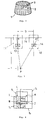
- Fig.2 shows a truncated cone 1 as an example of a 3-dimensional configuration to be recognized.
- checker pattern 2 is projected onto the surface of the above truncated cone 1, according to the present embodiment.
- the surface shape of the above truncated cone 1 is recognized by calculating 3-dimensional coordinates of cross points of the above checker pattern 2.
- Fig. 3 shows two typical cameras 11 and 12 for detecting 2-dimensional coordinate of cross points 3 on the surface.
- the above cameras form an image of a point P to be detected onto the screen 15 by the lenses 13 and 14.
- Fig.1 shows the procedure for the recognition of the configuration of the surface.
- a black spot is projected as a reference point onto the surface to be recognized. This reference point is used for obtaining 3-dimensional coordinates of each point on the surface at step 61.
- shaping correction is performed for the image obtained by cameras 11 and 12. Shading correction is performed so as to unify the luminance distribution of the whole image, as is generally known. Input image is segmented into a plurality of areas and optimized theresholds are calculated for each area so that the imae has equivalent luminance as a whole.
- step 52 smoothing processing, i.e., median filter, etc., is performed so as to perform noise processing with preserving edges. As the result, noises of an image is deleted without dulling edge.
- image is binarized at step 53 so that numerical value of "1" of "0” is given to all pixels as their luminance.
- the coordinate of a centroid of a spot projected onto the reference point is calculated for detecting the position of the reference point obtained at step 50.
- This position of the centroid is calculated, as is generally known, by dividing the moment around the predetermined point of a spot by the area of the spot.
- checker pattern is projected onto the surface of the solid.
- This checker pattern is formed, for example, by a meshed material in front of an iluminant and projecting the mesh pattern onto the surface. That is, this checker pattern is drawn with black lines onto the surface.
- Shading correction is performed for the above obtained checker pattern at step 56, and noise reduction and binarizing are performed at step 57 and 58, respectively.
- processings performed at steps 56, 57 and 58 are the same as that of steps 51, 52 and 53.
- thinning is performed for the checker pattern obtained from the processings up to steps 58.
- a configuration is converted into a line configuration with one pixel width by the above thinning.
- branch points are extracted from the thinned checker pattern. These branch points are extracted through, for example, evaluating eight pixels surrounding a center pixel with pixel value of "1" in the convolution of a size of 3x3.
- step 61 relationship between each point to the reference point is obtained. This is fully described with referring Fig.4.
- a convolution T1 is taken into a consideration with its center on the reference point B, arranging 5 pixels in vertical direction and 5 pixels in horizontal direction.
- Two cameras 11 and 12 (refer to Fig. 3) detect branch points on the above convolution T1, as examining each pixel successively in a spiral order, staring from the reference point B, as shown by an arrow in Fig.4.
- the locations of branch points detected by each camera 11, 12 are stored in a memory, which is not shown in the figure, as the relative location to the reference point B. That is, two cameras 11 and 12 define the relationship between equivalent points to each other.
- a 5x5 convolution T2 is taken into a consideration as described above, with its center of a branch point I which has already been detected.
- branch points are detected by examining pixels successively in a spiral order.
- branch points I, J, K and L fro which branch point J is detected first.
- the same branch point detection with respect to the next convolution T3 centering the branch point J is repeatedly performed.
- branch point detection with respect to the convolution T4 centering a branch point K in the convolution T2 is performed.
- no branch point is detecté ed with respect to a 5x5 convolution, a 10x10 convolution is taken and same branch point detection is performed.
- branch point detection for all pixels is performed so that the locations of all branch points are to be stored in a memory.
- step 62 3-dimensional coordinate for each branch point is calculated.
- the locations of each branch point detected by each camera 11, 12 are stored as the angles ⁇ and ⁇ as shown in Fig.3.
- distance L Z coordinate
- x and y coordinates are simply calculated by detecting the locations of each pixel, since a plane (x-y plane) perpendicular to the direction of distance L is parallel to a screen 15, and is on the same plane as that of the above convolution.
- x, y and z coordinates of each branch point i.e., cross points of the checker pattern, are calculated so as to recognize the surface shape of a 3-dimensional configuration.
Abstract
a means for projecting a checker pattern onto a surface of a solid object; a means for thinning said checker pattern and for generating a thinned checker pattern; a coupled of means for detecting 2-dimensional coordinate of said cross points; and a means for calculating 3-dimensional coordinate of said cross points from said 2-dimensional coordinate and positions of said couple of means.
Description
- The present invention relates to a 3-dimensional configuration recognition system for the recognition of a 3-dimensional surface.
- Conventionally, a system which obtains 3-dimensional coordinates of a surface of a solid from a light projected onto the surface, is known as a recognition system of a 3-dimensional configuration. In the above system, the light is emitted through slits and is moved over the surface. The location of the above light is detected by two cameras during this movement. The location of the light, i.e., 3-dimensional coordinates of the surface is calculated geometrically from the distance between 2 cameras and an angle formed with a line connecting the above cameras and a ray of light.
- As to such conventional 3-dimensional configuration recogni tion system, transit speed of a light should be lower than a predetermined value for accurate detection of the location of a light at the surface. Therefore, recognition speed is limited.
- The present invention is invented in view of the above points of the prior art and has an object to provide a system recognizable of 3-dimensional configuration at a high speed.
- A 3-dimensional configuration recognition system according to the present invention comprises:
a means for projecting a checker pattern onto a surface of a solid object;
a means for thinning said checker pattern and for generating a thinned checker pattern;
a means for extracting cross points of said thinned checker pattern;
a coupled of means for detecting 2-dimensional coordinate of said cross points; and
a means for calculating 3-dimensional coordinate of said cross points from said 2-dimensional coordinate and positions of said couple of means. -
- Fig.1 shows a flow chart showing the procedure of the recognition of the surface shape of a 3-dimensional configuration;
- Fig.2 shows a squint diagram showing an example of a 3-dimensional configuration to be recognized;
- Fig.3 shows a diagram showing the arrangement of cameras;
- Fig.4 shows a diagram showing the branch point detection processing.
- 2.....Checker Pattern
- 3.....Cross Point
- Hereinafter, an embodiment of the present invention is described with referring to the attached drawings.
- Fig.2 shows a truncated cone 1 as an example of a 3-dimensional configuration to be recognized. As it is described later,
checker pattern 2 is projected onto the surface of the above truncated cone 1, according to the present embodiment. The surface shape of the above truncated cone 1 is recognized by calculating 3-dimensional coordinates of cross points of theabove checker pattern 2. - Fig. 3 shows two
typical cameras cross points 3 on the surface. The above cameras form an image of a point P to be detected onto thescreen 15 by thelenses
L cotα + L cotβ = D
where distance betwen centers oflenses screen 15 to a point P is L; an angle formed with a line connecting a center point of alens 13 and a point P and a side of thescreen 15 is α; and an angle formed with a line connecting a center point of alens 14 and a point P and a side of thescreen 15 is β. Then distance L is calculated by the following formula:
L = D / (cotα + cotβ) (1)
This distance L is used atstep 62 for detecting 3-dimensional coordinates, as it is described hereinafter. - Fig.1 shows the procedure for the recognition of the configuration of the surface.
- At
step 50, a black spot is projected as a reference point onto the surface to be recognized. This reference point is used for obtaining 3-dimensional coordinates of each point on the surface atstep 61. - At
step 51, shaping correction is performed for the image obtained bycameras - At
step 52, smoothing processing, i.e., median filter, etc., is performed so as to perform noise processing with preserving edges. As the result, noises of an image is deleted without dulling edge. Such image is binarized atstep 53 so that numerical value of "1" of "0" is given to all pixels as their luminance. - At
step 54, the coordinate of a centroid of a spot projected onto the reference point is calculated for detecting the position of the reference point obtained atstep 50. This position of the centroid is calculated, as is generally known, by dividing the moment around the predetermined point of a spot by the area of the spot. - At
step 55, checker pattern is projected onto the surface of the solid. This checker pattern is formed, for example, by a meshed material in front of an iluminant and projecting the mesh pattern onto the surface. That is, this checker pattern is drawn with black lines onto the surface. - Shading correction is performed for the above obtained checker pattern at
step 56, and noise reduction and binarizing are performed atstep steps steps - At
step 59, thinning is performed for the checker pattern obtained from the processings up tosteps 58. A configuration is converted into a line configuration with one pixel width by the above thinning. - At
step 60, branch points are extracted from the thinned checker pattern. These branch points are extracted through, for example, evaluating eight pixels surrounding a center pixel with pixel value of "1" in the convolution of a size of 3x3. - At
step 61, relationship between each point to the reference point is obtained. This is fully described with referring Fig.4. - First, a convolution T1 is taken into a consideration with its center on the reference point B, arranging 5 pixels in vertical direction and 5 pixels in horizontal direction. Two
cameras 11 and 12 (refer to Fig. 3) detect branch points on the above convolution T1, as examining each pixel successively in a spiral order, staring from the reference point B, as shown by an arrow in Fig.4. The locations of branch points detected by eachcamera cameras - Next, a 5x5 convolution T2 is taken into a consideration as described above, with its center of a branch point I which has already been detected. According to this convolution T2, branch points are detected by examining pixels successively in a spiral order. Here it is assumed that there are 4 branch points I, J, K and L, fro which branch point J is detected first. In this case, the same branch point detection with respect to the next convolution T3 centering the branch point J is repeatedly performed. When any new branch point would not be discovered within the convolution T3, branch point detection with respect to the convolution T4 centering a branch point K in the convolution T2 is performed. On the other hand, when no branch point is detecté ed with respect to a 5x5 convolution, a 10x10 convolution is taken and same branch point detection is performed.
- By repeating the above processing, branch point detection for all pixels is performed so that the locations of all branch points are to be stored in a memory.
- At
step 62, 3-dimensional coordinate for each branch point is calculated. According to step 61, the locations of each branch point detected by eachcamera step 62, distance L (Z coordinate) is calculated by inputting the values of the above angles α and β into the above formula. On the other hand, x and y coordinates are simply calculated by detecting the locations of each pixel, since a plane (x-y plane) perpendicular to the direction of distance L is parallel to ascreen 15, and is on the same plane as that of the above convolution. - Accordingly, x, y and z coordinates of each branch point, i.e., cross points of the checker pattern, are calculated so as to recognize the surface shape of a 3-dimensional configuration.
- According to the present invention, as mentioned above, it is possible to obtain the advantage that a high speed recognition of 3-dimensional configuration becomes possible.
Claims (1)
- (1) A 3-dmensional configuration recognition system comprising:
a means for projecting a checker pattern onto a surface of a solide object;
a means for thinning said checker pattern and for generating a thinned checker pattern;
a means for extracting cross points of said thinned checker pattern;
a couple of means for detecting 2-dimensional coordinate of said cross points; and
a means for calculating 3-dimensional coordinate of said cross points from said 2-dimensional coordinate and positions of said coupled of means.
Applications Claiming Priority (2)
| Application Number | Priority Date | Filing Date | Title |
|---|---|---|---|
| JP1296677A JP2787149B2 (en) | 1989-11-15 | 1989-11-15 | 3D shape recognition device |
| JP296677/89 | 1989-11-15 |
Publications (2)
| Publication Number | Publication Date |
|---|---|
| EP0428082A2 true EP0428082A2 (en) | 1991-05-22 |
| EP0428082A3 EP0428082A3 (en) | 1993-05-26 |
Family
ID=17836648
Family Applications (1)
| Application Number | Title | Priority Date | Filing Date |
|---|---|---|---|
| EP19900121493 Withdrawn EP0428082A3 (en) | 1989-11-15 | 1990-11-09 | A 3-dimensional configuration recognition system |
Country Status (3)
| Country | Link |
|---|---|
| EP (1) | EP0428082A3 (en) |
| JP (1) | JP2787149B2 (en) |
| KR (1) | KR910010355A (en) |
Families Citing this family (2)
| Publication number | Priority date | Publication date | Assignee | Title |
|---|---|---|---|---|
| JP2980493B2 (en) * | 1993-08-19 | 1999-11-22 | インターナショナル・ビジネス・マシーンズ・コーポレイション | Measurement method of flying height of magnetic head |
| KR100972640B1 (en) * | 2008-05-07 | 2010-07-30 | 선문대학교 산학협력단 | reference grating for acquire method and apparatus for measuring three-dimensional using moire |
Citations (1)
| Publication number | Priority date | Publication date | Assignee | Title |
|---|---|---|---|---|
| US4842411A (en) * | 1986-02-06 | 1989-06-27 | Vectron, Inc. | Method of automatically measuring the shape of a continuous surface |
Family Cites Families (3)
| Publication number | Priority date | Publication date | Assignee | Title |
|---|---|---|---|---|
| JPS5278467A (en) * | 1975-12-25 | 1977-07-01 | Agency Of Ind Science & Technol | Method of determining reference points for measurement of configuratio n |
| JPH061164B2 (en) * | 1985-01-31 | 1994-01-05 | 伍良 松本 | Three-dimensional shape measuring device |
| JP2739319B2 (en) * | 1988-03-01 | 1998-04-15 | 株式会社エイ・ティ・アール通信システム研究所 | 3D shape reproduction device |
-
1989
- 1989-11-15 JP JP1296677A patent/JP2787149B2/en not_active Expired - Fee Related
-
1990
- 1990-11-06 KR KR1019900017904A patent/KR910010355A/en not_active Application Discontinuation
- 1990-11-09 EP EP19900121493 patent/EP0428082A3/en not_active Withdrawn
Patent Citations (1)
| Publication number | Priority date | Publication date | Assignee | Title |
|---|---|---|---|---|
| US4842411A (en) * | 1986-02-06 | 1989-06-27 | Vectron, Inc. | Method of automatically measuring the shape of a continuous surface |
Non-Patent Citations (2)
| Title |
|---|
| PROCEEDINGS OF THE FIFTEENTH ANNUAL NORTHEAST BIOENGINEERING CONFERENCE , MARCH 27-28 ,1989 ,BOSTON,MA (US) pages 115 - 116 , XP41665 KEI HOI CHEUNG ET AL. 'three-dimensional reconstruction of the craniofacial surface with stereopair images' * |
| SYSTEMS & COMPUTERS IN JAPAN vol. 20, no. 7, July 1989, NEW YORK US pages 53 - 60 , XP116728 YOSHIHARU YUBA ET AL. 'rotated checker-pattern projection and its cross-point extraction and tracking for 3d object profilometry' * |
Also Published As
| Publication number | Publication date |
|---|---|
| JPH03158709A (en) | 1991-07-08 |
| EP0428082A3 (en) | 1993-05-26 |
| JP2787149B2 (en) | 1998-08-13 |
| KR910010355A (en) | 1991-06-29 |
Similar Documents
| Publication | Publication Date | Title |
|---|---|---|
| US5231678A (en) | Configuration recognition system calculating a three-dimensional distance to an object by detecting cross points projected on the object | |
| US5081689A (en) | Apparatus and method for extracting edges and lines | |
| EP0523152B1 (en) | Real time three dimensional sensing system | |
| US7650015B2 (en) | Image processing method | |
| KR100643305B1 (en) | Method and apparatus for processing line pattern using convolution kernel | |
| JPH07113966B2 (en) | Two-dimensional image processing method and apparatus | |
| CN113838141B (en) | External parameter calibration method and system for single-line laser radar and visible light camera | |
| US6396960B1 (en) | Method and apparatus of image composite processing | |
| EP0157299A1 (en) | Image processing apparatus | |
| GB2410794A (en) | Apparatus and methods for three dimensional scanning | |
| EP0428082A2 (en) | A 3-dimensional configuration recognition system | |
| JP3516118B2 (en) | Object recognition method and object recognition device | |
| JP3627249B2 (en) | Image processing device | |
| GB2272285A (en) | Determining the position of edges and corners in images. | |
| EP0493105A2 (en) | Data processing method and apparatus | |
| JPH10283478A (en) | Method for extracting feature and and device for recognizing object using the same method | |
| JPH0560518A (en) | Three-dimensional coordinate measurement device | |
| JP2004030453A (en) | Stereo matching method, stereo matching program, and computer readable recording medium with stereo matching program recorded thereon | |
| US20020159654A1 (en) | Method for processing an image of a concrete construction | |
| JPS59188509A (en) | Recognition system of position and shape of body | |
| JPH05272922A (en) | Visual sensor apparatus | |
| JPH047805B2 (en) | ||
| JP2959017B2 (en) | Circular image discrimination method | |
| JP3080097B2 (en) | Parallel line figure extraction method | |
| JPH0624028B2 (en) | Position measurement method of feature point corners for pattern recognition |
Legal Events
| Date | Code | Title | Description |
|---|---|---|---|
| PUAI | Public reference made under article 153(3) epc to a published international application that has entered the european phase |
Free format text: ORIGINAL CODE: 0009012 |
|
| AK | Designated contracting states |
Kind code of ref document: A2 Designated state(s): BE DE FR GB IT NL SE |
|
| PUAL | Search report despatched |
Free format text: ORIGINAL CODE: 0009013 |
|
| AK | Designated contracting states |
Kind code of ref document: A3 Designated state(s): BE DE FR GB IT NL SE |
|
| 17P | Request for examination filed |
Effective date: 19930505 |
|
| RAP1 | Party data changed (applicant data changed or rights of an application transferred) |
Owner name: EZEL INC. Owner name: SHARP KABUSHIKI KAISHA |
|
| RAP1 | Party data changed (applicant data changed or rights of an application transferred) |
Owner name: SHARP KABUSHIKI KAISHA Owner name: EZEL INC. |
|
| RAP3 | Party data changed (applicant data changed or rights of an application transferred) |
Owner name: EZEL INC. Owner name: SHARP KABUSHIKI KAISHA |
|
| 17Q | First examination report despatched |
Effective date: 19940120 |
|
| STAA | Information on the status of an ep patent application or granted ep patent |
Free format text: STATUS: THE APPLICATION IS DEEMED TO BE WITHDRAWN |
|
| 18D | Application deemed to be withdrawn |
Effective date: 19950329 |