EP0428078A2 - Circuit à modulation de largeur d'impulsion pour l'actionnement d'une charge - Google Patents
Circuit à modulation de largeur d'impulsion pour l'actionnement d'une charge Download PDFInfo
- Publication number
- EP0428078A2 EP0428078A2 EP90121462A EP90121462A EP0428078A2 EP 0428078 A2 EP0428078 A2 EP 0428078A2 EP 90121462 A EP90121462 A EP 90121462A EP 90121462 A EP90121462 A EP 90121462A EP 0428078 A2 EP0428078 A2 EP 0428078A2
- Authority
- EP
- European Patent Office
- Prior art keywords
- load
- voltage
- pulse
- pulse trains
- circuit
- Prior art date
- Legal status (The legal status is an assumption and is not a legal conclusion. Google has not performed a legal analysis and makes no representation as to the accuracy of the status listed.)
- Withdrawn
Links
Images


Classifications
-
- H—ELECTRICITY
- H02—GENERATION; CONVERSION OR DISTRIBUTION OF ELECTRIC POWER
- H02M—APPARATUS FOR CONVERSION BETWEEN AC AND AC, BETWEEN AC AND DC, OR BETWEEN DC AND DC, AND FOR USE WITH MAINS OR SIMILAR POWER SUPPLY SYSTEMS; CONVERSION OF DC OR AC INPUT POWER INTO SURGE OUTPUT POWER; CONTROL OR REGULATION THEREOF
- H02M7/00—Conversion of ac power input into dc power output; Conversion of dc power input into ac power output
- H02M7/42—Conversion of dc power input into ac power output without possibility of reversal
- H02M7/44—Conversion of dc power input into ac power output without possibility of reversal by static converters
- H02M7/48—Conversion of dc power input into ac power output without possibility of reversal by static converters using discharge tubes with control electrode or semiconductor devices with control electrode
- H02M7/53—Conversion of dc power input into ac power output without possibility of reversal by static converters using discharge tubes with control electrode or semiconductor devices with control electrode using devices of a triode or transistor type requiring continuous application of a control signal
- H02M7/537—Conversion of dc power input into ac power output without possibility of reversal by static converters using discharge tubes with control electrode or semiconductor devices with control electrode using devices of a triode or transistor type requiring continuous application of a control signal using semiconductor devices only, e.g. single switched pulse inverters
- H02M7/5387—Conversion of dc power input into ac power output without possibility of reversal by static converters using discharge tubes with control electrode or semiconductor devices with control electrode using devices of a triode or transistor type requiring continuous application of a control signal using semiconductor devices only, e.g. single switched pulse inverters in a bridge configuration
Definitions
- This invention relates to the field of pulse-width modulation systems for causing currents to flow through a load in response to a command signal.
- the invention is particularly useful in the field of motion control, such as in servo-amplifiers, brushless motors, and the like.
- Linear power amplifiers have been used for increasing the level of the error signal, so as to provide a signal capable of driving the motor.
- linear amplifiers dissipate power, and this power dissipation substantially reduces the efficiency of the system.
- a system which dissipates power must be provided with heat sinks, cooling fans, and similar apparatus, and the system's size and weight is therefore increased.
- the energy used to develop the power dissipated in the amplifier is wasted, increasing the overall cost of operation.
- excessive heat is known to shorten the useful lives of the semiconductor devices used in the amplifier.
- a pulse-width modulated (PWM) circuit achieves this goal.
- the command signal is used to generate a train of pulses, the width of each pulse being related to the instantaneous value of the command signal.
- the pulses are generated by using a comparator to compare the command signal with a dither signal, which is a sawtooth or triangular wave. When the command signal exceeds the dither signal, the output of the comparator is high; at other times, the output of the comparator is low. The comparator output thus comprises the train of pulses representing the command signal.
- the pulses are then used to drive an electronic switching device, such as one or more transistors, for intermittently applying a voltage across the load.
- transistors When transistors are used as switches, they are either fully on (i.e. saturated) or fully off (“cut-off"). Thus, virtually no power is dissipated in the transistors, because when the transistors are saturated, there is almost no voltage drop, and when they are cut-off, there is negligible current flow.
- a PWM circuit comprises a switch for applying the voltage of the power supply across the load, wherein the switch does not itself consume appreciable power.
- transistor switches do consume small amounts of power, because they are never totally cut-off or resistance-free. But the efficiency of a PWM circuit can be as high as about 90-95%, compared with only about 40% for linear amplifiers.
- the magnitude of the ripple is directly proportional to the supply voltage and inversely proportional to the switching frequency and the inductance of the motor.
- the inductance of the motor and the power supply voltage are fixed. The easiest way of reducing the ripple is therefore to increase the switching frequency. However, doing so increases switching losses in the transistor switches.
- the amount of ripple is further increased by the fact that, in PWM circuits of the prior art, the maximum voltage excursion is twice the magnitude of the supply voltage. Thus, if the supply voltage is designated as V , the switching network which produces the pulses alternately applies voltages of + V and - V across the load. Thus, the maximum excursion is 2 V . The greater the voltage excursion, the greater the current ripple.
- the ripple current waveform has both an average value and an rms value.
- the motor can respond only to the average current. If the current has any ripple, the rms value is larger than the average value.
- the difference between the rms current and the average current contributes only to wasteful heating of the motor, thus reducing efficiency.
- the average and rms currents must be equal. This condition occurs only when there is no ripple, i.e. then there is a constant DC waveform.
- the present invention provides a circuit which, for a given basic frequency of the dither signal, and a given magnitude of the supply volt age, produces a PWM signal which reduces current ripple by a factor of four, as compared with comparable PWM circuits of the prior art.
- the invention comprises a unique double bridge circuit which forms alternate electrical paths for applying a voltage of the desired polarity across the load, at any given instant.
- the apparatus of the present invention includes two bridge circuits, connected together, both bridge circuits being connected to the load.
- Both bridge circuits comprise a set of switches, preferably electronic switches such as transistors.
- the inputs to the switches comprise electronic pulses which turn the switches on and off, and which thereby open and close various electrical paths for applying a voltage to the load.
- the pulses applied to the electronic switches are generated from the command signal.
- the absolute value of the command signal is compared with a dither signal, which is preferably a triangular wave, and a pulse is generated whenever the command signal exceeds the dither signal.
- the inverse of the command signal is similarly compared with the dither signal, and the inverted output of this comparison produces another train of pulses.
- the complements of both of these pulse trains are also obtained, and are applied to some of the various electronic switches in the bridges.
- the bridges comprise logic circuitry for applying voltage across the load in response to various conditions of the input pulses.
- the bridges are connected such that, at certain moments, their respective contributions to the voltage applied across the load cancel each other, and, at other moments, the contributions have the same polarity. The net result is that the voltage applied across the load is zero during those moments when a pulse is present in either of the original two pulse trains, and is equal to the supply voltage at all other times.
- the effective frequency of the voltage pulses applied to the load is twice that of comparable PWM circuits of the prior art. Also, because both bridges connect the load to the same power supply, the maximum voltage excursion can never be more than the magnitude of the supply voltage. This maximum excursion is one-half the excursion of comparable PWM circuits of the prior art. Since the amount of current ripple in the load is proportional to the frequency and to the voltage excursion, the circuit of the present invention effectively reduces the amount of ripple by a factor of four, when compared to a PWM circuit having a similarly rated power supply and a dither signal of similar frequency.
- PWM pulse-width modulated
- Figure 1 shows a set of waveforms which illustrate the operation of the circuit of the present invention.
- the circuit itself is shown, in schematic form, in Figures 2 and 3.
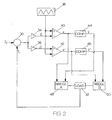
- Figure 2 shows the general arrangement of a servo-amplifier feedback loop, as modified to incorporate the present invention.
- Command current signal I c is combined with current signal i L from load 32, in summing circuit 30.
- the combined current signal is passed through amplifiers 34 and 36, amplifier 36 being an inverting amplifier, as shown.
- the signals from amplifiers 34 and 36 are fed to comparators 40 and 42, respectively, where they are compared with a dither signal, having a sawtooth or triangular shape, produced by sawtooth wave generator 38.
- the negative of the current signal (-I), taken from amplifier 36, is compared with the dither signal, in comparator 42.
- the dither signal is connected to the inverting input of comparator 42. The connection is such that when the dither signal is less than the negative current signal (-I), the output of the comparator becomes high.
- the output of comparator 42 is the pulse train shown in Figure 1c. This pulse train is called signal x ′.
- the Figures 1b and 1c are drawn to the same voltage scale. It should be noted that signals x and x ′ are independent signals, and are not necessarily mirror images of each other. The latter statement is true because the command current signal, in general, varies with time.
- the signals x and x ′ are passed through complementing circuits 44 and 46, to generate signals y and y ′, respectively.
- the latter signals are illustrated In Figures 1d and 1e, respectively. These signals are strictly dependent on signals x and x ′, because they are obtained only by complementation.
- FIG. 3 shows the bridge circuits represented in block form in Figure 2.
- the bridge circuits are connected across one power supply, having a voltage of V .
- V and v need not be equal; normally, V , the voltage ultimately applied across the load, is much greater than v , the amplitude of the control pulses.
- Bridge A includes switches 60, 62, 64, and 66. These switches are preferably electronic switches, such as transistors.
- Bridge B includes switches 68, 70, 72, and 74, preferably similar to the switches of bridge A.
- Load 32 is connected to the two bridge circuits, through inductors 76, 78, 80; and 82.
- the load may be a motor, or any other inductive or resistive load.
- each of the switches of bridge A is controlled by one of the signals x or y .
- Each of the switches of bridge B is controlled by one of the signals x ′ or y ′.
- bridge B places a negative voltage (- V ) across the load, because it connects the power supply to the load in the opposite direction from bridge A.
- the effect of bridge B is shown in Figure 1g.
- the net effect of the two bridges is shown in Figure 1h.
- the load "sees" zero volts in Case 2.
- the dither signal is negative, and has an absolute value greater than that of the command signal.
- Signal x is low and signal x ′ is high.
- signal y is high and signal y ′ is low.
- the only closed switches are now switches 60, 66, 68, and 74.
- the circuit path through bridge A includes switch 60, inductor 80, load 32, inductor 76, and switch 66.
- the load therefore "sees" a voltage of - V due to bridge A, as shown in Figure 1f.
- the circuit path through bridge B includes switch 68, inductor 78, load 32, inductor 82, and switch 74.
- the load therefore sees a voltage of + V due to bridge B, as shown in Figure 1g.
- the net effect of the two bridges is that the load "sees" zero volts, as shown in Figure 1h.
- the inductors are necessary to prevent short circuits in Cases 2 and 4.
- Case 2 for example, without the inductors, there would be a direct path from the power supply (+ V ), through switch 64, switch 70, and back to the power supply. There would also be a short circuit through switches 72 and 62.
- Case 4 without the inductors there would be a short circuit from the power supply (+ V ) through switch 60, through switch 74, and back to the power supply.
- switches 68 and 66 As long as the frequency of pulses is sufficiently high that the period of the pulses is less than the time constant of the inductors, the inductors will prevent short circuits.
- the frequency of pulses in Figure 1h is twice the frequency of pulses in signal x .
- Signal x is equivalent to a PWM signal of the prior art.
- the circuit of the present invention doubles the frequency of the resultant PWM signal applied to the load.
- the maximum voltage excursion of the signal in Figure 1h is V , i.e. the magnitude of the supply voltage, not 2 V as is true in the prior art.
- the present invention achieves a reduction in ripple by a factor of four.
- the effective bandwidth of the PWM circuit of the present invention is therefore much greater than in PWM circuits of the prior art.
- the present invention avoids the undesirable switching losses that would be incurred by simply increasing the frequency of the dither signal.
- the switches are controlled separately by the signals x , x ′, y , and y ′. All of these signals, taken separately, have a frequency which is one-half that of the waveform of Figure 1h. Thus, the switches are not driven at excessive switching rates. But it is the high-frequency waveform of Figure 1h which is "seen" by the load.
- inductors 76 and 78 are magnetically coupled, but wound in an opposed sense.
- the same is true for the pair of inductors 80 and 82, although the inductors of one pair are not magnetically coupled to the inductors of the other pair.
- the magnetic coupling of the pairs of inductors may be most easily accomplished by winding both inductors of a pair on the same core.
- the electrical connections are otherwise the same as shown in Figure 3. This arrangement gives the system a greater usable bandwidth because, when the bridges are delivering power, the inductive effects tend to cancel. For a given amplifier gain and supply voltage, the bandwidth is limited only by the load itself.
- the invention can be practiced without winding the inductors as stated above, but with reduced bandwidth.
- FIG 4 is a schematic diagram showing the use of the present in vention in driving a three-phase brushless motor.
- the three windings of the brushless motor are designated by reference numerals 61, 62, and 63.
- Each winding is connected to a bridge circuit, designated generally by reference numerals 71, 72, and 73, respectively.
- Each of the bridge circuits is similar to that shown in Figure 3, except that there are only four switches and two inductors in each bridge. It turns out that, because the windings are all connected at one point, each pair of bridges in Figure 4 is electrically equivalent to the full bridge of Figure 3.
- the dotted line 75 illustrates symbolically that the motor shaft (not shown) is connected to an encoder 76.
- the output of the encoder is connected to a suitable logic circuit which controls a current command circuit 78.
- Circuit 78 accepts, as input, the command current, and generates three command currents as outputs. These command currents comprise the command "subsignals" for each bridge.
- the command currents are used to generate three separate trains of pulses, in the manner described in connection with Figures 1 and 2, and the pulses are used to control the bridges in a similar manner.
- the pulses are generated, and applied to the switches of each bridge, substantially simultaneously.
- the invention can also be used with a switching power supply. That is, the bridge circuit of the present invention could be used to drive a transformer instead of a motor, and the control voltage could be fixed or variable.
- the present invention can be modified in various other ways.
- the electronic switches can be replaced with equivalent devices.
- the invention need not be limited to the particular bridge topologies described herein, but may include other ways of implementing the method represented in Figure 1.
- the PWM circuit be capable of determining whether the absolute value of the dither signal is greater or less than that of the command signal.
- the output of a circuit which determines these conditions could be used to produce a voltage across the load.
- a first voltage would be applied across the load when the absolute value of the dither signal is greater than that of the command signal; a second voltage, having a different value, would be applied when the absolute value of the dither signal is less than that of the command signal.
- the first voltage is - V
- the second voltage is zero.
Applications Claiming Priority (2)
| Application Number | Priority Date | Filing Date | Title |
|---|---|---|---|
| US435258 | 1989-11-13 | ||
| US07/435,258 US5070292A (en) | 1989-11-13 | 1989-11-13 | Pulse-width modulated circuit for driving a load |
Publications (2)
| Publication Number | Publication Date |
|---|---|
| EP0428078A2 true EP0428078A2 (fr) | 1991-05-22 |
| EP0428078A3 EP0428078A3 (en) | 1991-10-23 |
Family
ID=23727683
Family Applications (1)
| Application Number | Title | Priority Date | Filing Date |
|---|---|---|---|
| EP19900121462 Withdrawn EP0428078A3 (en) | 1989-11-13 | 1990-11-09 | Pulse-width modulated circuit for driving a load |
Country Status (2)
| Country | Link |
|---|---|
| US (1) | US5070292A (fr) |
| EP (1) | EP0428078A3 (fr) |
Cited By (1)
| Publication number | Priority date | Publication date | Assignee | Title |
|---|---|---|---|---|
| DE10013672A1 (de) * | 2000-03-20 | 2001-10-18 | Siemens Ag | Stromrichterschaltung |
Families Citing this family (21)
| Publication number | Priority date | Publication date | Assignee | Title |
|---|---|---|---|---|
| US5162987A (en) * | 1990-12-28 | 1992-11-10 | Leslie Controls, Inc. | Controller which uses pulse width and pulse frequency modulated signals to control a variable |
| US5399908A (en) * | 1992-06-26 | 1995-03-21 | Kollmorgen Corporation | Apparatus and method for forced sharing of parallel MOSFET switching losses |
| US5379209A (en) * | 1993-02-09 | 1995-01-03 | Performance Controls, Inc. | Electronic switching circuit |
| US5493487A (en) * | 1993-02-09 | 1996-02-20 | Performance Controls, Inc. | Electronic switching circuit |
| US5365422A (en) * | 1993-06-01 | 1994-11-15 | Performance Controls, Inc. | Pulse-width modulated circuit for applying current to a load |
| US5497062A (en) * | 1993-09-20 | 1996-03-05 | Performance Controls, Inc. | Digital pulse-width modulated system for providing current to a load |
| US5625545A (en) * | 1994-03-01 | 1997-04-29 | Halmar Robicon Group | Medium voltage PWM drive and method |
| US5619112A (en) * | 1995-02-09 | 1997-04-08 | Woodward Governor Company | Bi-directional electric torque motor and driver |
| US5629616A (en) * | 1995-07-13 | 1997-05-13 | Performance Conrols, Inc. | Circuit for measuring current in class-d amplifiers |
| US5646837A (en) * | 1995-12-19 | 1997-07-08 | Performance Controls, Inc. | Pulse-width modulated circuit with improved linearity |
| DE19702949A1 (de) * | 1997-01-28 | 1998-07-30 | Stribel Gmbh | Steuergerät |
| EP1171776A4 (fr) | 1998-11-30 | 2003-07-09 | Mts System Corp | Circuit avec reponse dynamique amelioree pour mesurer le courant dans des amplificateurs modules en largeur d'impulsion |
| US6353354B1 (en) | 1999-09-28 | 2002-03-05 | Mts Systems Corporation | Pulse-width modulated bridge circuit within a second bridge circuit |
| US6534967B1 (en) | 2000-09-25 | 2003-03-18 | Mts Systems Corporation | Dual totem current sensor for measuring load current in an H-bridge power stage |
| US7027743B1 (en) * | 2000-10-05 | 2006-04-11 | Agilent Technologies, Inc. | System and method for optical heterodyne detection of an optical signal including optical pre-selection that is adjusted to accurately track a local oscillator signal |
| US8604709B2 (en) | 2007-07-31 | 2013-12-10 | Lsi Industries, Inc. | Methods and systems for controlling electrical power to DC loads |
| US8903577B2 (en) | 2009-10-30 | 2014-12-02 | Lsi Industries, Inc. | Traction system for electrically powered vehicles |
| US7598683B1 (en) | 2007-07-31 | 2009-10-06 | Lsi Industries, Inc. | Control of light intensity using pulses of a fixed duration and frequency |
| US8054021B2 (en) * | 2007-10-31 | 2011-11-08 | Hewlett-Packard Development Company, L.P. | Programmable motor drive |
| CN107861019B (zh) * | 2017-11-23 | 2023-09-05 | 深圳市巴丁微电子有限公司 | 一种h桥的检测系统及检测方法 |
| CN110995181B (zh) * | 2019-12-31 | 2023-03-24 | 湖南迈太科医疗科技有限公司 | 梯度功率放大器 |
Citations (4)
| Publication number | Priority date | Publication date | Assignee | Title |
|---|---|---|---|---|
| EP0024300A1 (fr) * | 1979-07-30 | 1981-03-04 | Siemens Aktiengesellschaft | Procédé pour le contrôle de la durée d'impulsion d'un régulateur inverseur à courant continu et circuit pour la mise en oeuvre dudit procédé |
| EP0167806A1 (fr) * | 1984-06-08 | 1986-01-15 | Honeywell Bull Inc. | Traitement de défauts de matière de disques pour mémoire de masse |
| DE3433886A1 (de) * | 1984-09-14 | 1986-03-27 | Siemens AG, 1000 Berlin und 8000 München | Steuereinrichtung fuer einen gleichstrom-halbleitersteller |
| GB2204197A (en) * | 1987-04-22 | 1988-11-02 | I Soo Lee | Electronically commutated motor |
Family Cites Families (22)
| Publication number | Priority date | Publication date | Assignee | Title |
|---|---|---|---|---|
| KR900000643B1 (ko) * | 1959-03-26 | 1990-02-02 | 산요덴끼 가부시기가이샤 | 인버어터 장치 |
| US3260912A (en) * | 1963-06-19 | 1966-07-12 | Gen Motors Corp | Power amplifier employing pulse duration modulation |
| US3393363A (en) * | 1963-10-07 | 1968-07-16 | Forster Ind Inc | Amplifying means employing pulse width modulation |
| US3351873A (en) * | 1964-07-08 | 1967-11-07 | Hitachi Ltd | Analog to digital converter employing noise rejection signal modulator |
| US3535657A (en) * | 1967-09-13 | 1970-10-20 | Webb James E | Pulse-width modulation multiplier |
| US3849709A (en) * | 1973-04-25 | 1974-11-19 | Beeman H | Motor control system |
| US3883786A (en) * | 1973-10-12 | 1975-05-13 | Gen Electric | Pulse width modulated servo system |
| US4388579A (en) * | 1981-07-17 | 1983-06-14 | The United States Of America As Represented By The United States Department Of Energy | Control system for a wound-rotor motor |
| EP0077075B1 (fr) * | 1981-10-14 | 1986-07-16 | Hitachi, Ltd. | Lecteur numérique pour la reproduction d'une séquence de signals numérique |
| GB2140987B (en) * | 1983-04-15 | 1986-11-19 | Hitachi Ltd | Control apparatus for current type inverter |
| JPH07108095B2 (ja) * | 1984-01-20 | 1995-11-15 | 株式会社日立製作所 | インバータ装置及びその制御方法 |
| DE3573497D1 (de) * | 1984-03-08 | 1989-11-09 | Meidensha Electric Mfg Co Ltd | Digital pwmed pulse generator |
| US4882511A (en) * | 1984-06-01 | 1989-11-21 | Papst-Motoren Gmbh & Co. Kg | Brushless three-phase D.C. motor |
| US4584505A (en) * | 1984-06-14 | 1986-04-22 | Yeongchoon Chung | Torque-speed control system for asynchronous D.C. brushless motor |
| US4686436A (en) * | 1984-07-06 | 1987-08-11 | General Electric Company | Electronic control circuit, electronically commutated motor system and method for controlling same, laundry apparatus, and methods for operating apparatus for switching high voltage DC and for controlling electrical load powering apparatus |
| US4706180A (en) * | 1985-11-29 | 1987-11-10 | York International Corporation | Pulse width modulated inverter system for driving single phase a-c induction motor |
| US4626803A (en) * | 1985-12-30 | 1986-12-02 | General Electric Company | Apparatus for providing a carrier signal with two digital data streams I-Q modulated thereon |
| US4689802A (en) * | 1986-05-22 | 1987-08-25 | Chrysler Motors Corporation | Digital pulse width modulator |
| DE3619353A1 (de) * | 1986-06-09 | 1987-12-10 | Philips Patentverwaltung | Pulsbreitenmodulator |
| US4763059A (en) * | 1987-06-23 | 1988-08-09 | General Electric Company | Method and apparatus for induction motor drive |
| DE3744463C1 (en) * | 1987-12-23 | 1989-05-24 | Licentia Gmbh | Control method for a four-quadrant actuator (controller) |
| US4904919A (en) * | 1988-06-21 | 1990-02-27 | Allen-Bradley Company, Inc. | Dual mode control of a PWM motor drive for current limiting |
-
1989
- 1989-11-13 US US07/435,258 patent/US5070292A/en not_active Expired - Lifetime
-
1990
- 1990-11-09 EP EP19900121462 patent/EP0428078A3/en not_active Withdrawn
Patent Citations (4)
| Publication number | Priority date | Publication date | Assignee | Title |
|---|---|---|---|---|
| EP0024300A1 (fr) * | 1979-07-30 | 1981-03-04 | Siemens Aktiengesellschaft | Procédé pour le contrôle de la durée d'impulsion d'un régulateur inverseur à courant continu et circuit pour la mise en oeuvre dudit procédé |
| EP0167806A1 (fr) * | 1984-06-08 | 1986-01-15 | Honeywell Bull Inc. | Traitement de défauts de matière de disques pour mémoire de masse |
| DE3433886A1 (de) * | 1984-09-14 | 1986-03-27 | Siemens AG, 1000 Berlin und 8000 München | Steuereinrichtung fuer einen gleichstrom-halbleitersteller |
| GB2204197A (en) * | 1987-04-22 | 1988-11-02 | I Soo Lee | Electronically commutated motor |
Cited By (1)
| Publication number | Priority date | Publication date | Assignee | Title |
|---|---|---|---|---|
| DE10013672A1 (de) * | 2000-03-20 | 2001-10-18 | Siemens Ag | Stromrichterschaltung |
Also Published As
| Publication number | Publication date |
|---|---|
| EP0428078A3 (en) | 1991-10-23 |
| US5070292A (en) | 1991-12-03 |
Similar Documents
| Publication | Publication Date | Title |
|---|---|---|
| EP0428078A2 (fr) | Circuit à modulation de largeur d'impulsion pour l'actionnement d'une charge | |
| US5081409A (en) | Pulse-width modulated circuit for driving a load | |
| JP3634443B2 (ja) | 誘導性負荷用制御回路 | |
| EP0360854B1 (fr) | Appareil de commutation de puissance a deux etats, bilateral, a un seul pole, a deux directions et a demi-pont, et moyen d'alimentation de puissance pour un tel appareil de commutation | |
| JPH04190693A (ja) | インダクタンス負荷の通電制御回路 | |
| JPH06217547A (ja) | 電圧制御回路 | |
| US5519601A (en) | Pulse-width modulated circuit for applying current to a load | |
| WO1996012339A1 (fr) | Convertisseur resonant parallele a tension imposee et a facteur de marche ajustable | |
| JPH01122373A (ja) | 電源回路 | |
| JPH04229021A (ja) | 電力発生装置 | |
| KR930000416B1 (ko) | 유도성부하에 전원을 공급하는데 적합한 회로를 위한 제어장치 | |
| JPS62166772A (ja) | 電源を切り替える場合に使用される順変換装置 | |
| EP0783203B1 (fr) | Convertisseur de puissance en pont | |
| JP2003511005A (ja) | 第2のブリッジ回路内のパルス幅変調されたブリッジ回路 | |
| US6051959A (en) | Apparatus for resonant excitation of high frequency alternator field | |
| JP6401222B2 (ja) | 誘導負荷駆動回路 | |
| US5442276A (en) | Apparatus for providing controlled mechanical braking torque | |
| US4922397A (en) | Apparatus and method for a quasi-resonant DC to DC bridge converter | |
| JP6262835B1 (ja) | 誘導負荷駆動回路 | |
| US6856107B2 (en) | Linear-motion engine controller and related method | |
| GB2261333A (en) | Aircraft windshield heater system | |
| US20040062066A1 (en) | Switched mode circuit topologies | |
| US6028760A (en) | Resonant power converter for energizing a coil | |
| WO2005065181A2 (fr) | Convertisseur de puissance a synchronisation de commutation de sortie amelioree | |
| US5260645A (en) | Power supplies |
Legal Events
| Date | Code | Title | Description |
|---|---|---|---|
| PUAI | Public reference made under article 153(3) epc to a published international application that has entered the european phase |
Free format text: ORIGINAL CODE: 0009012 |
|
| AK | Designated contracting states |
Kind code of ref document: A2 Designated state(s): AT BE CH DE DK ES FR GB GR IT LI LU NL SE |
|
| PUAL | Search report despatched |
Free format text: ORIGINAL CODE: 0009013 |
|
| AK | Designated contracting states |
Kind code of ref document: A3 Designated state(s): AT BE CH DE DK ES FR GB GR IT LI LU NL SE |
|
| 16A | New documents despatched to applicant after publication of the search report | ||
| 17P | Request for examination filed |
Effective date: 19920401 |
|
| STAA | Information on the status of an ep patent application or granted ep patent |
Free format text: STATUS: THE APPLICATION IS DEEMED TO BE WITHDRAWN |
|
| 18D | Application deemed to be withdrawn |
Effective date: 19930602 |