EP0428027B1 - Optical distance measurement device - Google Patents
Optical distance measurement device Download PDFInfo
- Publication number
- EP0428027B1 EP0428027B1 EP90121050A EP90121050A EP0428027B1 EP 0428027 B1 EP0428027 B1 EP 0428027B1 EP 90121050 A EP90121050 A EP 90121050A EP 90121050 A EP90121050 A EP 90121050A EP 0428027 B1 EP0428027 B1 EP 0428027B1
- Authority
- EP
- European Patent Office
- Prior art keywords
- light
- laser
- frequency
- detector
- modes
- Prior art date
- Legal status (The legal status is an assumption and is not a legal conclusion. Google has not performed a legal analysis and makes no representation as to the accuracy of the status listed.)
- Expired - Lifetime
Links
Images
Classifications
-
- G—PHYSICS
- G01—MEASURING; TESTING
- G01S—RADIO DIRECTION-FINDING; RADIO NAVIGATION; DETERMINING DISTANCE OR VELOCITY BY USE OF RADIO WAVES; LOCATING OR PRESENCE-DETECTING BY USE OF THE REFLECTION OR RERADIATION OF RADIO WAVES; ANALOGOUS ARRANGEMENTS USING OTHER WAVES
- G01S17/00—Systems using the reflection or reradiation of electromagnetic waves other than radio waves, e.g. lidar systems
- G01S17/02—Systems using the reflection of electromagnetic waves other than radio waves
- G01S17/06—Systems determining position data of a target
- G01S17/08—Systems determining position data of a target for measuring distance only
- G01S17/32—Systems determining position data of a target for measuring distance only using transmission of continuous waves, whether amplitude-, frequency-, or phase-modulated, or unmodulated
- G01S17/36—Systems determining position data of a target for measuring distance only using transmission of continuous waves, whether amplitude-, frequency-, or phase-modulated, or unmodulated with phase comparison between the received signal and the contemporaneously transmitted signal
-
- G—PHYSICS
- G01—MEASURING; TESTING
- G01S—RADIO DIRECTION-FINDING; RADIO NAVIGATION; DETERMINING DISTANCE OR VELOCITY BY USE OF RADIO WAVES; LOCATING OR PRESENCE-DETECTING BY USE OF THE REFLECTION OR RERADIATION OF RADIO WAVES; ANALOGOUS ARRANGEMENTS USING OTHER WAVES
- G01S17/00—Systems using the reflection or reradiation of electromagnetic waves other than radio waves, e.g. lidar systems
- G01S17/87—Combinations of systems using electromagnetic waves other than radio waves
Definitions
- the invention relates to an optical distance measuring device according to the preamble of claim 1.
- a measuring device is described in Measurement Techniques, Volume 31, No. 5, 1988, pages 421-423.
- the detector signals of the light reflected from the measurement object and an internal reference beam path are each mixed down to a low frequency with a reference oscillation, which is generated electronically by a quartz oscillator.
- the phase measurement is then based on the signal at this down-mixed frequency.
- the device has a relative accuracy of 2x10 ⁇ 6 at a measuring distance of up to 30 m.
- the applicant's electronic tachymeter represents measuring devices which have a relatively simple optical structure.
- a luminescence diode operated via an oscillator and an amplifier generates an amplitude-modulated light beam. This is sent to the measurement object, reflected by it and received and detected again by the device.
- the detector signal and a reference signal from the amplifier are mixed electronically with the signal from a second oscillator. The phase difference between the detector signal and the reference signal is then determined.
- the measuring accuracy of the tachymeter is about 1 mm with a measuring distance of a few 100 m. This corresponds to a relative measuring accuracy of 5 x 10 ⁇ 6. Only reflecting objects are suitable as measuring objects.
- WO 88/08519 describes a measuring device with a heterodyne-interferometric structure, which has even greater measuring accuracy if the measuring distance is smaller.
- This device uses two frequency-stabilized laser beams with different frequencies. From these two laser beams, two acousto-optical modulators generate four laser beams, each with different frequencies, by forming the sum frequency. The modulation frequencies required for this are generated by two electronic oscillators and impressed on the acousto-optical modulators.
- the measuring accuracy of this device depends on the object to be measured. It is lower for scattered measurement objects than for reflective measurement objects. This is also described in the article by R. Dändliker et al., Optics Letters, Vol. 13, No. 5, 339 (1988).
- the object of the present invention to provide a measuring device of the type mentioned at the beginning, the measuring accuracy of which is identical for reflecting and for scattering measuring objects.
- the measuring device should enable measurements with a relative error, which is less than 10 bei, with measuring times of less than 100 ms.
- the light source consists of two frequency-stabilized, multi-mode lasers with frequency spacings ⁇ f1 and ⁇ f2 between the modes, the frequencies being chosen such that the ratio ⁇ f1 / ⁇ f2 of the two frequency spacings is around distinguishes a small amount from the number 1 from an integer.
- Each of the two frequency-stabilized lasers emits several modes with high spectral sharpness.
- the frequency spacing between the modes of a laser has the same spectral sharpness as each individual mode itself.
- the frequency spacing is approximately 100 MHz to 10 GHz depending on the resonator length.
- a resonator length of 25 cm for example, have a frequency spacing of 600 MHz.
- the use of frequency-stabilized electronic oscillators is dispensed with, as a result of which the necessary outlay is low.
- the detector signal of the detector which receives the light scattered or reflected on the measurement object, is electronically mixed with the output signal of the detector, which receives the amplitude-modulated light from the other laser.
- a particularly simple stabilization process is proposed in DE-C-20 43 734.
- the two modes of a two-mode gas laser are separated by polarization optics and their intensities are measured.
- a control loop controls the Discharge current so that the intensity ratio of both modes is constant.
- the spectral sharpness of the individual modes is also transferred to the frequency spacing between the modes. It is well known to use the high spectral sharpness of this frequency spacing for interferometric length measurements.
- interferometric devices already allow measurements with a relative accuracy that is better than 10 ⁇ 6. However, they always require highly reflective objects, usually triple reflectors. In contrast, when using scattering objects, the intensity of the backscattered light is too low. In addition, the scatter leads to a decorrelation of the phase relationship of the measurement light.
- An advantageous embodiment of the invention provides that the two lasers are each two-mode. Then the very simple stabilization method according to DE-C-20 43 734 can be used for the two lasers. In addition, the proportion of laser light used as measuring light is also greatest when the lasers are each two-mode.
- the ratio ⁇ f1 / ⁇ f2 of the two frequency spacings of the two lasers should differ from the number 1 by less than 1%.
- the distance measuring device provides that the modes of each laser are capable of interference, so that two amplitude-modulated laser beams with the modulation frequencies ⁇ f1 and ⁇ f2 arise.
- the measuring device contains a total of three detectors, namely one detector each for receiving a partial beam of the superimposed modes of each laser. The third detector receives the light emitted by a laser to the measurement object and scattered or reflected on it.
- each measuring step the phase difference is determined between the third and that detector which receives light from the same laser and therefore with the same modulation frequency as the third detector.
- the two measuring steps differ in that the light from different lasers and thus different modulation frequencies is emitted to the measurement object in different measurement steps.
- a device for interchanging both laser beams is provided.
- the distance can be clearly determined from the two measured phase differences.
- This simple measuring device has the advantage over interferometric measuring devices that it has a large uniqueness range L of the measurement results.
- An interferometric measuring device corresponding to WO-A-88/08519 only has a similarly large uniqueness range if at least one of the optical laser frequencies can be tuned.
- a simple device of this type of high stability provides a mechanical chopping device which can alternately transmit light at two different locations.
- phase drifts between the detectors can be compensated for.
- the cause of such phase drifts can e.g. Changes in the signal processing times of the detectors due to temperature changes.
- the third detector alternately receives the light scattered or reflected on the measurement object or a part of the light to be emitted.
- a mechanical chopping device can also be used here, which alternately interrupts one of two beam paths.
- the counting frequency of the digital phase meter is given by the frequency spacing of the two modes of one of the two lasers.
- the high count rate then leads to a high digital resolution.
- the counting is done with the large spectral sharpness of the frequency spacing of the two modes of a laser.
- (1) and (2) denote two two-mode lasers, which are described in more detail below.
- the beam splitters (3, 4) direct a partial beam of each laser onto a Wollaston prism (5, 6).
- the Wollaston prisms separate the two modes of each laser beam according to their polarization.
- the split modes are detected separately by twin photodiodes (7, 8) and two controllers (9, 10) obtain two control signals from the detector signals.
- the regulators (9, 10) control the discharge current of the respective laser via the laser power supplies (11, 12) so that both modes of a laser have the same intensity.
- the result is an amplitude-modulated light wave (15) whose modulation frequency ⁇ f 1 is given by the frequency spacing of the two modes.
- the second polarizer (14) overlaps the two modes of the second laser (2) in a manner capable of interference in the same way.
- the result is a second amplitude-modulated light wave (16) whose modulation frequency is ⁇ f2.
- Two beam splitters (17, 22) split the first amplitude-modulated wave (15) into two partial beams (18, 19) of equal intensity and the second amplitude-modulated wave (16) into two partial beams (23, 24) of equal intensity.
- a partial beam (19) of the first laser and a partial beam (23) of the second laser intersect in a point P1, the two remaining partial beams (18, 24) intersect in a second point P2.
- a mechanical chopping device (25) can alternately transmit light either through the point P1 or through the point P2.
- the largest part of the light is formed by the measuring beam (30), which is then emitted to the measuring object (33) via a beam splitter prism (31) and a telescope (32).
- the beam splitter prism (31) deflects the light scattered or reflected on the measurement object (33) to the third detector (34) designed as a photodiode.
- the beam splitter prism is designed as a polarizing beam splitter so that no surface reflections from the telescope (32) reach the third detector (34).
- a ⁇ / 4 plate (35) is arranged behind the telescope (32). The light reflected or scattered on the measurement object (33) passes through the ⁇ / 4 plate (35) twice and is therefore polarized perpendicular to the surface reflections of the telescope.
- the mechanical chopper (25) can transmit light through the point P1.
- the second detector (28) and the third detector (34) receive light of the modulation frequency ⁇ f2, while the first detector (29) receives light of the modulation frequency ⁇ f1.
- the signals of the first-mentioned detectors photodiodes (28, 34) are shifted in phase by a value ⁇ 1.
- a digital phase meter (38) determines the value ⁇ 1 of the phase shift.
- the signal from the second detector (28) is used to generate the counting pulses of the digital phase meter (38).
- a single phase measurement is then carried out with a digital accuracy of 2 ⁇ ⁇ f12 / ⁇ f2.
- the mechanical chopping device (25) transmits light through the point P2.
- the second detector (28) and the third detector (34) receive light of the modulation frequency ⁇ f1, while the first detector (29) receive light of the modulation frequency ⁇ f2.
- the signals of the first-mentioned detectors (28, 34) are now shifted in phase by a value ⁇ 2.
- the value ⁇ 2 this phase shift is determined as described above. So that the digital accuracy remains constant, the signal from the first detector (29) is now used to generate the counting pulses of the digital phase meter (38).
- a switch (39) switches the trigger input of the digital phase meter at the frequency of the mechanical chopper between the second detector (28) and the first detector (29).
- the distance value s between the measuring device and the measurement object (33) is calculated. This distance value is clear as long as s ⁇ c / 2 ⁇ f12.
- the maximum achievable relative measurement accuracy ⁇ s / s depends on the spectral uncertainty ⁇ f / f of the modulation frequency.
- the digital measuring accuracy ⁇ s and the uniqueness range are determined by the numerical values ⁇ f1 and ⁇ f2 of the mode distances of the two lasers (1, 2).
- the spectral course of the amplification of the first helium-neon laser is identified by (20a).
- the two adjacent longitudinal modes n1 and n1 + 1 lie above the laser threshold (21a).
- the phase shifts can be measured over several periods of the difference frequency ⁇ f12.
- the digital Error only 2 ⁇ / 12.010.
- the digital phase meter (38) can be provided in FIG. 1 with a switchover, which interchanges the two measuring inputs (38a, 38b) after each measuring cycle. This suppresses the influence of systematic differences between the voltage comparators of the digital phase meter (38).
- a further beam splitter (40) is provided to correct phase drifts between the second detector (28) and the third detector (34) in the beam path (30) of the measuring light in front of the beam splitter prism (31) Measuring light (30) deflects to the third detector (34).
- a second mechanical chopping device (41) alternately interrupts this partial beam (43) and the beam path (42) of the light scattered or reflected on the measurement object (33).
- a phase correction value ⁇ k is measured between the signals of the second detector (28) and the third detector (34). This phase correction value ⁇ k is subtracted from the phase values ⁇ 1 or ⁇ 2.
- the polarization-optical division of the measurement light (30) and the light (42) scattered or reflected on the measurement object (33) is not ideal, since scattering always has a depolarizing effect.
- a geometric beam splitting which can be done, for example, by separate transmitting and receiving telescopes, is possible.
- the mechanical chopping devices (25, 41) can be replaced by liquid crystal arrangements or also by electro- or meganeto-optical switching elements. These are particularly preferable when short measurement times and therefore high chopping frequencies are important.
- two different lasers are used.
- the spectral profile of the first laser is identified by (50a) in FIG. 3a.
- the maximum gain is at the frequency f3.
- the two modes n3 and n3 + 1 are above the laser threshold (51a). These two modes are linearly polarized perpendicular to each other.
- the frequency difference between the modes is designated ⁇ f3.
- the frequency stabilization of this laser is carried out in accordance with the method described in FIG. 1.
- the second laser is three-mode.
- the three modes n4-1, n4 and n4 + 1 lie above the laser threshold (51b).
- the mode n4 is linearly polarized perpendicular to the other two modes.
- the frequency spacing of the modes ⁇ f4 is smaller than ⁇ f3 / 2.
- the spectral profile of the amplification (50b) has a minimum (54b) between the maxima (52b) and (53b), which is called the lamb dip.
- a polarization splitter splits the laser beam according to the polarization.
- the two modes n4 ⁇ 1 and n4+1 form the amplitude-modulated measuring beam with the modulation frequency 2 ⁇ f4.
- the intensity of the mode n4 is measured and used to stabilize the laser.
- a regulator adjusts the resonator length by means of piezo elements so that the frequency of mode n des coincides with the frequency of the lamb dip. The intensity of the mode n4 is then minimal.
Landscapes
- Physics & Mathematics (AREA)
- Electromagnetism (AREA)
- Engineering & Computer Science (AREA)
- Computer Networks & Wireless Communication (AREA)
- General Physics & Mathematics (AREA)
- Radar, Positioning & Navigation (AREA)
- Remote Sensing (AREA)
- Optical Radar Systems And Details Thereof (AREA)
- Instruments For Measurement Of Length By Optical Means (AREA)
- Measurement Of Optical Distance (AREA)
- Length Measuring Devices By Optical Means (AREA)
Description
Die Erfindung betrifft eine optische Entfernungsmessvorrichtung nach dem Oberbegriff des Anspruches 1. Eine derartige Meßvorrichtung ist in Measurement Techniques, Band 31, Nr. 5., 1988, Seiten 421-423 beschrieben. Die Detektorsignale des am Meßobjekt reflektierten Lichts und eines internen Referenzstrahlenganges werden hier jeweils mit einer Referenzschwingung, die von einem Quarzoszillator elektronisch erzeugt ist, auf eine niedrige Frequenz heruntergemischt. Die Phasenmessung erfolgt dann anhand des Signals bei dieser heruntergemischten Frequenz. Die Vorrichtung weist bei einer Meßdistanz von bis zu 30 m eine relative Genauigkeit von 2x10⁻⁶ auf.The invention relates to an optical distance measuring device according to the preamble of
Die elektronischen Tachymeter der Anmelderin, beispielsweise in "Zeiss-Informationen", 20. Jahrgang, Heft 80, Seite 24 (1972) beschrieben, stellen Meßvorrichtungen dar, die einen relativ einfachen optischen Aufbau haben. Eine über einen Oszillator und einen Verstärker betriebene Lumineszenzdiode erzeugt einen amplitudenmodulierten Lichtstrahl. Dieser wird zum Meßobjekt ausgesandt, von diesem reflektiert und vom Gerät wieder empfangen und detektiert. Das Detektorsignal und ein Referenzsignal vom Verstärker werden mit dem Signal eines zweiten Oszillators elektronisch gemischt. Anschließend wird die Phasendifferenz zwischen dem Detektorsignal und dem Referenzsignal ermittelt.The applicant's electronic tachymeter, described for example in "Zeiss Information", 20th year, issue 80, page 24 (1972), represents measuring devices which have a relatively simple optical structure. A luminescence diode operated via an oscillator and an amplifier generates an amplitude-modulated light beam. This is sent to the measurement object, reflected by it and received and detected again by the device. The detector signal and a reference signal from the amplifier are mixed electronically with the signal from a second oscillator. The phase difference between the detector signal and the reference signal is then determined.
Die Meßgenauigkeit der Tachymeter beträgt etwa 1 mm bei einer Meßdistanz von einigen 100 m. Dies entspricht einer relativen Meßgenauigkeit von 5 x 10⁻⁶. Als Meßobjekte sind ausschließlich reflektierende Körper geeignet.The measuring accuracy of the tachymeter is about 1 mm with a measuring distance of a few 100 m. This corresponds to a relative measuring accuracy of 5 x 10⁻⁶. Only reflecting objects are suitable as measuring objects.
In der WO 88/08519 ist eine Meßvorrichtung mit einem heterodyn-interferometrischen Aufbau beschrieben, die noch über eine größere Meßgenauigkeit verfügt, wenn die Meßdistanz kleiner ist.WO 88/08519 describes a measuring device with a heterodyne-interferometric structure, which has even greater measuring accuracy if the measuring distance is smaller.
Diese Vorrichtung verwendet zwei frequenzstabilisierte Laserstrahlen mit unterschiedlichen Frequenzen. Aus diesen zwei Laserstrahlen erzeugen zwei akustooptische Modulatoren durch Summenfrequenzbildung vier Laserstrahlen, die jeweils verschiedene Frequenzen haben. Die dazu benötigten Modulationsfrequenzen werden von zwei elektronischen Oszillatoren erzeugt und den akustooptischen Modulatoren aufgeprägt.This device uses two frequency-stabilized laser beams with different frequencies. From these two laser beams, two acousto-optical modulators generate four laser beams, each with different frequencies, by forming the sum frequency. The modulation frequencies required for this are generated by two electronic oscillators and impressed on the acousto-optical modulators.
Die Meßgenauigkeit dieser Vorrichtung ist vom Meßobjekt abhängig. Sie ist bei streuenden Meßobjekten geringer als bei reflektierenden Meßobjekten. Dies wird auch in dem Aufsatz von R. Dändliker et al., Optics Letters, Vol. 13, No. 5, 339 (1988) bestätigt.The measuring accuracy of this device depends on the object to be measured. It is lower for scattered measurement objects than for reflective measurement objects. This is also described in the article by R. Dändliker et al., Optics Letters, Vol. 13, No. 5, 339 (1988).
Ganz allgemein hängt die relative Meßgenauigkeit solcher Meßvorrichtungen davon ab, wie genau der relative Phasenunterschied zweier Meßsignale ermittelt werden kann und wie stabil die Phase des amplitudenmodulierten Lichts ist. Soll eine Entfernung s mit einer Genauigkeit Δs ermittelt werden, so darf die spektrale Unschärfe Δf/f der Modulationsfrequenz f nicht größer sein als die gewünschte laterale Unschärfe Δs/s:![]()
Bei einer Entfernung s = 300 m und einer Meßgenauigkeit von 0,1 mm ist somit nur eine spektrale Unschärfe Δf/f ≦ 3,3 * 10⁻⁷ zulässig. Entsprechend scharf definierte Modulationsfrequenzen lassen sich mit elektronischen Oszillatoren nur unter sehr großem Aufwand erzeugen. Daher ist auch bei der eingangs genannten Meßvorrichtung eine weitere Steigerung der Auflösung nur mit großem elektronischem Aufwand möglich.In general, the relative measuring accuracy of such measuring devices depends on how exactly the relative phase difference between two measuring signals can be determined and how stable the phase of the amplitude-modulated light is. If a distance s is to be determined with an accuracy Δs, the spectral uncertainty Δf / f of the modulation frequency f must not be greater than the desired lateral uncertainty Δs / s: ![]()
At a distance s = 300 m and a measuring accuracy of 0.1 mm, only a spectral uncertainty Δf / f ≦ 3.3 * 10⁻⁷ is permissible. Correspondingly sharply defined modulation frequencies can only be generated with great effort with electronic oscillators. Therefore, there is also a measurement device in the aforementioned further increase in resolution is only possible with great electronic effort.
Es ist die Aufgabe der vorliegenden Erfindung, eine Meßvorrichtung der eingangs genannten Art zu schaffen, deren Meßgenauigkeit für reflektierende und für streuende Meßobjekte identisch ist. Darüberhinaus soll die Meßvorrichtung Messungen mit einem relativen Fehler, der kleiner als 10⁻⁶ ist, bei Meßzeiten unter 100 ms ermöglichen.It is the object of the present invention to provide a measuring device of the type mentioned at the beginning, the measuring accuracy of which is identical for reflecting and for scattering measuring objects. In addition, the measuring device should enable measurements with a relative error, which is less than 10 bei, with measuring times of less than 100 ms.
Diese Aufgabe wird erfindungsgemäß durch eine Meßvorrichtung mit den Merkmalen des Anspruches 1 gelöst.This object is achieved according to the invention by a measuring device with the features of
Bei der erfindungsgemäßen Meßvorrichtung besteht wie bei der Meßvorrichtung aus der eingangsgenannten Druckschrift die Lichtquelle aus zwei jeweils frequenzstabilisierten, mehrmodigen Lasern mit Frequenzabständen Δf₁ und Δf₂ zwischen den Modi, wobei daß die Frequenzen so gewählt sind, daß sich das Verhältnis Δf₁/Δf₂ der beiden Frequenzabstände um einen gegen die Zahl 1 kleinen Betrag von einer ganzen Zahl unterscheidet. Jeder der beiden frequenzstabilisierten Laser strahlt mehrere Modi hoher spektraler Schärfe ab. Der Frequenzabstand zwischen den Modi eines Lasers weist dieselbe spektrale Schärfe auf wie jeder einzelne Modus selbst. Durch geeignete Überlagerung mehrerer Modi eines Lasers läßt sich ein amplitudenmodulierter Laserstrahl erzeugen, dessen Modulationsfrequenz dem Frequenzabstand zwischen den überlagerten Modi entspricht.In the measuring device according to the invention, as in the measuring device from the above-mentioned document, the light source consists of two frequency-stabilized, multi-mode lasers with frequency spacings Δf₁ and Δf₂ between the modes, the frequencies being chosen such that the ratio Δf₁ / Δf₂ of the two frequency spacings is around distinguishes a small amount from the
Handelt es sich bei den Modi um verschiedene longitudinale Modi eines Resonators, so beträgt der Frequenzabstand je nach Resonatorlänge etwa 100 MHz bis 10 GHz. Zwei benachbarte longitudinale Modi eines Helium-Neon-Lasers mit einer Resonatorlänge von 25 cm haben beispielsweise einen Frequenzabstand von 600 MHz.If the modes are different longitudinal modes of a resonator, the frequency spacing is approximately 100 MHz to 10 GHz depending on the resonator length. Using two adjacent longitudinal modes of a helium-neon laser a resonator length of 25 cm, for example, have a frequency spacing of 600 MHz.
Heute ist es möglich, die Phasen elektronischer Schwingungen mit Frequenzen bis zu etwa 1 MHz mit hoher Genauigkeit zu bestimmen. Deshalb sind die Frequenzabstände der beiden Laser so aufeinander abgestimmt, daß sich nach der Detektion der beiden amplitudenmodulierten Lichtstrahlen durch elektronisches Mischen der jeweiligen Detektorsignale eine elektronische Schwingung erzeugen läßt, deren Frequenz nur einen Bruchteil der beiden Modulationsfrequenzen beträgt. Die Phase dieser Schwingung wird dann mit hoher Genauigkeit ermittelt. Gegebenenfalls ist vorzusehen, daß auch ein Detektorsignal zwecks Frequenzvervielfachung mit sich selbst gemischt wird.Today it is possible to determine the phases of electronic vibrations with frequencies up to approximately 1 MHz with high accuracy. The frequency spacings of the two lasers are therefore matched to one another in such a way that, after detection of the two amplitude-modulated light beams, an electronic oscillation can be generated by electronically mixing the respective detector signals, the frequency of which is only a fraction of the two modulation frequencies. The phase of this vibration is then determined with high accuracy. If necessary, it should be provided that a detector signal is mixed with itself for the purpose of frequency multiplication.
Bei der erfindungsgemäßen Vorrichtung jedoch auf den Einsatz frequenzstabilisierter elektronischer Oszillatoren verzichtet wird, wodurch der notwendige Aufwand gering ist. Stattdessen wird das Detektorsignal des Detektors, der das am Meßobjekt gestreute oder reflektierte Licht empfängt, mit dem Ausgangssignal des Detektors elektronisch gemischt, der das amplitudenmodulierte Licht des anderen Lasers empfängt.In the device according to the invention, however, the use of frequency-stabilized electronic oscillators is dispensed with, as a result of which the necessary outlay is low. Instead, the detector signal of the detector, which receives the light scattered or reflected on the measurement object, is electronically mixed with the output signal of the detector, which receives the amplitude-modulated light from the other laser.
Es sind unterschiedliche und zum Teil sehr einfache Methoden bekannt, Laser auf spektrale Unschärfen Δf/f ≦ 10⁻⁷ zu stabilisieren. Einige dieser Methoden sind in der "Dokumentation Laserinterferometrie in der Längenmeßtechnik", VDI-Verlag Düsseldorf 1985, Seite 8 ff beschrieben.Different and in some cases very simple methods are known for stabilizing lasers to spectral blurring Δf / f ≦ 10⁻⁷. Some of these methods are described in the "Documentation Laser Interferometry in Length Measurement Technology", VDI-Verlag Düsseldorf 1985,
Ein besonders einfaches Stabilisierungsverfahren wird in der DE-C-20 43 734 vorgeschlagen. Die beiden Modi eines zweimodigen Gaslasers werden polarisationsoptisch getrennt und deren Intensitäten gemessen. Ein Regelkreis steuert den Entladungsstrom so, daß das Intensitätsverhältnis beider Modi konstant ist.A particularly simple stabilization process is proposed in DE-C-20 43 734. The two modes of a two-mode gas laser are separated by polarization optics and their intensities are measured. A control loop controls the Discharge current so that the intensity ratio of both modes is constant.
Bei stabilisierten Mehrmodenlasern überträgt sich die spektrale Schärfe der einzelnen Modi auch auf den Frequenzabstand zwischen den Modi. Es ist durchaus bekannt, die hohe spektrale Schärfe dieses Frequenzabstandes für interferometrische Längenmessungen zu nutzen. Solche interferometrischen Vorrichtungen erlauben schon heute Messungen mit einer relativen Genauigkeit, die besser als 10⁻⁶ ist. Jedoch erfordern sie stets hochreflektierende Meßobjekte, in der Regel Tripelreflektoren. Bei der Verwendung streuender Meßobjekte ist dagegen die Intensität des zurückgestreuten Lichts zu gering. Darüberhinaus führt die Streuung zu einer Dekorrelation der Phasenbeziehung des Meßlichts.In the case of stabilized multimode lasers, the spectral sharpness of the individual modes is also transferred to the frequency spacing between the modes. It is well known to use the high spectral sharpness of this frequency spacing for interferometric length measurements. Such interferometric devices already allow measurements with a relative accuracy that is better than 10⁻⁶. However, they always require highly reflective objects, usually triple reflectors. In contrast, when using scattering objects, the intensity of the backscattered light is too low. In addition, the scatter leads to a decorrelation of the phase relationship of the measurement light.
Ein vorteilhaftes Ausführungsbeispiel der Erfindung sieht vor, daß die beiden Laser jeweils zweimodig sind. Dann kann das sehr einfache Stabilisierungsverfahren nach der DE-C-20 43 734 für die beiden Laser eingesetzt werden. Außerdem ist auch der als Meßlicht ausgenutzte Anteil des Laserlichts am größten, wenn die Laser jeweils zweimodig sind.An advantageous embodiment of the invention provides that the two lasers are each two-mode. Then the very simple stabilization method according to DE-C-20 43 734 can be used for the two lasers. In addition, the proportion of laser light used as measuring light is also greatest when the lasers are each two-mode.
Beim Einsatz zweier zweimodiger Laser sollte sich das Verhältnis Δf₁/ Δf₂ der beiden Frequenzabstände der beiden Laser um weniger als 1% von der Zahl 1 unterscheiden. Die Phasenmessung kann dann direkt bei der Differenzfrequenz Δf₁₂ = Δf₁ - Δf₂ der beiden Frequenzabstände erfolgen. Die erfindungsgemäße Entfernungsmeßvorrichtung sieht vor, daß die Modi jedes Lasers interferenzfähig überlagert sind, so daß zwei amplitudenmodulierte Laserstrahlen mit den Modulationsfrequenzen Δf₁ und Δf₂ entstehen. Die Meßvorrichtung enthält insgesamt drei Detektoren, und zwar jeweils einen Detektor für den Empfang jeweils eines Teilstrahles der überlagerten Modi jedes Lasers. Der dritte Detektor empfängt das von einem Laser zum Meßobjekt ausgesandte und an diesem gestreute oder reflektierte Licht.When using two two-mode lasers, the ratio Δf₁ / Δf₂ of the two frequency spacings of the two lasers should differ from the
Bei einem Ausführungsbeispiel sind zwei Meßschritte erforderlich. In jedem Meßschritt erfolgt eine Bestimmung der Phasendifferenz zwischen dem dritten und demjenigen Detektor, der Licht desselben Lasers und daher mit derselben Modulationsfrequenz wie der dritte Detektor empfängt. Dazu werden beide Detektorsignale phasengleich mit dem Signal des verbleibenden Detektors gemischt, so daß die Phasenmessung selbst bei der Differenzfrequenz Δf₁₂ = Δf₁ - Δf₂ erfolgt. Die beiden Meßschritte unterscheiden sich dadurch, daß in verschiedenen Meßschritten das Licht verschiedener Laser und damit unterschiedlicher Modulationsfrequenz zum Meßobjekt ausgesandt wird. Dazu ist eine Einrichtung zum Vertauschen beider Laserstrahlen vorgesehen.In one embodiment, two measurement steps are required. In each measuring step the phase difference is determined between the third and that detector which receives light from the same laser and therefore with the same modulation frequency as the third detector. For this purpose, both detector signals are mixed in phase with the signal of the remaining detector, so that the phase measurement takes place even at the difference frequency Δf₁₂ = Δf₁ - Δf₂. The two measuring steps differ in that the light from different lasers and thus different modulation frequencies is emitted to the measurement object in different measurement steps. For this purpose, a device for interchanging both laser beams is provided.
Aus den beiden gemessenen Phasendifferenzen kann die Entfernung eindeutig ermittelt werden. Der Eindeutigkeitsbereich L ist durch die Frequenzabstände Δf₁ und Δf₂ gegeben:![]()
![]()
Diese einfache Meßvorrichtung hat gegenüber interferometrischen Meßvorrichtungen den Vorteil, daß es über einen großen Eindeutigkeitsbereich L der Meßergebnisse verfügt. Eine der WO-A-88/08519 entsprechende interferometrische Meßvorrichtung hat nur dann einen ähnlich großen Eindeutigkeitsbereich, wenn mindestens eine der optischen Laserfrequenzen abstimmbar ist.This simple measuring device has the advantage over interferometric measuring devices that it has a large uniqueness range L of the measurement results. An interferometric measuring device corresponding to WO-A-88/08519 only has a similarly large uniqueness range if at least one of the optical laser frequencies can be tuned.
Es sind unterschiedliche Einrichtungen zum Vertauschen der Laserstrahlen bekannt. Eine einfache Einrichtung dieser Art hoher Stabilität sieht eine mechanische Zerhackeinrichtung vor, die an zwei verschiedenen Stellen abwechselnd Licht transmittieren läßt.Different devices for exchanging the laser beams are known. A simple device of this type of high stability provides a mechanical chopping device which can alternately transmit light at two different locations.
Damit zuverlässigere Meßergebnisse erzielbar sind, können Phasendriften zwischen den Detektoren kompensiert werden. Die Ursache solcher Phasendriften können z.B. Änderungen der Signalverarbeitungszeiten der Detektoren aufgrund von Temperaturänderungen sein. Zur Kompensation solcher Phasendriften genügt es, daß der dritte Detektor wechselweise das am Meßobjekt gestreute bzw. reflektierte Licht oder einen Teil des auszusendenden Lichts empfängt. Auch hier kann eine mechanische Zerhackeinrichtung eingesetzt sein, die abwechselnd einen von zwei Strahlengängen unterbricht.So that more reliable measurement results can be achieved, phase drifts between the detectors can be compensated for. The cause of such phase drifts can e.g. Changes in the signal processing times of the detectors due to temperature changes. To compensate for such phase drifts, it is sufficient that the third detector alternately receives the light scattered or reflected on the measurement object or a part of the light to be emitted. A mechanical chopping device can also be used here, which alternately interrupts one of two beam paths.
Vorteilhaft ist es auch, wenn die Zählfrequenz des digitalen Phasenmessers durch den Frequenzabstand der beiden Modi eines der beiden Laser gegeben ist. Die hohe Zählrate führt dann zu einer hohen digitalen Auflösung. Außerdem erfolgt die Zählung mit der großen spektralen Schärfe des Frequenzabstandes der beiden Modi eines Lasers.It is also advantageous if the counting frequency of the digital phase meter is given by the frequency spacing of the two modes of one of the two lasers. The high count rate then leads to a high digital resolution. In addition, the counting is done with the large spectral sharpness of the frequency spacing of the two modes of a laser.
Im folgenden werden einzelne Ausführungsbeispiele der Erfindung anhand der Zeichnungen näher erläutert. Im einzelnen zeigen:
- Figur 1:
- Eine schematische Darstellung einer erfindungsgemäßen Meßvorrichtung mit zwei ähnlichen, zweimodigen Lasern;
- Figur 2a:
- ein Diagramm der Verstärkung des ersten
Lasers aus Figur 1 als Funktion der Frequenz; - Figur 2b:
- ein Diagramm der Verstärkung des zweiten
Lasers aus Figur 1 als Funktion der Frequenz; - Figur 3a:
- ein Diagramm der Verstärkung eines ersten Lasers für ein zweites Ausführungsbeispiel mit zwei unterschiedlichen Lasern als Funktion der Frequenz;
- Figur 3b:
- ein Diagramm der Verstärkung eines zweiten Lasers für das Ausführungsbeispiel nach Figur 3a als Funktion der Frequenz.
- Figure 1:
- A schematic representation of a measuring device according to the invention with two similar, two-mode lasers;
- Figure 2a:
- a diagram of the gain of the first laser from Figure 1 as a function of frequency;
- Figure 2b:
- a diagram of the gain of the second laser from Figure 1 as a function of frequency;
- Figure 3a:
- a diagram of the gain of a first laser for a second embodiment with two different lasers as a function of frequency;
- Figure 3b:
- a diagram of the gain of a second laser for the embodiment of Figure 3a as a function of frequency.
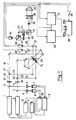
In Figur 1 sind mit (1) und (2) zwei zweimodige Laser bezeichnet, die weiter unten noch detaillierter beschrieben werden. Zur Stabilisierung beider Laser lenken die Strahlteiler (3, 4) einen Teilstrahl jedes Lasers auf ein Wollastonprisma (5, 6). Die Wollastonprismen trennen die beiden Modi jedes Laserstrahles entsprechend ihrer Polarisation auf. Die aufgespalteten Modi werden von Zwillingsphotodioden (7, 8) getrennt detektiert und zwei Regler (9, 10) gewinnen aus den Detektorsignalen zwei Regelsignale. Die Regler (9, 10) steuern über die Lasernetzteile (11, 12) den Entladungsstrom des jeweiligen Lasers so, daß beide Modi eines Lasers die gleiche Intensität besitzen. Dadurch werden beide Laser auf eine spektrale Unschärfe Δf/f = 3 x 10⁻⁸ stabilisiert. Dieses Stabilisierungsverfahren ist in der DE-C-20 43 734 detailliert beschrieben.In FIG. 1, (1) and (2) denote two two-mode lasers, which are described in more detail below. To stabilize both lasers, the beam splitters (3, 4) direct a partial beam of each laser onto a Wollaston prism (5, 6). The Wollaston prisms separate the two modes of each laser beam according to their polarization. The split modes are detected separately by twin photodiodes (7, 8) and two controllers (9, 10) obtain two control signals from the detector signals. The regulators (9, 10) control the discharge current of the respective laser via the laser power supplies (11, 12) so that both modes of a laser have the same intensity. As a result, both lasers are stabilized to a spectral blur Δf / f = 3 x 10⁻⁸. This stabilization process is described in detail in DE-C-20 43 734.
Durch den ersten Polarisator (13), der unter 45° zu den Polarisationsrichtungen der beiden Modi des ersten Lasers (1) steht, werden dessen beiden Modi interferenzfähig überlagert. Es entsteht eine amplitudenmodulierte Lichtwelle (15), deren Modulationsfrequenz Δf₁ durch den Frequenzabstand beider Modi gegeben ist.The first polarizer (13), which is at 45 ° to the polarization directions of the two modes of the first laser (1), overlaps its two modes in a manner capable of interference. The result is an amplitude-modulated light wave (15) whose
Durch den zweiten Polarisator (14) werden in gleicher Weise die beiden Modi des zweiten Lasers (2) interferenzfähig überlagert. Es entsteht eine zweite amplitudenmodulierte Lichtwelle (16), deren Modulationsfrequenz Δf₂ beträgt.The second polarizer (14) overlaps the two modes of the second laser (2) in a manner capable of interference in the same way. The result is a second amplitude-modulated light wave (16) whose modulation frequency is Δf₂.
Zwei Strahlteiler (17, 22) teilen die erste amplitudenmodulierte Welle (15) in zwei intensitätsgleiche Teilstrahlen (18, 19) und die zweite amplitudenmodulierte Welle (16) in zwei intensitätsgleiche Teilstrahlen (23, 24) auf. Ein Teilstrahl (19) des ersten Lasers und ein Teilstrahl (23) des zweiten Lasers schneiden sich in einem Punkt P₁, die beiden verbleibenden Teilstrahlen (18, 24) schneiden sich in einem zweiten Punkt P₂. Eine mechanische Zerhackeinrichtung (25) läßt abwechselnd Licht entweder durch den Punkt P₁ oder durch den Punkt P₂ transmittieren.Two beam splitters (17, 22) split the first amplitude-modulated wave (15) into two partial beams (18, 19) of equal intensity and the second amplitude-modulated wave (16) into two partial beams (23, 24) of equal intensity. A partial beam (19) of the first laser and a partial beam (23) of the second laser intersect in a point P₁, the two remaining partial beams (18, 24) intersect in a second point P₂. A mechanical chopping device (25) can alternately transmit light either through the point P₁ or through the point P₂.
Ein dritter Strahlteiler (27), der hinter der Zerhackeinrichtung (25) im Strahlengang angeordnet ist, überlagert den durch den Punkt P₁ gelenkten Teilstrahl (19) des ersten Lasers (1) und den durch der Punkt P₂ gelenkten Teilstrahl (24) des zweiten Lasers (2) und lenkt sie zum ersten Detektor (29), der als Photodiode ausgebildet ist.A third beam splitter (27), which is arranged behind the chopping device (25) in the beam path, overlays the partial beam (19) of the first laser (1) directed by the point P₁ and the partial beam (24) of the second laser directed by the point P₂ (2) and directs it to the first detector (29), which is designed as a photodiode.
Ein vierter Strahlteiler (26), der ebenfalls hinter der Zerhackeinrichtung (25) im Strahlengang angeordnet ist, überlagert die beiden anderen Teilstrahlen (18) und (23) und lenkt einen kleinen Lichtanteil zum zweiten,ebenfalls als Photodiode ausgebildeten Detektor (28). Der größte Lichtanteil bildet den Meßstrahl (30), der im weiteren Verlauf über ein Strahlteilerprisma (31) und über ein Teleskop (32) zum Meßobjekt (33) ausgesandt wird. Das Strahlteilerprisma (31) lenkt das an dem Meßobjekt (33) gestreute oder reflektierte Licht zum dritten als Photodiode ausgebildeten Detektor (34) um.A fourth beam splitter (26), which is also arranged behind the chopping device (25) in the beam path, superimposes the other two partial beams (18) and (23) and directs a small proportion of light to the second detector (28), which is also designed as a photodiode. The largest part of the light is formed by the measuring beam (30), which is then emitted to the measuring object (33) via a beam splitter prism (31) and a telescope (32). The beam splitter prism (31) deflects the light scattered or reflected on the measurement object (33) to the third detector (34) designed as a photodiode.
Damit keine Oberflächenreflexe des Teleskops (32) zum dritten Detektor (34) gelangen, ist das Strahlteilerprisma als polarisierender Strahlteiler ausgebildet. Hinter dem Teleskop (32) ist eine λ/4-Platte (35) angeordnet. Das am Meßobjekt (33) reflektierte oder gestreute Licht passiert die λ/4-Platte (35) zweifach und ist deshalb senkrecht zu den Oberflächenreflexen des Teleskops polarisiert.The beam splitter prism is designed as a polarizing beam splitter so that no surface reflections from the telescope (32) reach the third detector (34). A λ / 4 plate (35) is arranged behind the telescope (32). The light reflected or scattered on the measurement object (33) passes through the λ / 4 plate (35) twice and is therefore polarized perpendicular to the surface reflections of the telescope.
In der in Figur 1 dargestellten Situation läßt die mechanische Zerhackeinrichtung (25) Licht durch den Punkt P₁ transmittieren. In diesem Fall empfangen der zweite Detektor (28) und der dritte Detektor (34) Licht der Modulationsfrequenz Δf₂, während der erste Detektor (29) Licht der Modulationsfrequenz Δf₁ empfängt. Die Signale der erstgenannten Detektoren Photodioden (28, 34) sind in der Phase um einen Wert φ₁ gegeneinander verschoben.In the situation shown in Figure 1, the mechanical chopper (25) can transmit light through the point P₁. In this case, the second detector (28) and the third detector (34) receive light of the modulation frequency Δf₂, while the first detector (29) receives light of the modulation frequency Δf₁. The signals of the first-mentioned detectors photodiodes (28, 34) are shifted in phase by a value φ₁.
Zwei elektronische Mischer (36, 37) erzeugen aus den Signalen der drei Detektoren (28, 29, 34) zwei in der Phase um den Wert φ₁ verschobene elektronische Schwingungen der Differenzfrequenz Δf₁₂ = Δf₁ - Δf₂. Ein digitaler Phasenmesser (38) ermittelt den Wert φ₁ der Phasenverschiebung. Zur Erzeugung der Zählimpulse des digitalen Phasenmessers (38) ist das Signal des zweiten Detektors (28) herangezogen. Eine einzelne Phasenmessung erfolgt dann mit einer digitalen Genauigkeit von 2π Δf₁₂/Δf₂.Two electronic mixers (36, 37) generate from the signals of the three detectors (28, 29, 34) two electronic oscillations of the difference frequency Δf₁₂ = Δf₁ - Δf₂ shifted in phase by the value φ₁. A digital phase meter (38) determines the value φ₁ of the phase shift. The signal from the second detector (28) is used to generate the counting pulses of the digital phase meter (38). A single phase measurement is then carried out with a digital accuracy of 2π Δf₁₂ / Δf₂.
Während eines zweiten Meßschritts läßt die mechanische Zerhackeinrichtung (25) Licht durch den Punkt P₂ transmittieren. In diesem Fall empfangen der zweite Detektor (28) und der dritte Detektor (34) Licht der Modulationsfrequenz Δf₁, während der erste Detektor (29) Licht der Modulationsfrequenz Δf₂ empfangen. Die Signale der erstgenannten Detektoren (28, 34) sind nun in der Phase um einen Wert φ₂ gegeneinander verschoben. Der Wert φ₂ dieser Phasenverschiebung wird wie oben beschrieben ermittelt. Damit die digitale Genauigkeit konstant bleibt, ist nun zur Erzeugung der Zählimpulse des digitalen Phasenmessers (38) das Signal des ersten Detektors (29) herangezogen. Ein Schalter (39) schaltet den Trigger-Eingang des digitalen Phasenmessers mit der Frequenz der mechanischen Zerhackeinrichtung zwischen dem zweiten Detektor (28) und dem ersten Detektor (29) um.During a second measuring step, the mechanical chopping device (25) transmits light through the point P₂. In this case, the second detector (28) and the third detector (34) receive light of the modulation frequency Δf₁, while the first detector (29) receive light of the modulation frequency Δf₂. The signals of the first-mentioned detectors (28, 34) are now shifted in phase by a value φ₂. The value φ₂ this phase shift is determined as described above. So that the digital accuracy remains constant, the signal from the first detector (29) is now used to generate the counting pulses of the digital phase meter (38). A switch (39) switches the trigger input of the digital phase meter at the frequency of the mechanical chopper between the second detector (28) and the first detector (29).
Aus den gemessenen Phasenverschiebungen φ₁ und φ₂ wird der Entfernungswert s zwischen der Meßvorrichtung und dem Meßobjekt (33) berechnet. Dieser Entfernungswert ist eindeutig, solange s ≦ c/2 Δf₁₂ ist. Die digitale Genauigkeit Δs des Entfernungsmeßwertes ergibt sich zu![]()
![]()
Wie bereits weiter oben erwähnt, hängt die maximal erreichbare relative Meßgenauigkeit Δs/s von der spektralen Unschärfe Δf/f der Modulationsfrequenz ab. Die digitale Meßgenauigkeit Δs und der Eindeutigkeitsbereich sind dagegen durch die numerischen Werte Δf₁ und Δf₂ der Modenabstände der beiden Laser (1, 2) bestimmt.As already mentioned above, the maximum achievable relative measurement accuracy Δs / s depends on the spectral uncertainty Δf / f of the modulation frequency. The digital measuring accuracy Δs and the uniqueness range are determined by the numerical values Δf₁ and Δf₂ of the mode distances of the two lasers (1, 2).
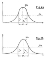
In der Figur 2a ist mit (20a) der spektrale Verlauf der Verstärkung des ersten Helium-Neon-Lasers gekennzeichnet. Die zwei benachbarten longitudinalen Modi n₁ und n₁+1 liegen oberhalb der Laserschwelle (21a) Der Frequenzabstand Δf₁ der beiden Modi ist durch die Resonatorlänge L₁ des ersten Lasers und die Lichtgeschwindigkeit c gegeben:![]()
![]()
Bei einer Resonatorlänge L₁ = 25 cm ergibt sich Δf₁ = 600 MHz. Es handelt sich um einen sogenannten "random"-polarisierten Laser, bei dem die benachbarten Modi n₁ und n₁+1 senkrecht zueinander linear polarisiert sind.With a resonator length L₁ = 25 cm there is Δf₁ = 600 MHz. It is a so-called "random" polarized laser, in which the
Das analoge gilt für den zweiten Helium-Neon-Laser, dessen spektraler Verlauf der Verstärkung mit (20b) in Figur 2b bezeichnet ist. Es handelt sich ebenfalls um einen zweimodigen, "random"-polarisierten Laser, dessen benachbarte longitudinale Modi n₂ und n₂+1 oberhalb der Laserschwelle (21b) liegen. Dieser zweite Laser hat jedoch eine um 0,21 mm geringere Resonatorlänge L₂ als der erste Laser. Deshalb ist auch der Frequenzabstand Δf₂ = c/2L₂ = 600,5 MHz. Der relative Unterschied der Resonatorlängen beider Laser beträgt etwa 1/1000. Ein entsprechendes Laserpaar kann z.B. aus einer Serienproduktion selektiert sein.The analog applies to the second helium-neon laser, the spectral course of the amplification being designated by (20b) in FIG. 2b. It is also a two-mode, "random" polarized laser, whose adjacent longitudinal modes n₂ and n₂ + 1 are above the laser threshold (21b). However, this second laser has a resonator length L₂ less than the first laser by 0.21 mm. Therefore, the frequency spacing Δf₂ = c / 2L₂ = 600.5 MHz. The relative difference in the resonator lengths of the two lasers is about 1/1000. A corresponding pair of lasers can e.g. selected from a series production.
Mit diesen beiden Lasern ergibt sich dann eine digitale Meßgenauigkeit Δs = ± 0,2 mm innerhalb eines Eindeutigkeitsbereiches von 300 m. Die Meßzeit einer Einzelmessung beträgt lediglich 2 »s.With these two lasers, a digital measuring accuracy Δs = ± 0.2 mm then results within a uniqueness range of 300 m. The measuring time of a single measurement is only 2 »s.
Zur weiteren Reduzierung des digitalen Fehlers können die Phasenverschiebungen über mehrere Perioden der Differenzfrequenz Δf₁₂ gemessen werden. Bei einer Messung über zehn Perioden der Differenzfrequenz Δf₁₂ beträgt der digitale Fehler nur noch 2π/12.010. Die Genauigkeit des Entfernungsmeßwertes beträgt dann Δs = ± 0,02 mm bei einer Meßzeit von 20 »s.To further reduce the digital error, the phase shifts can be measured over several periods of the difference frequency Δf₁₂. When measuring over ten periods of the difference frequency Δf₁₂ is the digital Error only 2π / 12.010. The accuracy of the distance measurement is then Δs = ± 0.02 mm with a measurement time of 20 »s.
Statistische Fehler lassen sich durch wiederholtes Messen der Werte φ₁ und φ₂ der Phasenverschiebung reduzieren. In diesem Fall kann in Figur 1 der digitale Phasenmesser (38) mit einer Umschaltung versehen sein, die die beiden Meßeingänge (38a, 38b) nach jedem Meßzyklus gegeneinander vertauscht. Dadurch wird der Einfluß systematischer Unterschiede zwischen den Spannungskomparatoren des digitalen Phasenmessers (38) unterdrückt.Statistical errors can be reduced by repeatedly measuring the values φ₁ and φ₂ of the phase shift. In this case, the digital phase meter (38) can be provided in FIG. 1 with a switchover, which interchanges the two measuring inputs (38a, 38b) after each measuring cycle. This suppresses the influence of systematic differences between the voltage comparators of the digital phase meter (38).
Gemäß Figur 1 ist zur Korrektur von Phasendriften zwischen dem zweiten Detektor (28) und dem dritten Detektor (34) im Strahlengang (30) des Meßlichts vor dem Strahlteilerprisma (31) ein weiterer Strahlteiler (40) vorgesehen, der einen Teilstrahl (43) des Meßlichts (30) zum dritten Detektor (34) umlenkt. Eine zweite mechanische Zerhackeinrichtung (41) unterbricht abwechselnd diesen Teilstrahl (43) und den Strahlengang (42) des am Meßobjekt (33) gestreuten oder reflektierten Lichts. In der Zeit, in der die mechanische Zerhackeinrichtung (41) den Teilstrahl (43) des Meßlichts (30) transmittieren läßt, wird ein Phasenkorrekturwert φk zwischen den Signalen des zweiten Detektors (28) und des dritten Detektors (34) gemessen. Dieser Phasenkorrekturwert φk wird von den Phasenwerten φ₁ oder φ₂ abgezogen.According to FIG. 1, a further beam splitter (40) is provided to correct phase drifts between the second detector (28) and the third detector (34) in the beam path (30) of the measuring light in front of the beam splitter prism (31) Measuring light (30) deflects to the third detector (34). A second mechanical chopping device (41) alternately interrupts this partial beam (43) and the beam path (42) of the light scattered or reflected on the measurement object (33). During the time in which the mechanical chopping device (41) transmits the partial beam (43) of the measuring light (30), a phase correction value φ k is measured between the signals of the second detector (28) and the third detector (34). This phase correction value φ k is subtracted from the phase values φ₁ or φ₂.
Soll die Entfernung zu einem streuenden Meßobjekt gemessen werden, so ist die polarisationsoptische Teilung des Meßlichts (30) und des am Meßobjekt (33) gestreuten oder reflektierten Lichts (42) nicht ideal, da eine Streuung stets depolarisierend wirkt. In diesem Fall ist eine geometrische Strahlteilung, die beispielsweise durch getrennte Sende- und Empfangsteleskope erfolgen kann, möglich.If the distance to a scattering measurement object is to be measured, the polarization-optical division of the measurement light (30) and the light (42) scattered or reflected on the measurement object (33) is not ideal, since scattering always has a depolarizing effect. In this case, a geometric beam splitting, which can be done, for example, by separate transmitting and receiving telescopes, is possible.
Die mechanischen Zerhackeinrichtungen (25, 41) können durch Flüssigkristallanordnungen oder auch durch elektro- oder meganeto-optische Schaltelemente ersetzt sein. Diese sind insbesondere dann vorzuziehen, wenn es auf kurze Meßzeiten und daher auf hohe Zerhackfrequenzen ankommt.The mechanical chopping devices (25, 41) can be replaced by liquid crystal arrangements or also by electro- or meganeto-optical switching elements. These are particularly preferable when short measurement times and therefore high chopping frequencies are important.
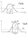
In einem zweiten Ausführungsbeispiel sind zwei unterschiedliche Laser eingesetzt. Der spektrale Verlauf des ersten Lasers ist in der Figur 3a mit (50a) gekennzeichnet. Das Maximum der Verstärkung liegt bei der Frequenz f₃. Es handelt sich wieder um einen Zweimoden-Laser. Die beiden Modi n₃ und n₃+1 liegen oberhalb der Laserschwelle (51a). Diese beiden Modi sind senkrecht zueinander linear polarisiert. Der Frequenzabstand zwischen den Modi ist mit Δf₃ bezeichnet. Die Frequenzstabilisierung dieses Lasers erfolgt entsprechend dem in Figur 1 beschriebenen Verfahren.In a second exemplary embodiment, two different lasers are used. The spectral profile of the first laser is identified by (50a) in FIG. 3a. The maximum gain is at the frequency f₃. It is again a two-mode laser. The two modes n₃ and n₃ + 1 are above the laser threshold (51a). These two modes are linearly polarized perpendicular to each other. The frequency difference between the modes is designated Δf₃. The frequency stabilization of this laser is carried out in accordance with the method described in FIG. 1.
Der zweite Laser ist gemäß Figur 3b dreimodig. Die drei Modi n₄-1, n₄ und n₄+1 liegen oberhalb der Laserschwelle (51b). Der Modus n₄ ist senkrecht zu den beiden anderen Modi linear polarisiert. Der Frequenzabstand der Modi Δf₄ ist kleiner als Δf₃/2. Der spektrale Verlauf der Verstärkung (50b) hat zwischen den Maxima (52b) und (53b) ein Minimum (54b), das Lamb-Dip genannt wird. Zur Stabilisierung teilt ein Polarisationsteiler den Laserstrahl entsprechend der Polarisation auf. Die beiden Modi n₄₋₁ und n₄₊₁ bilden den amplitudenmodulierten Meßstrahl mit der Modulationsfrequenz 2Δf₄. Die Intensität des Modus n₄ wird gemessen und zur Stabilisierung des Lasers herangezogen. Ein Regler stellt mittels Piezoelemente die Resonatorlänge so ein, daß die Frequenz des Modus n₄ mit der Frequenz des Lamb-Dips zusammenfällt. Die Intensität des Modus n₄ ist dann minimal.According to FIG. 3b, the second laser is three-mode. The three modes n₄-1, n₄ and n₄ + 1 lie above the laser threshold (51b). The mode n₄ is linearly polarized perpendicular to the other two modes. The frequency spacing of the modes Δf₄ is smaller than Δf₃ / 2. The spectral profile of the amplification (50b) has a minimum (54b) between the maxima (52b) and (53b), which is called the lamb dip. For stabilization, a polarization splitter splits the laser beam according to the polarization. The two modes n₄₋₁ and n₄₊₁ form the amplitude-modulated measuring beam with the modulation frequency 2Δf₄. The intensity of the mode n₄ is measured and used to stabilize the laser. A regulator adjusts the resonator length by means of piezo elements so that the frequency of mode n des coincides with the frequency of the lamb dip. The intensity of the mode n₄ is then minimal.
Der weitere Aufbau dieses zweiten Ausführungsbeispiels entspricht dem Ausführungsbeispiel nach Figur 1.The further structure of this second exemplary embodiment corresponds to the exemplary embodiment according to FIG. 1.
Claims (7)
- Optical distance-measuring apparatus comprising a light source for emitting a light beam to a measurement object and comprising an arrangement to determine the phase shift between light reflected specularly or diffusely by the measurement object and the emitted light, wherein the light source consists of two frequency-stabilized, multimode lasers (1, 2) with frequency spacings Δf₁ and Δf₂ between the modes, wherein the ratio Δf₁/Δf₂ of both frequency spacings differs from an integer number by an amount which is small compared to the number one, wherein several modes of each laser are superimposed in an interfering manner for generating two amplitude-modulated beams (15, 16) and wherein detectors (28, 29) for detecting partial beams of both amplitude-modulated beams (15, 16) and a further detector (34) for detecting light reflected specularly or diffusely at the measurement object (33) are provided, characterized in that the arrangement to determine the phase shift (36, 37, 38) electronically mixes the output signal of the detector (34) detecting light reflected specularly or diffusely at the measurement object (33) and the output signal of the detector (29) detecting light of the respective different amplitude-modulated beam (15, 16).
- Optical distance-measuring apparatus of claim 1, characterized in that each of the two lasers (1, 2) has two modes.
- Optical distance-measuring apparatus of claim 2, characterized in that the ratio Δf₁/Δf₂ of the frequency spacings of the two lasers differs from the number one by less than 1 %.
- Optical distance-measuring apparatus of one of the claims 1-3, characterized in that an arrangement (25) for interchanging the two laser beams is provided in a manner that the amplitude-modulated beams (15, 16) of the first laser (1) and of the second laser (2) are emitted alternately to the measurement object (33).
- Optical distance-measuring apparatus of claim 4, characterized in that the arrangement for the mutual interchange of both laser beams is a mechanical chopper (25) which allows light to transmit alternately at two different points (P₁, P₂).
- Optical distance-measuring apparatus of claim 4 or 5, characterized in that for the compensation of phase drifts between the two detectors (28, 34) receiving light of the same laser, a second mechanical chopper (41) is provided which allows the transmission of light to the third detector (34) alternately of light (42) reflected diffusely or specularly at the measurement object (33) and a part of the light (43) to be emitted.
- Optical distance-measuring apparatus of one of the claims 1 to 6, characterized in that for determining the phase shift between the light (42) reflected diffusely or specularly at the measurement object (33) and the emitted light (30), a digital phasemeter (38) is provided, the clocking frequency of which is given by the frequency spacing of two modes of one of the two lasers (1, 2).
Applications Claiming Priority (2)
| Application Number | Priority Date | Filing Date | Title |
|---|---|---|---|
| DE3937268 | 1989-11-09 | ||
| DE3937268A DE3937268A1 (en) | 1989-11-09 | 1989-11-09 | OPTICAL DISTANCE MEASURING DEVICE |
Publications (3)
| Publication Number | Publication Date |
|---|---|
| EP0428027A2 EP0428027A2 (en) | 1991-05-22 |
| EP0428027A3 EP0428027A3 (en) | 1992-05-20 |
| EP0428027B1 true EP0428027B1 (en) | 1995-08-09 |
Family
ID=6393162
Family Applications (1)
| Application Number | Title | Priority Date | Filing Date |
|---|---|---|---|
| EP90121050A Expired - Lifetime EP0428027B1 (en) | 1989-11-09 | 1990-11-02 | Optical distance measurement device |
Country Status (4)
| Country | Link |
|---|---|
| US (1) | US5054912A (en) |
| EP (1) | EP0428027B1 (en) |
| JP (1) | JPH03170895A (en) |
| DE (2) | DE3937268A1 (en) |
Cited By (1)
| Publication number | Priority date | Publication date | Assignee | Title |
|---|---|---|---|---|
| US6411371B1 (en) | 1998-09-02 | 2002-06-25 | Leica Geosystems Ag | Device for optical distance measurement |
Families Citing this family (22)
| Publication number | Priority date | Publication date | Assignee | Title |
|---|---|---|---|---|
| US5274361A (en) * | 1991-08-15 | 1993-12-28 | The United States Of America As Represented By The Secretary Of The Navy | Laser optical mouse |
| US5371587A (en) * | 1992-05-06 | 1994-12-06 | The Boeing Company | Chirped synthetic wavelength laser radar |
| FR2706602B1 (en) * | 1993-06-10 | 1995-09-01 | Bertin & Cie | Rangefinder. |
| GB2285550B (en) * | 1994-01-05 | 1997-09-17 | Creo Products Inc | Optical coordinate measuring system for large objects |
| US5793483A (en) * | 1996-02-07 | 1998-08-11 | Visidyne, Inc. | Optical measurement system |
| US5883706A (en) * | 1996-12-05 | 1999-03-16 | Northrop Grumman Corporation | Multiplexer for laser ranging devices and the like |
| US6483593B1 (en) | 1999-08-10 | 2002-11-19 | The Boeing Company | Hetrodyne interferometer and associated interferometric method |
| WO2001076692A1 (en) | 2000-04-11 | 2001-10-18 | Oncology Automation, Inc. | Positioning systems and related methods |
| US6646723B1 (en) * | 2002-05-07 | 2003-11-11 | The United States Of America As Represented By The Administrator Of The National Aeronautics And Space Administration | High precision laser range sensor |
| KR100468155B1 (en) * | 2002-06-27 | 2005-01-26 | 한국과학기술원 | Heterodyne laser interferometer using heteromodal helium-neon laser and super heterodyne phase measurement |
| US7196789B2 (en) * | 2003-10-15 | 2007-03-27 | Polychromix Corporation | Light processor providing wavelength control and method for same |
| DE10352402B4 (en) * | 2003-11-10 | 2015-12-17 | Lasertec Gmbh | Laser processing machine and laser processing method |
| US7215413B2 (en) * | 2005-06-24 | 2007-05-08 | The Boeing Company | Chirped synthetic wave laser radar apparatus and methods |
| DE102009012646A1 (en) * | 2009-03-11 | 2010-09-23 | Amt Gmbh | distance measurement |
| JP2014232005A (en) * | 2013-05-28 | 2014-12-11 | 富士ゼロックス株式会社 | Measurement device |
| US9488722B2 (en) * | 2013-06-05 | 2016-11-08 | Samsung Electronics Co., Ltd. | Time-of-flight ranging system and method with extended range |
| US10223793B1 (en) | 2015-08-05 | 2019-03-05 | Al Incorporated | Laser distance measuring method and system |
| US11069082B1 (en) | 2015-08-23 | 2021-07-20 | AI Incorporated | Remote distance estimation system and method |
| US11935256B1 (en) | 2015-08-23 | 2024-03-19 | AI Incorporated | Remote distance estimation system and method |
| US9972098B1 (en) | 2015-08-23 | 2018-05-15 | AI Incorporated | Remote distance estimation system and method |
| US10408604B1 (en) | 2015-09-07 | 2019-09-10 | AI Incorporated | Remote distance estimation system and method |
| US10346995B1 (en) | 2016-08-22 | 2019-07-09 | AI Incorporated | Remote distance estimation system and method |
Family Cites Families (6)
| Publication number | Priority date | Publication date | Assignee | Title |
|---|---|---|---|---|
| US3619057A (en) * | 1967-06-28 | 1971-11-09 | North American Aviation Inc | Geodetic laser survey system |
| GB1593733A (en) * | 1976-12-24 | 1981-07-22 | Marconi Co Ltd | Distance measuring instruments |
| US4163954A (en) * | 1977-03-11 | 1979-08-07 | Rockwell International Corporation | High energy coherent pulse source for laser system |
| US4666295A (en) * | 1983-03-17 | 1987-05-19 | Hughes Aircraft Company | Linear FM chirp laser |
| US4744653A (en) * | 1984-04-12 | 1988-05-17 | Matsushita Electric Industrial Co., Ltd. | Distance measurement by laser light |
| CH678108A5 (en) * | 1987-04-28 | 1991-07-31 | Wild Leitz Ag |
-
1989
- 1989-11-09 DE DE3937268A patent/DE3937268A1/en not_active Withdrawn
-
1990
- 1990-11-02 DE DE59009499T patent/DE59009499D1/en not_active Expired - Fee Related
- 1990-11-02 EP EP90121050A patent/EP0428027B1/en not_active Expired - Lifetime
- 1990-11-06 US US07/609,584 patent/US5054912A/en not_active Expired - Fee Related
- 1990-11-09 JP JP2302806A patent/JPH03170895A/en active Pending
Cited By (2)
| Publication number | Priority date | Publication date | Assignee | Title |
|---|---|---|---|---|
| US6411371B1 (en) | 1998-09-02 | 2002-06-25 | Leica Geosystems Ag | Device for optical distance measurement |
| DE19840049C5 (en) * | 1998-09-02 | 2007-11-08 | Leica Geosystems Ag | Device for optical distance measurement |
Also Published As
| Publication number | Publication date |
|---|---|
| EP0428027A2 (en) | 1991-05-22 |
| EP0428027A3 (en) | 1992-05-20 |
| DE3937268A1 (en) | 1991-05-16 |
| JPH03170895A (en) | 1991-07-24 |
| DE59009499D1 (en) | 1995-09-14 |
| US5054912A (en) | 1991-10-08 |
Similar Documents
| Publication | Publication Date | Title |
|---|---|---|
| EP0428027B1 (en) | Optical distance measurement device | |
| DE3687175T2 (en) | HETERODYNES INTERFEROMETER SYSTEM. | |
| DE3306709C2 (en) | ||
| DE602005001664T2 (en) | Optical rangefinder | |
| DE2235318C3 (en) | Method for opto-electronic measurement of distance and height difference and arrangement for carrying out the method | |
| DE3608075C2 (en) | ||
| EP1851504B1 (en) | Phase noise compensation for an interferometer measuring absolute distance | |
| DE2949327C2 (en) | Optical device for determining a rotation | |
| DE19811550C2 (en) | Method and circuit arrangement for generating frequency signals | |
| DE19743493C2 (en) | Method and device for laser frequency measurement and stabilization | |
| DE69912969T2 (en) | OPTICAL PHASE DETECTOR | |
| DE69127038T2 (en) | Distance measuring device | |
| EP0623802A2 (en) | Procedure and device for absolute measurements with a laser-interferometer | |
| DE69807683T2 (en) | ELLIPSOMETER WITH TWO LASERS | |
| EP0172390A2 (en) | Method and apparatus for rotation rate measurement using a passive optical resonator | |
| EP0074609B1 (en) | Apparatus for measuring rotational speed | |
| DE69216464T2 (en) | Apparatus for measuring the wavelength variation | |
| DE1253468B (en) | Device for determining the distance to a reflector | |
| EP0670469A1 (en) | Brillouin-ring laser gyro | |
| AT399222B (en) | INTERFEROMETRIC DEVICE FOR MEASURING THE POSITION OF A REFLECTIVE OBJECT | |
| EP0205406B1 (en) | Electro-optical range finder | |
| EP1594020A1 (en) | Method for generating an offset-free optical frequency comb and laser apparatus therefor | |
| DE3528259A1 (en) | Method and device for interferometric length measurement using semiconductor lasers as light source | |
| DE69000564T2 (en) | OPTICAL SYSTEM FOR MEASURING LINEAR OR ANGLE CHANGES. | |
| EP0646766A2 (en) | Procedure and device for absolute interferometry with a laser-diode beam |
Legal Events
| Date | Code | Title | Description |
|---|---|---|---|
| PUAI | Public reference made under article 153(3) epc to a published international application that has entered the european phase |
Free format text: ORIGINAL CODE: 0009012 |
|
| AK | Designated contracting states |
Kind code of ref document: A2 Designated state(s): CH DE FR GB LI NL SE |
|
| PUAL | Search report despatched |
Free format text: ORIGINAL CODE: 0009013 |
|
| AK | Designated contracting states |
Kind code of ref document: A3 Designated state(s): CH DE FR GB LI NL SE |
|
| 17P | Request for examination filed |
Effective date: 19921113 |
|
| 17Q | First examination report despatched |
Effective date: 19940216 |
|
| GRAA | (expected) grant |
Free format text: ORIGINAL CODE: 0009210 |
|
| AK | Designated contracting states |
Kind code of ref document: B1 Designated state(s): CH DE FR GB LI NL SE |
|
| PG25 | Lapsed in a contracting state [announced via postgrant information from national office to epo] |
Ref country code: NL Free format text: LAPSE BECAUSE OF NON-PAYMENT OF DUE FEES Effective date: 19950809 Ref country code: FR Free format text: THE PATENT HAS BEEN ANNULLED BY A DECISION OF A NATIONAL AUTHORITY Effective date: 19950809 |
|
| REF | Corresponds to: |
Ref document number: 59009499 Country of ref document: DE Date of ref document: 19950914 |
|
| PG25 | Lapsed in a contracting state [announced via postgrant information from national office to epo] |
Ref country code: SE Effective date: 19951109 |
|
| GBT | Gb: translation of ep patent filed (gb section 77(6)(a)/1977) |
Effective date: 19951102 |
|
| NLV1 | Nl: lapsed or annulled due to failure to fulfill the requirements of art. 29p and 29m of the patents act | ||
| EN | Fr: translation not filed | ||
| PLBE | No opposition filed within time limit |
Free format text: ORIGINAL CODE: 0009261 |
|
| STAA | Information on the status of an ep patent application or granted ep patent |
Free format text: STATUS: NO OPPOSITION FILED WITHIN TIME LIMIT |
|
| 26N | No opposition filed | ||
| PGFP | Annual fee paid to national office [announced via postgrant information from national office to epo] |
Ref country code: GB Payment date: 19981012 Year of fee payment: 9 |
|
| PGFP | Annual fee paid to national office [announced via postgrant information from national office to epo] |
Ref country code: DE Payment date: 19981022 Year of fee payment: 9 |
|
| PGFP | Annual fee paid to national office [announced via postgrant information from national office to epo] |
Ref country code: CH Payment date: 19981023 Year of fee payment: 9 |
|
| PG25 | Lapsed in a contracting state [announced via postgrant information from national office to epo] |
Ref country code: GB Free format text: LAPSE BECAUSE OF NON-PAYMENT OF DUE FEES Effective date: 19991102 |
|
| PG25 | Lapsed in a contracting state [announced via postgrant information from national office to epo] |
Ref country code: LI Free format text: LAPSE BECAUSE OF NON-PAYMENT OF DUE FEES Effective date: 19991130 Ref country code: CH Free format text: LAPSE BECAUSE OF NON-PAYMENT OF DUE FEES Effective date: 19991130 |
|
| GBPC | Gb: european patent ceased through non-payment of renewal fee |
Effective date: 19991102 |
|
| REG | Reference to a national code |
Ref country code: CH Ref legal event code: PL |
|
| PG25 | Lapsed in a contracting state [announced via postgrant information from national office to epo] |
Ref country code: DE Free format text: LAPSE BECAUSE OF NON-PAYMENT OF DUE FEES Effective date: 20000901 |