EP0427481A2 - Bilderzeugungsvorrichtung - Google Patents
Bilderzeugungsvorrichtung Download PDFInfo
- Publication number
- EP0427481A2 EP0427481A2 EP90312054A EP90312054A EP0427481A2 EP 0427481 A2 EP0427481 A2 EP 0427481A2 EP 90312054 A EP90312054 A EP 90312054A EP 90312054 A EP90312054 A EP 90312054A EP 0427481 A2 EP0427481 A2 EP 0427481A2
- Authority
- EP
- European Patent Office
- Prior art keywords
- imager
- cell
- image tube
- cells
- tube
- Prior art date
- Legal status (The legal status is an assumption and is not a legal conclusion. Google has not performed a legal analysis and makes no representation as to the accuracy of the status listed.)
- Withdrawn
Links
Images


Classifications
-
- H—ELECTRICITY
- H01—ELECTRIC ELEMENTS
- H01M—PROCESSES OR MEANS, e.g. BATTERIES, FOR THE DIRECT CONVERSION OF CHEMICAL ENERGY INTO ELECTRICAL ENERGY
- H01M50/00—Constructional details or processes of manufacture of the non-active parts of electrochemical cells other than fuel cells, e.g. hybrid cells
- H01M50/20—Mountings; Secondary casings or frames; Racks, modules or packs; Suspension devices; Shock absorbers; Transport or carrying devices; Holders
- H01M50/204—Racks, modules or packs for multiple batteries or multiple cells
-
- H—ELECTRICITY
- H01—ELECTRIC ELEMENTS
- H01M—PROCESSES OR MEANS, e.g. BATTERIES, FOR THE DIRECT CONVERSION OF CHEMICAL ENERGY INTO ELECTRICAL ENERGY
- H01M50/00—Constructional details or processes of manufacture of the non-active parts of electrochemical cells other than fuel cells, e.g. hybrid cells
- H01M50/20—Mountings; Secondary casings or frames; Racks, modules or packs; Suspension devices; Shock absorbers; Transport or carrying devices; Holders
- H01M50/247—Mountings; Secondary casings or frames; Racks, modules or packs; Suspension devices; Shock absorbers; Transport or carrying devices; Holders specially adapted for portable devices, e.g. mobile phones, computers, hand tools or pacemakers
-
- H—ELECTRICITY
- H04—ELECTRIC COMMUNICATION TECHNIQUE
- H04N—PICTORIAL COMMUNICATION, e.g. TELEVISION
- H04N23/00—Cameras or camera modules comprising electronic image sensors; Control thereof
- H04N23/50—Constructional details
-
- Y—GENERAL TAGGING OF NEW TECHNOLOGICAL DEVELOPMENTS; GENERAL TAGGING OF CROSS-SECTIONAL TECHNOLOGIES SPANNING OVER SEVERAL SECTIONS OF THE IPC; TECHNICAL SUBJECTS COVERED BY FORMER USPC CROSS-REFERENCE ART COLLECTIONS [XRACs] AND DIGESTS
- Y02—TECHNOLOGIES OR APPLICATIONS FOR MITIGATION OR ADAPTATION AGAINST CLIMATE CHANGE
- Y02E—REDUCTION OF GREENHOUSE GAS [GHG] EMISSIONS, RELATED TO ENERGY GENERATION, TRANSMISSION OR DISTRIBUTION
- Y02E60/00—Enabling technologies; Technologies with a potential or indirect contribution to GHG emissions mitigation
- Y02E60/10—Energy storage using batteries
Definitions
- This invention relates to an imager, and more particularly, but not exclusively to an imager used for amplifying radiation received from a viewed scene in low light level conditions.
- imagers are self contained units, not requiring an external power supply, and are of a compact lightweight design.
- an imager comprising: an image tube arranged to receive radiation from a scene; a plurality of electrical cells for providing a power supply to the tube; and an aperture for viewing an output from the image tube, wherein the viewing aperture and output of the image tube define an optical axis about which the cells are arranged in a plane substantially perpendicular to the axis.
- an imager comprising: an image tube arranged to receive radiation from a scene; an electrical cell with an aperture therein for providing a power supply to the tube; and an output for viewing an output from the image tube, wherein the viewing aperture output of the image tube define an optical axis passing through the aperture in the cell.
- An imager in accordance with the invention may be made particularly compact as the cell, or cells, can be positioned relatively close about the optical axis the only requirement being that there is sufficient area about the optical axis to enable output radiation from the image tube to pass unimpeded to the viewing aperture. As this area may be arranged to be relatively small compared to the diameter of the image tube, the diameter of the imager as a whole need not be governed by the power supply as in previous arrangements.
- the imager includes a substantially cylindrical housing within which the cell or cells are located.
- This shape is particularly easy to handle and store, and is not prone to damage having no protrusions.
- the imager comprises two sections, a first section housing an objective lens and the image tube, and the second section housing the aperture and the cell or cells.
- the two sections may be relatively rotatable, the relative position of the two sections controlling the power supply to the tube thereby eliminating the need for an external switch.
- the cells are separately connectable to the image tube, the imager including a plurality of contact regions, each region being associated with a respective different cell and forming part of the electrical path from the cell to the image tube. This enables each cell to be used in turn as the previous cell is exhausted, simply by rotating the first section relative to the second.
- the imager comprises a momentary switch for activating the image tube, so that the tube is only operative while the switch is held in position.
- a momentary switch for activating the image tube, so that the tube is only operative while the switch is held in position.
- an imager 1 for amplifying received light from a scene includes an image tube 2 located in a substantially cylindrical housing comprising two sections 3a and 3b.
- the first section 3a, which contains the image tube 2 also comprises an objective lens arrangement 4 for focusing received light on a sensor array 5 of the image tube 2, and electrical contacts 6 and 7 connected to the image tube 2.
- the second section 3b of the cylindrical housing 3 is illustrated separate from the first section 3a in figure 1B, and in plan viewing in figure 1C.
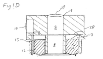
- This second section 3b comprises a viewing aperture 9, eyepiece lens 10 and three cell compartments 11a, 11b and 11c in which cells 12, (only one of which is shown), are inserted.
- the negative terminal of each cell is connected by conductor 13 to a momentary switch 14 mounted on the side of the section of the cylinder 3b. Pressure applied to the switch 14 activates the switch, for the duration for which the switch is depressed, such that it electrically connects the conductor 13 with contact pin 15.
- FIG. 1D an alternative arrangement of section 3B is illustrated, wherein a single toroidal cell has been substituted for the previous three cell arrangement of Figure 1B.
- the assembled sections 3a and 3b and associated components of the imager 1 define a central volume 8 through which the output of the image tube is transmitted to the eyepiece lens 10.
- the optical axis being collinear with the longitudinal axis of the imager 1.
- Figure 2 depicts an imager for amplifying received light from a scene and includes an image tube 31 contained within a generally cylindrical housing 32.
- the housing 32 comprises first and second relatively rotatable sections 33 and 34 respectively having a rotating joint between them.
- An eyepiece lens arrangement, through which an operator looks, is located in the first section 33.
- the image tube 31 and a front end lens arrangement 37 at which radiation from the viewed scene is received are housed within the second section 34.
- the power supply for the image tube 31 consists of three lithium cells 38, 39 and 40 of the type designated DL13N, however it will be realised that many cell types are available which would be equally suited to this application.
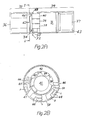
- the cells 38, 39 and 40 are contained within the second section 34 and are disposed around the periphery of the apparatus, as can be more clearly seen in Figure 28, the central region 41 being the viewing area through which the imaged scene is transmitted.
- a contact pad 42 is located within the first section 33 and is arranged to move with it such that, when the relative position of the first and second sections is changed, the contact pad 42 is moved with respect to the cells 38, 39 and 40, thus controlling the power supply to the image tube 31.
- An LED 43 is also included within the apparatus, being located at the front surface of the device so that, when it is switched on, it illuminates the viewed scene with infra-red radiation.
- the cells 38, 39 and 40 and the contact pad 42 are arranged so that one cell at a time is used to power the image tube 31.
- the contact pad 42 is a semi-annular plate having contact portions 44, 45 and 46 at its ends.
- One of the contact portions 16 extends entirely across the end of the contact plate 42 and is bent towards the cells 38, 39 and 40 such that when it is positioned adjacent to a cell it makes an electrical connection therewith.
- the other end of the contact pad 42 is split into two contact portions 44 and 45.
- Contact regions 47, 48 and 49 are laid down on a board 50 located in the second section 34, each including two parts A and B. The larger part A is connected to the image tube 31 and the smaller part B provides an electrical path to the LED 43.
- the two contact portions 44 and 45 of the contact pad 42 are arranged to make contact with a region when immediately adjacent to it and thus provide a conductive path from a cell to the image tube 31 and/or LED 43.
- the first cell 38 is connected via contact portion 46 and the contact pad 42 to the contact region 47.
- Both contact portions 44 and 45 connect with the larger part of the region A and therefore the image tube is switched on but the LED is off. If the contact pad is rotated anti-clockwise with respect to the second section 34 the contact portions 44 and 45 come into contact with portions B and A respectively of the first contact region 47, thus energising the LED as well as providing power to the image tube 31.
- the cell 38 is switched out of use and the second cell 39 is switched on. Again, this may be used to power the image tube 31 alone or to provide power to the LED as well.
- a spring and ball locator 51 is included to give a positive indication at each available position, including the off position.
- the front end lens arrangement 37 includes a threaded portion on its outer surface which engages with the housing 32, enabling it to be readily removed for either replacement with another arrangement or for access to the image tube 31 or to the cells 38, 39 and 40.
- the apparatus may also include an aperture control so as to give optimum performance of the image tube 31 under a variety of operating conditions.
Landscapes
- Engineering & Computer Science (AREA)
- Chemical & Material Sciences (AREA)
- Chemical Kinetics & Catalysis (AREA)
- Electrochemistry (AREA)
- General Chemical & Material Sciences (AREA)
- Multimedia (AREA)
- Signal Processing (AREA)
- Life Sciences & Earth Sciences (AREA)
- Biophysics (AREA)
- Computer Hardware Design (AREA)
- Studio Devices (AREA)
- Endoscopes (AREA)
Applications Claiming Priority (2)
| Application Number | Priority Date | Filing Date | Title |
|---|---|---|---|
| GB8925059 | 1989-11-07 | ||
| GB898925059A GB8925059D0 (en) | 1989-11-07 | 1989-11-07 | Image tube apparatus |
Publications (2)
| Publication Number | Publication Date |
|---|---|
| EP0427481A2 true EP0427481A2 (de) | 1991-05-15 |
| EP0427481A3 EP0427481A3 (en) | 1992-10-28 |
Family
ID=10665833
Family Applications (1)
| Application Number | Title | Priority Date | Filing Date |
|---|---|---|---|
| EP19900312054 Withdrawn EP0427481A3 (en) | 1989-11-07 | 1990-11-02 | An imager |
Country Status (3)
| Country | Link |
|---|---|
| EP (1) | EP0427481A3 (de) |
| GB (2) | GB8925059D0 (de) |
| NO (1) | NO904790D0 (de) |
Cited By (1)
| Publication number | Priority date | Publication date | Assignee | Title |
|---|---|---|---|---|
| WO2007127645A1 (en) * | 2006-04-24 | 2007-11-08 | Medtronic, Inc. | Torroidal battery for use in implantable medical device |
Families Citing this family (1)
| Publication number | Priority date | Publication date | Assignee | Title |
|---|---|---|---|---|
| US10007171B1 (en) | 2015-10-21 | 2018-06-26 | Google Llc | Battery with a structural gap |
Family Cites Families (5)
| Publication number | Priority date | Publication date | Assignee | Title |
|---|---|---|---|---|
| JPS5048287U (de) * | 1973-08-28 | 1975-05-13 | ||
| GB1503224A (en) * | 1975-08-09 | 1978-03-08 | Elliott Bros | Television cameras |
| US4440476A (en) * | 1982-05-12 | 1984-04-03 | Jacobson Andrew G | Optical device for an intensifier tube |
| FR2575280B1 (fr) * | 1984-12-21 | 1987-01-23 | Trt Telecom Radio Electr | Lunette de tir jour/nuit pour arme legere |
| DE3809406A1 (de) * | 1988-03-21 | 1989-10-05 | Geraetebau Gmbh | Batteriepack |
-
1989
- 1989-11-07 GB GB898925059A patent/GB8925059D0/en active Pending
-
1990
- 1990-11-02 GB GB9023876A patent/GB2237960A/en not_active Withdrawn
- 1990-11-02 EP EP19900312054 patent/EP0427481A3/en not_active Withdrawn
- 1990-11-05 NO NO904790A patent/NO904790D0/no unknown
Cited By (1)
| Publication number | Priority date | Publication date | Assignee | Title |
|---|---|---|---|---|
| WO2007127645A1 (en) * | 2006-04-24 | 2007-11-08 | Medtronic, Inc. | Torroidal battery for use in implantable medical device |
Also Published As
| Publication number | Publication date |
|---|---|
| GB8925059D0 (en) | 1989-12-28 |
| EP0427481A3 (en) | 1992-10-28 |
| GB2237960A (en) | 1991-05-15 |
| GB9023876D0 (en) | 1990-12-12 |
| NO904790D0 (no) | 1990-11-05 |
Similar Documents
| Publication | Publication Date | Title |
|---|---|---|
| US5347123A (en) | Optical control switch device having a plurality of light receptors | |
| US5239983A (en) | Connector apparatus for endoscope | |
| US4448509A (en) | Interchangeable lens barrel with signal transfer contacts | |
| US7662093B2 (en) | Reduced size imaging device | |
| US5408359A (en) | Visual security eyecup | |
| EP1836945A2 (de) | Schaltmechanismus zur Verwendung bei medizinischen Geräten und Bildaufnahmevorrichtung zur Verwendung bei Endoskopen | |
| JPS641004B2 (de) | ||
| US5056886A (en) | Optical switching device | |
| US4580198A (en) | Illuminator for medical examination telescope | |
| EP1273990A2 (de) | Betätigungshebelvorrichtung | |
| US4748319A (en) | Bar code scanner | |
| US5515201A (en) | Microscope-telescope combination fitted with illuminating apparatus | |
| US5030982A (en) | Single lens reflex camera | |
| ATE324687T1 (de) | Verbinder mit kugelmatrixgehäuse | |
| GB2230102A (en) | Camera with a strobe on a rotatable arm | |
| EP0427481A2 (de) | Bilderzeugungsvorrichtung | |
| US4443085A (en) | Camera with an interchangeable lens | |
| JPS59152424A (ja) | カメラと附属品間の電気信号を授受する電気信号授受装置 | |
| US5852697A (en) | Combination light source and connector | |
| GB2052025A (en) | Laser Sight for Firearms | |
| US5328391A (en) | Contact pin subassembly | |
| US6257741B1 (en) | Lamp assembly for a light source | |
| GB2100462A (en) | Automatically focussing binoculars | |
| JP2691922B2 (ja) | 位置検出装置 | |
| JPS5850335Y2 (ja) | 交換レンズ用コネクタ− |
Legal Events
| Date | Code | Title | Description |
|---|---|---|---|
| PUAI | Public reference made under article 153(3) epc to a published international application that has entered the european phase |
Free format text: ORIGINAL CODE: 0009012 |
|
| AK | Designated contracting states |
Kind code of ref document: A2 Designated state(s): AT BE CH DE DK ES FR GR IT LI NL SE |
|
| PUAL | Search report despatched |
Free format text: ORIGINAL CODE: 0009013 |
|
| AK | Designated contracting states |
Kind code of ref document: A3 Designated state(s): AT BE CH DE DK ES FR GR IT LI NL SE |
|
| STAA | Information on the status of an ep patent application or granted ep patent |
Free format text: STATUS: THE APPLICATION IS DEEMED TO BE WITHDRAWN |
|
| 18D | Application deemed to be withdrawn |
Effective date: 19921201 |