EP0427177A2 - Vibrator - Google Patents
Vibrator Download PDFInfo
- Publication number
- EP0427177A2 EP0427177A2 EP90121146A EP90121146A EP0427177A2 EP 0427177 A2 EP0427177 A2 EP 0427177A2 EP 90121146 A EP90121146 A EP 90121146A EP 90121146 A EP90121146 A EP 90121146A EP 0427177 A2 EP0427177 A2 EP 0427177A2
- Authority
- EP
- European Patent Office
- Prior art keywords
- vibrating body
- vibrator
- electrodes
- vibrating
- electrode
- Prior art date
- Legal status (The legal status is an assumption and is not a legal conclusion. Google has not performed a legal analysis and makes no representation as to the accuracy of the status listed.)
- Granted
Links
- 239000000463 material Substances 0.000 claims abstract description 8
- 230000002093 peripheral effect Effects 0.000 claims description 17
- 230000010355 oscillation Effects 0.000 description 11
- 238000010586 diagram Methods 0.000 description 10
- 238000001514 detection method Methods 0.000 description 7
- 238000004519 manufacturing process Methods 0.000 description 7
- 230000010287 polarization Effects 0.000 description 6
- 238000004544 sputter deposition Methods 0.000 description 6
- BQCADISMDOOEFD-UHFFFAOYSA-N Silver Chemical compound [Ag] BQCADISMDOOEFD-UHFFFAOYSA-N 0.000 description 5
- 229910052709 silver Inorganic materials 0.000 description 5
- 239000004332 silver Substances 0.000 description 5
- 239000007769 metal material Substances 0.000 description 4
- 230000035945 sensitivity Effects 0.000 description 4
- 230000001360 synchronised effect Effects 0.000 description 4
- 238000001771 vacuum deposition Methods 0.000 description 4
- 238000005452 bending Methods 0.000 description 3
- 239000000919 ceramic Substances 0.000 description 3
- 230000005684 electric field Effects 0.000 description 3
- 238000000034 method Methods 0.000 description 3
- 238000007747 plating Methods 0.000 description 3
- 238000005245 sintering Methods 0.000 description 3
- PXHVJJICTQNCMI-UHFFFAOYSA-N Nickel Chemical compound [Ni] PXHVJJICTQNCMI-UHFFFAOYSA-N 0.000 description 2
- 206010044565 Tremor Diseases 0.000 description 2
- 239000013078 crystal Substances 0.000 description 2
- 239000002305 electric material Substances 0.000 description 2
- 238000003754 machining Methods 0.000 description 2
- 229910052751 metal Inorganic materials 0.000 description 2
- 239000002184 metal Substances 0.000 description 2
- 238000007738 vacuum evaporation Methods 0.000 description 2
- WSMQKESQZFQMFW-UHFFFAOYSA-N 5-methyl-pyrazole-3-carboxylic acid Chemical compound CC1=CC(C(O)=O)=NN1 WSMQKESQZFQMFW-UHFFFAOYSA-N 0.000 description 1
- RYGMFSIKBFXOCR-UHFFFAOYSA-N Copper Chemical compound [Cu] RYGMFSIKBFXOCR-UHFFFAOYSA-N 0.000 description 1
- 229910000942 Elinvar Inorganic materials 0.000 description 1
- 229910052782 aluminium Inorganic materials 0.000 description 1
- XAGFODPZIPBFFR-UHFFFAOYSA-N aluminium Chemical compound [Al] XAGFODPZIPBFFR-UHFFFAOYSA-N 0.000 description 1
- 229910052802 copper Inorganic materials 0.000 description 1
- 239000010949 copper Substances 0.000 description 1
- 239000007772 electrode material Substances 0.000 description 1
- 230000005284 excitation Effects 0.000 description 1
- PCHJSUWPFVWCPO-UHFFFAOYSA-N gold Chemical compound [Au] PCHJSUWPFVWCPO-UHFFFAOYSA-N 0.000 description 1
- 229910052737 gold Inorganic materials 0.000 description 1
- 239000010931 gold Substances 0.000 description 1
- 229910052759 nickel Inorganic materials 0.000 description 1
Images


Classifications
-
- G—PHYSICS
- G01—MEASURING; TESTING
- G01C—MEASURING DISTANCES, LEVELS OR BEARINGS; SURVEYING; NAVIGATION; GYROSCOPIC INSTRUMENTS; PHOTOGRAMMETRY OR VIDEOGRAMMETRY
- G01C19/00—Gyroscopes; Turn-sensitive devices using vibrating masses; Turn-sensitive devices without moving masses; Measuring angular rate using gyroscopic effects
- G01C19/56—Turn-sensitive devices using vibrating masses, e.g. vibratory angular rate sensors based on Coriolis forces
- G01C19/5642—Turn-sensitive devices using vibrating masses, e.g. vibratory angular rate sensors based on Coriolis forces using vibrating bars or beams
- G01C19/5663—Manufacturing; Trimming; Mounting; Housings
-
- B—PERFORMING OPERATIONS; TRANSPORTING
- B06—GENERATING OR TRANSMITTING MECHANICAL VIBRATIONS IN GENERAL
- B06B—METHODS OR APPARATUS FOR GENERATING OR TRANSMITTING MECHANICAL VIBRATIONS OF INFRASONIC, SONIC, OR ULTRASONIC FREQUENCY, e.g. FOR PERFORMING MECHANICAL WORK IN GENERAL
- B06B1/00—Methods or apparatus for generating mechanical vibrations of infrasonic, sonic, or ultrasonic frequency
- B06B1/02—Methods or apparatus for generating mechanical vibrations of infrasonic, sonic, or ultrasonic frequency making use of electrical energy
- B06B1/06—Methods or apparatus for generating mechanical vibrations of infrasonic, sonic, or ultrasonic frequency making use of electrical energy operating with piezoelectric effect or with electrostriction
- B06B1/0644—Methods or apparatus for generating mechanical vibrations of infrasonic, sonic, or ultrasonic frequency making use of electrical energy operating with piezoelectric effect or with electrostriction using a single piezoelectric element
-
- G—PHYSICS
- G01—MEASURING; TESTING
- G01H—MEASUREMENT OF MECHANICAL VIBRATIONS OR ULTRASONIC, SONIC OR INFRASONIC WAVES
- G01H1/00—Measuring characteristics of vibrations in solids by using direct conduction to the detector
- G01H1/10—Measuring characteristics of vibrations in solids by using direct conduction to the detector of torsional vibrations
-
- H—ELECTRICITY
- H10—SEMICONDUCTOR DEVICES; ELECTRIC SOLID-STATE DEVICES NOT OTHERWISE PROVIDED FOR
- H10N—ELECTRIC SOLID-STATE DEVICES NOT OTHERWISE PROVIDED FOR
- H10N30/00—Piezoelectric or electrostrictive devices
- H10N30/20—Piezoelectric or electrostrictive devices with electrical input and mechanical output, e.g. functioning as actuators or vibrators
- H10N30/202—Piezoelectric or electrostrictive devices with electrical input and mechanical output, e.g. functioning as actuators or vibrators using longitudinal or thickness displacement combined with bending, shear or torsion displacement
- H10N30/2023—Piezoelectric or electrostrictive devices with electrical input and mechanical output, e.g. functioning as actuators or vibrators using longitudinal or thickness displacement combined with bending, shear or torsion displacement having polygonal or rectangular shape
-
- H—ELECTRICITY
- H10—SEMICONDUCTOR DEVICES; ELECTRIC SOLID-STATE DEVICES NOT OTHERWISE PROVIDED FOR
- H10N—ELECTRIC SOLID-STATE DEVICES NOT OTHERWISE PROVIDED FOR
- H10N30/00—Piezoelectric or electrostrictive devices
- H10N30/20—Piezoelectric or electrostrictive devices with electrical input and mechanical output, e.g. functioning as actuators or vibrators
- H10N30/202—Piezoelectric or electrostrictive devices with electrical input and mechanical output, e.g. functioning as actuators or vibrators using longitudinal or thickness displacement combined with bending, shear or torsion displacement
- H10N30/2027—Piezoelectric or electrostrictive devices with electrical input and mechanical output, e.g. functioning as actuators or vibrators using longitudinal or thickness displacement combined with bending, shear or torsion displacement having cylindrical or annular shape
Definitions
- the present invention relates to a vibrator, particularly, it relates to a vibrator used in an apparatus utilizing vibration such as a vibrating gyroscope or an angular velocity sensor, used in detecting shaking of hands in a video camera and attitude control of an automobile.
- Fig. 26 is a perspective view showing an example of conventional vibrator and Fig. 27 is a transverse sectional view thereof.
- the vibrator 1 includes a regular triangle columnar vibrating body 2 consisting of a constant elastic metal material such as elinvar, and at the center of three side faces of the vibrating body 2, stripped piezoelectric element 3a, 3b and 3c are bonded respectively. That is, the piezoelectric element 3a is consisting of electrodes 5a and 6a formed on both surfaces of a piezoelectric layer 4a, one electrode Sa being bonded to one side face of the vibrating body 2.
- the piezoelectric elements 3b and 3c are respectively consisting of electrodes 5b, 6b and 5c, 6c formed on both surfaces of piezoelectric layers 4b and 4c, one electrodes 5b and 5c being bonded respectively to the other two side faces of the vibrating body 2.
- the vibrating body 2 is supported by a supporting member in the neighborhood of its nodal point.
- one piezoelectric element 3a is used for feedback and the other two piezoelectric elements 4b and 4c are used for driving and detection, and furthermore, the vibrating body 2 is grounded.
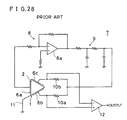
- Fig. 28 is a circuit diagram showing an example of such vibrating gyroscope.
- the other electrode 6a of the piezoelectric element 3a for feedback of the vibrator 1 constitutes a portion of feedback loop for driving the vibrator 1, and through an inversion amplifier circuit 8 having an operation amplifier 8a, is connected, for example, to the input side of a phase correcting circuit 9 consisting of a 2-stage RC filter.
- the output side of the phase correcting circuit 9 is connected respectively to the electrodes 6b and 6c of the other piezoelectric elements 3b and 3c, through fixed resistances 10a and lob.
- the vibrating body 2 of the vibrator 1 is grounded by an earth terminal 11 made of a metal.
- the electrodes 6b and 6c of the two piezoelectric elements 3b and 3c are connected respectively to a non-inversion input end and an inversion input end of a differential amplifier 12.
- the vibrator 1 is subjected to self-oscillation.
- the rotational angular velocity can be known by the output of the differential amplifier 12.
- the piezoelectric elements 3a - 3c are bonded to the vibrating body 2, it is difficult to make it in a very small size. That is, in case of making the vibrating body 2 too small, the piezoelectric elements 3a - 3c can not be bonded accurately at the center of the side faces of the vibrating body 2.
- coefficients of thermal expansion of the vibrating body 2 and the piezoelectric elements 3a - 3c are different, so that variations occur at the bonded portion due to changes in atmospheric temperature, thereby causing characteristic variations.
- the present invention is directed to a vibrator including a columnar vibrating body consisting of a piezoelectric material, and, at least, three electrodes formed on the side faces of the vibrating body.
- a piezoelectric material is used as the vibrating body and a constant elastic metal material is not used. Since the vibrating body is formed with the piezoelectric material, when this vibrating body is polarized, the vibrating body itself bends and vibrates by applying the signal to the electrodes.
- the electrode is formed on the side face of the vibrating body, for example, by the vacuum evaporation and sputtering.
- This vibrator performs self-oscillation when a driving feedback loop is connected between, at least, one electrode and the other electrodes.
- the vibrating body is not needed to be grounded.
- a phase at a resonance point becomes 0° or 180°, so that a phase correcting circuit is not necessary in the driving feedback loop.
- a vibrator which is less expensive and possible to be made very smaller, and in which characteristic variations can be minimized and moreover, can be driven with a simple circuit is obtained.
- Fig. 1 is a perspective view showing one embodiment of the present invention
- Fig. 2 is a sectional view taken along the line II-II of Fig. 1.
- the vibrator 20 includes a regular triangle columnar vibrating body 22 consisting of, for example, a piezoelectric material such as crystal and ceramics.
- the vibrating body 22 as indicated by the arrow in Fig. 2, shows a polarization or piezoelectricity in the direction generally orthogonal to one side face.
- the vibrating body 22 is formed by, for example, the following method.
- a piezoelectric plate consisting of a piezoelectric material having a generally same thickness as the height of vibrating body 22 is prepared. Then, a DC voltage is applied between two surfaces of the piezoelectric plate to polarize the piezoelectric plate in the direction generally orthogonal to the surface. And then, the piezoelectric plate is cut into a regular triangle columnar shape, such that the polarized piezoelectric plate surface makes one side face, to form the vibrating body 22.
- external electrodes 24a, 24b and 24c are formed respectively. These external electrodes 24a - 24c are formed respectively by an electrode material such as gold, silver, copper, nickel or aluminum by, for example, a vacuum evaporation and sputtering method. Therefore, even when the vibrating body 22 is made in a small size, the external electrodes 24a - 24c are formed accurately thereon.
- the vibrating body 22 may be polarized by using the external electrodes, after forming the external electrodes 24a - 24c.
- the vibrator 20 since the piezoelectric material is used as the vibrating body 22 and the constant elastic metal material is not used, it is less expensive as compared with the conventional vibrator shown in Fig. 26 and Fig. 27. Besides, even when the vibrating body 22 is made smaller, the external electrodes 24a - 24c can be formed accurately thereon, so that it can be made in a very small size. Therefore, this vibrator 20 may be used effectively in an apparatus such as a vibrating gyroscope for preventing shaking of hands in a camera.
- one external electrode 24a is used for feedback and the other two external electrodes 24b and 24c are used for driving and detection.
- the external electrode 24a of the vibrator 20 constitutes a portion of feedback loop for driving the vibrator 20, and is connected to the input side of an inversion amplifier circuit 32 having an operation amplifier 32a.
- the output side of the inversion amplifier circuit 32 is connected to, for example, the input side of an RC filter 34 for preventing a spurious.
- the output side of the RC filter 34 is connected respectively to the other two external electrodes 24b and 24c through fixed resistances 36a and 36b.
- the RC filter 34 may not, particularly, be installed. In this case, the output side of the inversion amplifier circuit 32 is connected respectively to the two electrodes 24b and 24c through the fixed resistances 36a and 36b.
- the two external electrodes 24b and 24c are connected respectively to the non-inversion input end and the inversion input end of a differential amplifier 38.
- the output from the external electrode 24a of the vibrator 20 is fed back to the two external electrodes 24b and 24c of the vibrator 20, through the inversion amplifier circuit 32 and so on.
- the vibrator 20 performs self oscillation.
- a phase correcting circuit is not necessary in a feedback loop for driving the vibrator, and can be driven by a simple circuit.
- the vibrating body 22 is formed with the piezoelectric material, the piezoelectric elements are not necessary to be bonded to the side faces of the vibrating body as the conventional one. Thus, variations in the bonded portion do not occur due to the difference in heat expansion coefficients between the vibrating body and the piezoelectric element by changes of the atmospheric temperature, results in little characteristic variations.
- the vibrator can be made smaller.
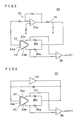
- Fig. 3 is a circuit diagram showing another example of a vibrating gyroscope using the aforesaid vibrator 20.
- an inversion amplifier 40 is used in lieu of an inversion amplifier circuit. That is, the inversion amplifier 40 has its input end connected to the external electrode 24a of the vibrator 20, and its output end connected respectively to the other two external electrodes 24b and 24c through the fixed resistances 36a and 36b. Meanwhile, the input and output ends of the inversion amplifier 40 are connected via a fixed resistance 42.
- the vibrating gyroscope 30 as same as the vibrating gyroscope shown in Fig. 3, it is driven and the rotational angular velocity can be known.
- the vibrating body 22 of the vibrator 20 is formed into a regular triangle column, in the present invention, it may be formed, for example, into a hexagonal column shown in Fig. 5 or any other polygonal column.
- electrodes may be formed respectively on not only three but on four or more side faces.
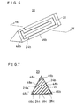
- Fig. 6 is a perspective view showing another embodiment of the present invention
- Fig. 7 is a sectional view taken along the line VII-VII of Fig. 6.
- the vibrator 20 includes the vibrating body 22.
- the vibrating body 22 is consisting of piezoelectric ceramics and piezoelectric crystal such as lithium tantalate, and formed into a regular triangle column.
- interdigital electrodes 24a, 24b and 24c are formed respectively as external electrodes.
- the inter-digital electrode 24a is formed by a pair of comblike electrodes 46a and 48a. These comblike electrodes 46a and 48a are formed by extending in the longitudinal direction of the vibrating body 22, and are arranged so as to incorporate with each other.
- the inter-digital electrode 24b is formed by a pair of comblike electrodes 46b and 48b so as to incorporate with each other
- the inter-digital electrode 24c is formed by a pair of comblike electrodes 46c and 48c which are so arranged to incorporate with each other.
- the comblike electrodes 46a, 46b and 46c of the interdigital electrodes 24a, 24b and 24c are connected respectively to one end of the vibrating body 22. Meanwhile, the vibrating body 22 is polarized from the comblike electrodes 48a toward 46a as indicated by the arrow in Fig. 8. Similarly, the vibrating body 22 is polarized from the comblike electrodes 48b toward 46b, and from'48c toward 46c.
- the comblike electrodes 48a, 48b and 48c may be connected, and an electric field is applied between these electrodes and the comblike electrodes 46a, 46b and 46c.
- the comblike electrodes 48a, 48b and 48c may be formed so as to be connected with each other at the other end of the vibrating body 22, and after polarizing the vibrating body 22, the comblike electrodes 48a, 48b and 48c may be cut off.
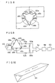
- an angular velocity detecting circuit as shown in Fig. 9 is used. That is, an oscillation circuit output source 50 is connected between the comblike electrodes 46A - 48b is connected to one input side of the differential amplifier circuit 54 via a resistance 52a, and the comblike electrode 48c is connected to the other input side of the differential amplifier circuit 54 via a resistance 52b. Moreover, the comblike electrodes 46a - 46c are connected to one input side of the differential amplifier circuit 54 via a separate resistance 56a, and further, to the other input side of the differential amplifier circuit 54 via a resistance 56b.
- the output side of the differential amplifier circuit 54 is connected to a synchronous detection circuit 58, which is in turn connected to ripple filter 60.
- the vibrating body 22 In the vibrator 20, when the signal from the oscillation circuit output source 50 is applied and the comblike electrode 48a is made positive and the comblike electrode 46a is made negative as shown in Fig. 10, the vibrating body 22 extends laterally and contracts longitudinally. When the signal is reversed, the vibrating body 22 contracts laterally, and extends longitudinally. In such a way, the vibrating body 22 bends and vibrates in the direction orthogonal to the plane whereon the comblike electrode 48a is formed.
- the inter-digital electrodes 24a, 24b and 24c can be used for polarization of the vibrating body 22, as well as, for excitation and output voltage detection.
- the vibrator 20 it is not necessary to form an electrode separately for polarization and its manufacturing method is simple, results in a low manufacturing cost.
- the oscillation circuit output source 50 may be connected between the comblike electrodes 48a, 48b and the comblike electrode 48c.
- the vibrating body 22 bends and vibrates in the direction orthogonal to the plane whereon the comblike electrode 48c is formed.
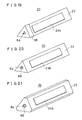
- inter-digital electrodes 24a - 24c for example, as shown in Fig. 12, it may formed such that the teeth of a comb extend in the lateral direction of the side face of the vibrating body 22. Also in this case, polarization is effected between the opposing comblike electrodes.
- the number of teeth of the comblike electrode can be changed optionally. By changing the number of teeth, the capacity can be controlled.
- Fig. 13 is a perspective view showing still another embodiment of the present invention
- Fig. 14 is a sectional view taken along the line XIV-XIV of Fig. 13.
- the vibrator 20 includes the vibrating body 22.
- the vibrating body 22 is formed, for example, into a regular triangle column by piezoelectric ceramics.
- a regular triangle columnar through hole 64 is formed directing axially thereof.
- the vibrating body 22 is polarized radially from its inner circumferential surface toward the peripheral surface.
- the vibrating body 22 is supported in the neighborhood of its nodal point.
- an internal electrode 66 is formed Throughout the inner circumferential surface of the vibrating body 22, an internal electrode 66 is formed. More strictlyover, on three side faces of the vibrating body 22, external electrodes 24a, 24b and 24c are formed respectively at the center. These internal electrode 66 and the external electrodes 24a - 24c are formed by, for example, silver or the like by silver paste sintering, plating, vacuum evaporation and sputtering methods.
- the vibrating body 22 formed with the through hole 64 is prepared. Throughout the inner circumferential surface and peripheral surface of the vibrating body 22, as shown in Fig. 15, the internal electrode 66 and a peripheral electrode 70 are formed by the silver paste sintering, plating, vacuum evaporation and sputtering methods. Then, by applying an electric field between the internal electrode 66 and the peripheral electrode 70, as indicated by the arrow, the vibrating body 22 is polarized radially from the inner circumferential surface toward the peripheral surface.
- the external electrodes 24a, 24b and 24c are formed.
- an angular velocity detecting circuit as shown in Fig. 16 is used. That is, resistances 72, 74 are connected to the two external electrodes 24a, 24b. And, an oscillation circuit output source 50 is connected between the resistance 72, 74 and the other external electrode 24c. By the signal from this oscillation circuit output source 50, the vibrating body 22 bends and vibrates in the direction orthogonal to the surface of the external electrode 24c.
- separate resistances 78, 80 are connected to the two external electrodes 24a, 24b.
- the resistances 78, 80 are connected to the input side of the differential amplifier circuit 54.
- the output side of the differential amplifier circuit 54 is connected to a synchronous detection circuit 58, which is in turn connected to a ripple filter 60.
- the output obtained from the differential amplifier circuit 54 is detected synchronously in the synchronous detection circuit 58, and by passing through the ripple filter 60, the DC output is obtained. Accordingly, by measuring the DC output, the rotational angular velocity applied to the vibrator 20 can be measured.
- the internal electrode 66 and the external electrodes 24a - 24c may be formed in the vibrating body 22 formed with a piezoelectrical material. These electrodes may be formed simply by the silver paste sintering, plating, vacuum evaporation and sputtering.
- the external electrodes 24a - 24c may be formed by removing unnecessary portions of the peripheral electrode 70.
- the peripheral electrode 70 may be used for polarizing the vibrating body 22. That is, in the vibrator 20, the external electrodes 24a - 24c can be formed by utilizing the peripheral electrode 70 for polarizing the vibrating body 22. Accordingly, the vibrator 20 can be manufactured simply and at low cost as compared with the conventional vibrator.
- the resonance frequency can be reduced and its sensitivity can be improved.
- the vibrating body 22 can be made smaller than that without the through hole.
- the oscillation circuit output source 50 is connected between the external electrodes 24a, 24b and the external electrode 24c, as shown in Fig. 17, the oscillation circuit output source 50 may be connected between the internal electrode 66 and the external electrode 24c. Also, as shown in Fig. 18, the oscillation circuit output source 50 may be connected between the internal electrode 66 and the two external electrodes 24a, 24b. In order to accomplish the circuit configuration as these embodiments, as shown in Fig. 19, the internal electrode 66 may be formed by drawing from the end face to the side face of the vibrating body 22.
- a shape of the through hole 64 is not limited to the triangle column, it may be in the other shape such as a cylindrical column as shown in Fig. 20. Furthermore, a shape of the vibrating body 22 is not limited to the triangle column, it may be a hexagonal column ash shown in Fig. 21 or any other polygonal column.
- Fig. 22 is a perspective view showing another embodiment of the present invention
- Fig. 23 is a sectional view taken along the line XXIII-XXIII of Fig. 22.
- the vibrating body 22 is formed cylindrically.
- a circular through hole 64 directing axially is formed in the vibrating body 22.
- the vibrating body 22 is polarized radially from its inner circumferential surface toward the peripheral surface.
- the vibrating body 22 is supported in the neighborhood of its nodal point.
- an internal electrode 66 is formed.
- external electrodes 24a, 24b and 24c are formed on the peripheral surface of the vibrating body 22, generally trisecting its periphery. Meanwhile, these external electrodes 24a - 24c are so formed that their faces are spaced from each other.
- the internal electrode 66 and peripheral electrode 70 are formed. And, by applying an electric field between the internal electrode 66 and the peripheral electrode 70, as indicated by the arrow, the vibrating body 22 is polarized radially from its inner circumferential surface toward the peripheral surface.
- this vibrator 20 As an angular velocity sensor, an angular velocity detecting circuit similar to that shown in Fig. 16, Fig. 17 and Fig. 18 is used. Thereby, the rotational angular velocity can be measured in the same manner as the vibrator 20 shown in Fig. 13 and Fig. 14.
- the vibrating body 22 itself is formed cylindrically, a metal mold for manufacturing the vibrating body 22 can be made simply. Accordingly, this vibrator 20 can be manufactured simply and at low cost, as compared with the conventional angular velocity sensor. Also, in this case, if the machining accuracy is obtained at the beginning, the resonance frequencies at bending and vibrating of the vibrating body 22 in various directions are liable to coincide, thus as compared with the other shape, the machining accuracy can be easily controlled by centerless grinding and so on.
- this vibrator 20 by forming a through hole 64 in the cylindrical vibrating body 22, as compared with the vibrating body of the same shape without the through hole, the resonance frequency can be reduced and its sensitivity can be improved. In case of the equal sensitivity, the vibrating body 22 can be made smaller than that with no through hole.
- the internal electrode 66 As a shape of the internal electrode 66, as shown in Fig. 25, it may be formed by drawing from the end face to the side face of the vibrating body 22.
Landscapes
- Engineering & Computer Science (AREA)
- Physics & Mathematics (AREA)
- General Physics & Mathematics (AREA)
- Mechanical Engineering (AREA)
- Manufacturing & Machinery (AREA)
- Radar, Positioning & Navigation (AREA)
- Remote Sensing (AREA)
- Gyroscopes (AREA)
Abstract
Description
- The present invention relates to a vibrator, particularly, it relates to a vibrator used in an apparatus utilizing vibration such as a vibrating gyroscope or an angular velocity sensor, used in detecting shaking of hands in a video camera and attitude control of an automobile.
- Fig. 26 is a perspective view showing an example of conventional vibrator and Fig. 27 is a transverse sectional view thereof. The
vibrator 1 includes a regular triangle columnar vibratingbody 2 consisting of a constant elastic metal material such as elinvar, and at the center of three side faces of the vibratingbody 2, strippedpiezoelectric element piezoelectric element 3a is consisting ofelectrodes piezoelectric layer 4a, one electrode Sa being bonded to one side face of thevibrating body 2. Similarly, thepiezoelectric elements electrodes piezoelectric layers 4b and 4c, oneelectrodes body 2. The vibratingbody 2 is supported by a supporting member in the neighborhood of its nodal point. - When using the vibrating gyroscope, for example, one
piezoelectric element 3a is used for feedback and the other twopiezoelectric elements 4b and 4c are used for driving and detection, and furthermore, thevibrating body 2 is grounded. - Fig. 28 is a circuit diagram showing an example of such vibrating gyroscope.
- That is, in the vibrating
gyroscope 7, theother electrode 6a of thepiezoelectric element 3a for feedback of thevibrator 1 constitutes a portion of feedback loop for driving thevibrator 1, and through an inversion amplifier circuit 8 having anoperation amplifier 8a, is connected, for example, to the input side of aphase correcting circuit 9 consisting of a 2-stage RC filter. The output side of thephase correcting circuit 9 is connected respectively to theelectrodes piezoelectric elements fixed resistances 10a and lob. The vibratingbody 2 of thevibrator 1 is grounded by anearth terminal 11 made of a metal. Meanwhile, theelectrodes piezoelectric elements differential amplifier 12. - In the
vibrating gyroscope 7, - since the output from thepiezoelectric element 3a is fed back to the twopiezoelectric elements vibrator 1 is subjected to self-oscillation. - Then, in this state, when the
vibrator 1 is rotated about its axis, a voltage corresponding to its rotational angular velocity is produced between the twopiezoelectric elements differential amplifier 12 and outputted. - Accordingly, in the vibrating
gyroscope 7, the rotational angular velocity can be known by the output of thedifferential amplifier 12. - However, in the
aforesaid vibrator 1, since thepiezoelectric elements 3a - 3c are bonded to the vibratingbody 2, it is difficult to make it in a very small size. That is, in case of making thevibrating body 2 too small, thepiezoelectric elements 3a - 3c can not be bonded accurately at the center of the side faces of the vibratingbody 2. - Also, in the
vibrator 1, since a constant elastic metal material is used as thevibrator body 2, it is very costly. - Moreover, coefficients of thermal expansion of the vibrating
body 2 and thepiezoelectric elements 3a - 3c are different, so that variations occur at the bonded portion due to changes in atmospheric temperature, thereby causing characteristic variations. - In addition, for driving the
vibrator 1, not only the vibratingbody 2 must be grounded, but also the phase correcting circuit is necessary in a feedback loop for driving, the circuit configuration becomes complicated. - Therefore, it is a primary object of the present invention to provide a vibrator which is less expensive and possible to be made very smaller, and in which characteristic variations can be minimized and moreover, it can be driven with a simple circuit.
- The present invention is directed to a vibrator including a columnar vibrating body consisting of a piezoelectric material, and, at least, three electrodes formed on the side faces of the vibrating body.
- In the vibrator, a piezoelectric material is used as the vibrating body and a constant elastic metal material is not used. Since the vibrating body is formed with the piezoelectric material, when this vibrating body is polarized, the vibrating body itself bends and vibrates by applying the signal to the electrodes.
- Moreover, on the side face of the the vibrating body, piezoelectric element is not bonded but the electrode is formed. In this case, even when the vibrating body is formed smaller, the electrode can be formed accurately on the side face of the vibrating body, for example, by the vacuum evaporation and sputtering.
- This vibrator performs self-oscillation when a driving feedback loop is connected between, at least, one electrode and the other electrodes. In this case, the vibrating body is not needed to be grounded. Furthermore, as the vibrating body is not grounded, a phase at a resonance point becomes 0° or 180°, so that a phase correcting circuit is not necessary in the driving feedback loop.
- According to the present invention, a vibrator which is less expensive and possible to be made very smaller, and in which characteristic variations can be minimized and moreover, can be driven with a simple circuit is obtained.
- These and other objects, features, aspects and advantages of the present invention will become more apparent from the detailed description of the following embodiments described in connection with the accompanying drawings.
-
- Fig. 1 is a perspective view showing one embodiment of the present invention, and Fig. 2 is a sectional view taken along the line II-II of Fig. 1.
- Fig. 3 is a circuit diagram showing an example of a vibrating gyroscope using a vibrator shown in Fig. 1 and Fig. 2.
- Fig. 4 is a circuit diagram showing another example of a vibrating gyroscope using a vibrator shown in Fig. 1 and Fig. 2.
- Fig. 5 is a transverse sectional view showing a modified example of a vibrator shown in Fig. 1 and Fig. 2.
- Fig. 6 is a perspective view showing another embodiment of the present invention, and Fig. 7 is a sectional view taken along the line VII-VII of Fig. 6.
- Fig. 8 is an illustrative view showing the state wherein a vibrator shown in Fig. 6 and Fig. 7 is polarized.
- Fig. 9 is a circuit diagram showing an example of an angular velocity detecting circuit using a vibrator shown in Fig. 6 and Fig. 7.
- Fig. 10 is an illustrative view showing the state wherein a vibrator is excited by a circuit shown in Fig. 9.
- Fig. 11 is a circuit diagram showing another example of an angular velocity detecting circuit shown in Fig. 9.
- Fig. 12 is a perspective view showing another example of a vibrator shown in Fig. 6 and Fig. 7.
- Fig. 13 is a perspective view showing still another embodiment of the present invention, and Fig. 14 is a sectional view taken along the line XIV-XIV of Fig. 13.
- Fig. 15 is a perspective view showing a process of manufacturing a vibrator shown in Fig. 13 and big. 14.
- Fig. 16 is a circuit diagram showing an example of an angular velocity detecting circuit using a vibrator shown in Fig. 13 and Fig. 14.
- Fig. 17 is a circuit diagram showing another example of an angular velocity detecting circuit shown in Fig. 16.
- Fig. 18 is a circuit diagram showing still another example of an angular velocity detecting circuit shown in Fig. 16.
- Fig. 19 is a perspective view showing another example of a vibrator shown in Fig. 13 and Fig. 14.
- Fig. 20 is a perspective view showing still another example of a vibrator shown in Fig. 13 and Fig. 14.
- Fig. 21 is a perspective view showing a separate example of a vibrator shown in Fig. 13 and Fig. 14.
- Fig. 22 is a perspective view showing a separate embodiment of the present invention, and Fig. 23 is a sectional view taken along the line XXIII-XXIII of Fig. 22.
- Fig. 24 is a perspective view showing a process for manufacturing a vibrator shown in Fig. 22 and Fig. 23.
- Fig. 25 is a perspective view showing another example of a vibrator shown in Fig. 22 and Fig. 23.
- Fig. 26 is a perspective view showing an example of a conventional vibrator which is the background of the present invention.
- Fig. 27 is a transverse sectional view of a conventional vibrator shown in Fig. 26.
- Fig. 28 is a circuit diagram showing an example of a vibrating gyroscope using a vibrator shown in Fig. 26 and Fig. 27.
- Fig. 1 is a perspective view showing one embodiment of the present invention, and Fig. 2 is a sectional view taken along the line II-II of Fig. 1.
- The
vibrator 20 includes a regular triangle columnar vibratingbody 22 consisting of, for example, a piezoelectric material such as crystal and ceramics. The vibratingbody 22, as indicated by the arrow in Fig. 2, shows a polarization or piezoelectricity in the direction generally orthogonal to one side face. The vibratingbody 22 is formed by, for example, the following method. - First, a piezoelectric plate consisting of a piezoelectric material having a generally same thickness as the height of vibrating
body 22 is prepared. Then, a DC voltage is applied between two surfaces of the piezoelectric plate to polarize the piezoelectric plate in the direction generally orthogonal to the surface. And then, the piezoelectric plate is cut into a regular triangle columnar shape, such that the polarized piezoelectric plate surface makes one side face, to form the vibratingbody 22. - At the center of the three side faces of the vibrating
body 22,external electrodes external electrodes 24a - 24c are formed respectively by an electrode material such as gold, silver, copper, nickel or aluminum by, for example, a vacuum evaporation and sputtering method. Therefore, even when the vibratingbody 22 is made in a small size, theexternal electrodes 24a - 24c are formed accurately thereon. The vibratingbody 22 may be polarized by using the external electrodes, after forming theexternal electrodes 24a - 24c. - In the
vibrator 20, since the piezoelectric material is used as the vibratingbody 22 and the constant elastic metal material is not used, it is less expensive as compared with the conventional vibrator shown in Fig. 26 and Fig. 27. Besides, even when the vibratingbody 22 is made smaller, theexternal electrodes 24a - 24c can be formed accurately thereon, so that it can be made in a very small size. Therefore, thisvibrator 20 may be used effectively in an apparatus such as a vibrating gyroscope for preventing shaking of hands in a camera. - Next, with reference to Fig. 3, the vibrating gyroscope using the
vibrator 20 will be described. - In the vibrating
gyroscope 30, in thevibrator 20, for example, oneexternal electrode 24a is used for feedback and the other twoexternal electrodes - Thus, the
external electrode 24a of thevibrator 20 constitutes a portion of feedback loop for driving thevibrator 20, and is connected to the input side of aninversion amplifier circuit 32 having anoperation amplifier 32a. The output side of theinversion amplifier circuit 32 is connected to, for example, the input side of anRC filter 34 for preventing a spurious. The output side of theRC filter 34 is connected respectively to the other twoexternal electrodes resistances RC filter 34 may not, particularly, be installed. In this case, the output side of theinversion amplifier circuit 32 is connected respectively to the twoelectrodes resistances - Meanwhile, the two
external electrodes differential amplifier 38. - In the vibrating
gyroscope 30, the output from theexternal electrode 24a of thevibrator 20 is fed back to the twoexternal electrodes vibrator 20, through theinversion amplifier circuit 32 and so on. Thus, thevibrator 20 performs self oscillation. - Then, in this state, as the vibrator ,20 is rotated about it axis, a coriolis force is exerted in the direction orthogonal to the bending and vibrating direct%on. Thus, the vibrating direction of the vibrating
body 22 shifts from the non-rotational vibrating direction. Therefore, a voltage corresponding to the rotational angular velocity is produced between the two external electrodes. 24b and 24c of thevibrator 20. This voltage is detected in thedifferential amplifier 38 and outputted. Accordingly, in the vibratinggyroscope 30, the rotational angular velocity can be known by the output of thedifferential amplifier 38. - As aforementioned, in the
vibrator 20, as compared with the conventional vibrator shown in Fig. 26 and Fig. 27, a phase correcting circuit is not necessary in a feedback loop for driving the vibrator, and can be driven by a simple circuit. - Also, in the
vibrator 20, since the vibratingbody 22 is formed with the piezoelectric material, the piezoelectric elements are not necessary to be bonded to the side faces of the vibrating body as the conventional one. Thus, variations in the bonded portion do not occur due to the difference in heat expansion coefficients between the vibrating body and the piezoelectric element by changes of the atmospheric temperature, results in little characteristic variations. - Moreover, since the piezoelectric element is not bonded to the vibrating body and the external- electrodes can be formed by the vacuum evaporation or sputtering method, the vibrator can be made smaller.
- Fig. 3 is a circuit diagram showing another example of a vibrating gyroscope using the
aforesaid vibrator 20. - In this vibrating
gyroscope 30, particularly, as a feedback loop for driving thevibrator 20, aninversion amplifier 40 is used in lieu of an inversion amplifier circuit. That is, theinversion amplifier 40 has its input end connected to theexternal electrode 24a of thevibrator 20, and its output end connected respectively to the other twoexternal electrodes resistances inversion amplifier 40 are connected via a fixedresistance 42. - Also, in the vibrating
gyroscope 30, as same as the vibrating gyroscope shown in Fig. 3, it is driven and the rotational angular velocity can be known. - In the embodiment aforementioned, though the vibrating
body 22 of thevibrator 20 is formed into a regular triangle column, in the present invention, it may be formed, for example, into a hexagonal column shown in Fig. 5 or any other polygonal column. When the vibrating body is formed with four or more side faces, electrodes may be formed respectively on not only three but on four or more side faces. - Fig. 6 is a perspective view showing another embodiment of the present invention, and Fig. 7 is a sectional view taken along the line VII-VII of Fig. 6. The
vibrator 20 includes the vibratingbody 22. The vibratingbody 22 is consisting of piezoelectric ceramics and piezoelectric crystal such as lithium tantalate, and formed into a regular triangle column. - On three side faces of the vibrating
body 22,interdigital electrodes inter-digital electrode 24a is formed by a pair ofcomblike electrodes comblike electrodes body 22, and are arranged so as to incorporate with each other. - Similarly, the
inter-digital electrode 24b is formed by a pair ofcomblike electrodes inter-digital electrode 24c is formed by a pair ofcomblike electrodes - The
comblike electrodes interdigital electrodes body 22. Meanwhile, the vibratingbody 22 is polarized from thecomblike electrodes 48a toward 46a as indicated by the arrow in Fig. 8. Similarly, the vibratingbody 22 is polarized from thecomblike electrodes 48b toward 46b, and from'48c toward 46c. - For polarization, as shown in Fig. 8, the
comblike electrodes comblike electrodes comblike electrodes body 22, and after polarizing the vibratingbody 22, thecomblike electrodes - For using the
vibrator 20 as an angular velocity sensor, for example, an angular velocity detecting circuit as shown in Fig. 9 is used. That is, an oscillationcircuit output source 50 is connected between the comblike electrodes 46A - 48b is connected to one input side of thedifferential amplifier circuit 54 via aresistance 52a, and thecomblike electrode 48c is connected to the other input side of thedifferential amplifier circuit 54 via aresistance 52b. Moreover, thecomblike electrodes 46a - 46c are connected to one input side of thedifferential amplifier circuit 54 via aseparate resistance 56a, and further, to the other input side of thedifferential amplifier circuit 54 via aresistance 56b. - The output side of the
differential amplifier circuit 54 is connected to asynchronous detection circuit 58, which is in turn connected to ripplefilter 60. - In the
vibrator 20, when the signal from the oscillationcircuit output source 50 is applied and thecomblike electrode 48a is made positive and thecomblike electrode 46a is made negative as shown in Fig. 10, the vibratingbody 22 extends laterally and contracts longitudinally. When the signal is reversed, the vibratingbody 22 contracts laterally, and extends longitudinally. In such a way, the vibratingbody 22 bends and vibrates in the direction orthogonal to the plane whereon thecomblike electrode 48a is formed. - When the
vibrator 20 is rotated about its axis, a coriolis force is exerted in the direction orthogonal to the bending and vibrating direction. Thus, the vibrating direction of the vibratingbody 22 is shifted from the non-rotational vibrating direction. Therefore, difference of output voltages produced between thecomblike electrodes differential amplifier circuit 54. The output from thedifferential amplifier circuit 54 is detected in thesynchronous detection circuit 58, and by further passing through theripple filter 60, the DC output is obtained. Accordingly, by measuring the DC output, the rotational angular velocity applied on thevibrator 20 can be measured. - In the
vibrator 20, theinter-digital electrodes body 22, as well as, for excitation and output voltage detection. Thus, in thevibrator 20, it is not necessary to form an electrode separately for polarization and its manufacturing method is simple, results in a low manufacturing cost. - Incidentally, in the embodiment aforementioned, though the oscillation
circuit output source 50 is connected between thecomblike electrode 48a and thecomblike electrodes 46acircuit output source 50 may be connected between thecomblike electrodes comblike electrode 48c. In this case, the vibratingbody 22 bends and vibrates in the direction orthogonal to the plane whereon thecomblike electrode 48c is formed. - As the shape of
inter-digital electrodes 24a - 24c, for example, as shown in Fig. 12, it may formed such that the teeth of a comb extend in the lateral direction of the side face of the vibratingbody 22. Also in this case, polarization is effected between the opposing comblike electrodes. - The number of teeth of the comblike electrode can be changed optionally. By changing the number of teeth, the capacity can be controlled.
- Fig. 13 is a perspective view showing still another embodiment of the present invention, and Fig. 14 is a sectional view taken along the line XIV-XIV of Fig. 13. The
vibrator 20 includes the vibratingbody 22. The vibratingbody 22 is formed, for example, into a regular triangle column by piezoelectric ceramics. In the vibratingbody 22, a regular triangle columnar throughhole 64 is formed directing axially thereof. Meanwhile, the vibratingbody 22 is polarized radially from its inner circumferential surface toward the peripheral surface. The vibratingbody 22 is supported in the neighborhood of its nodal point. - Throughout the inner circumferential surface of the vibrating
body 22, aninternal electrode 66 is formed. Moreover, on three side faces of the vibratingbody 22,external electrodes internal electrode 66 and theexternal electrodes 24a - 24c are formed by, for example, silver or the like by silver paste sintering, plating, vacuum evaporation and sputtering methods. - For manufacturing the
vibrator 20, the vibratingbody 22 formed with the throughhole 64 is prepared. Throughout the inner circumferential surface and peripheral surface of the vibratingbody 22, as shown in Fig. 15, theinternal electrode 66 and aperipheral electrode 70 are formed by the silver paste sintering, plating, vacuum evaporation and sputtering methods. Then, by applying an electric field between theinternal electrode 66 and theperipheral electrode 70, as indicated by the arrow, the vibratingbody 22 is polarized radially from the inner circumferential surface toward the peripheral surface. - Next, by removing unnecessary portions of the
peripheral electrode 70, theexternal electrodes - For using the
vibrator 20 as an angular velocity sensor, for example, an angular velocity detecting circuit as shown in Fig. 16 is used. That is,resistances external electrodes circuit output source 50 is connected between theresistance external electrode 24c. By the signal from this oscillationcircuit output source 50, the vibratingbody 22 bends and vibrates in the direction orthogonal to the surface of theexternal electrode 24c. - Meanwhile,
separate resistances external electrodes resistances differential amplifier circuit 54. Furthermore, the output side of thedifferential amplifier circuit 54 is connected to asynchronous detection circuit 58, which is in turn connected to aripple filter 60. - In the state wherein the vibrating
body 22 bends and vibrates by the signal from the oscillationcircuit output source 50, when the vibratingbody 22 is rotated about its axis, corresponding to the rotational angular velocity, a coriolis force is exerted in the direction orthogonal to the vibrating direction. Thereby, the vibrating direction of the vibratingbody 22 shifts from the non-rotational vibrating direction. Thus, difference of output voltages is produced between the twoexternal electrodes differential amplifier circuit 54. - The output obtained from the
differential amplifier circuit 54 is detected synchronously in thesynchronous detection circuit 58, and by passing through theripple filter 60, the DC output is obtained. Accordingly, by measuring the DC output, the rotational angular velocity applied to thevibrator 20 can be measured. - In the
vibrator 20, theinternal electrode 66 and theexternal electrodes 24a - 24c may be formed in the vibratingbody 22 formed with a piezoelectrical material. These electrodes may be formed simply by the silver paste sintering, plating, vacuum evaporation and sputtering. - Besides, the
external electrodes 24a - 24c may be formed by removing unnecessary portions of theperipheral electrode 70. Theperipheral electrode 70 may be used for polarizing the vibratingbody 22. That is, in thevibrator 20, theexternal electrodes 24a - 24c can be formed by utilizing theperipheral electrode 70 for polarizing the vibratingbody 22. Accordingly, thevibrator 20 can be manufactured simply and at low cost as compared with the conventional vibrator. - Also, by forming the through
hole 64 in the trianglecolumnar vibrating body 22, as compared with the vibrating body of the same shape with no through hole, the resonance frequency can be reduced and its sensitivity can be improved. In case of the equal sensitivity, the vibratingbody 22 can be made smaller than that without the through hole. - In the embodiment aforementioned, though the oscillation
circuit output source 50 is connected between theexternal electrodes external electrode 24c, as shown in Fig. 17, the oscillationcircuit output source 50 may be connected between theinternal electrode 66 and theexternal electrode 24c. Also, as shown in Fig. 18, the oscillationcircuit output source 50 may be connected between theinternal electrode 66 and the twoexternal electrodes internal electrode 66 may be formed by drawing from the end face to the side face of the vibratingbody 22. - A shape of the through
hole 64 is not limited to the triangle column, it may be in the other shape such as a cylindrical column as shown in Fig. 20. Furthermore, a shape of the vibratingbody 22 is not limited to the triangle column, it may be a hexagonal column ash shown in Fig. 21 or any other polygonal column. - Fig. 22 is a perspective view showing another embodiment of the present invention, and Fig. 23 is a sectional view taken along the line XXIII-XXIII of Fig. 22. In this embodiment, the vibrating
body 22 is formed cylindrically. In the vibratingbody 22, a circular throughhole 64 directing axially is formed. Meanwhile, the vibratingbody 22 is polarized radially from its inner circumferential surface toward the peripheral surface. The vibratingbody 22 is supported in the neighborhood of its nodal point. - Throughout the inner circumferential surface of the vibrating
body 22, aninternal electrode 66 is formed. On the peripheral surface of the vibratingbody 22, generally trisecting its periphery,external electrodes external electrodes 24a - 24c are so formed that their faces are spaced from each other. - In manufacturing the
vibrator 20, as shown in Fig. 24, theinternal electrode 66 andperipheral electrode 70 are formed. And, by applying an electric field between theinternal electrode 66 and theperipheral electrode 70, as indicated by the arrow, the vibratingbody 22 is polarized radially from its inner circumferential surface toward the peripheral surface. - Next, by removing unnecessary portions of the
peripheral electrode 70,external electrodes - In order to use this
vibrator 20 as an angular velocity sensor, an angular velocity detecting circuit similar to that shown in Fig. 16, Fig. 17 and Fig. 18 is used. Thereby, the rotational angular velocity can be measured in the same manner as thevibrator 20 shown in Fig. 13 and Fig. 14. - In this
vibrator 20, since the vibratingbody 22 is formed cylindrically, uniform polarization can be effected between theinternal electrode 66 and theexternal electrodes - Besides, since the vibrating
body 22 itself is formed cylindrically, a metal mold for manufacturing the vibratingbody 22 can be made simply. Accordingly, thisvibrator 20 can be manufactured simply and at low cost, as compared with the conventional angular velocity sensor. Also, in this case, if the machining accuracy is obtained at the beginning, the resonance frequencies at bending and vibrating of the vibratingbody 22 in various directions are liable to coincide, thus as compared with the other shape, the machining accuracy can be easily controlled by centerless grinding and so on. - Also, in this
vibrator 20, by forming a throughhole 64 in the cylindrical vibratingbody 22, as compared with the vibrating body of the same shape without the through hole, the resonance frequency can be reduced and its sensitivity can be improved. In case of the equal sensitivity, the vibratingbody 22 can be made smaller than that with no through hole. - As a shape of the
internal electrode 66, as shown in Fig. 25, it may be formed by drawing from the end face to the side face of the vibratingbody 22. - While the invention has been particularly described and shown, it is to be understood that such description is for illustrative purposes and examples only and not of limitation, the spirit and scope of the invention is determined solely by the terms of the appended claims.
Claims (6)
said vibrating body is polarized between said pair of comblike electrodes of said inter-digital electrodes.
said vibrating body is polarized in the direction from the inner circumferential surface to the peripheral surface.
said external electrodes are arranged in a spaced relation in the circumferential direction of said vibrating body, and said vibrating body is polarized in the direction from the inner circumferential surface to the peripheral surface.
Applications Claiming Priority (8)
| Application Number | Priority Date | Filing Date | Title |
|---|---|---|---|
| JP290757/89 | 1989-11-07 | ||
| JP1290757A JP2608536B2 (en) | 1989-11-07 | 1989-11-07 | Vibrator |
| JP225843/90 | 1990-08-27 | ||
| JP2225844A JP2508384B2 (en) | 1990-08-27 | 1990-08-27 | Angular velocity sensor |
| JP2225843A JP2508383B2 (en) | 1990-08-27 | 1990-08-27 | Angular velocity sensor |
| JP225842/90 | 1990-08-27 | ||
| JP225844/90 | 1990-08-27 | ||
| JP2225842A JP2508382B2 (en) | 1990-08-27 | 1990-08-27 | Angular velocity sensor |
Publications (3)
| Publication Number | Publication Date |
|---|---|
| EP0427177A2 true EP0427177A2 (en) | 1991-05-15 |
| EP0427177A3 EP0427177A3 (en) | 1992-07-22 |
| EP0427177B1 EP0427177B1 (en) | 1995-02-08 |
Family
ID=27477194
Family Applications (1)
| Application Number | Title | Priority Date | Filing Date |
|---|---|---|---|
| EP90121146A Expired - Lifetime EP0427177B1 (en) | 1989-11-07 | 1990-11-05 | Vibrator |
Country Status (3)
| Country | Link |
|---|---|
| US (1) | US5117148A (en) |
| EP (1) | EP0427177B1 (en) |
| DE (1) | DE69016743T2 (en) |
Cited By (3)
| Publication number | Priority date | Publication date | Assignee | Title |
|---|---|---|---|---|
| DE4314535A1 (en) * | 1993-05-03 | 1994-11-10 | Sick Optik Elektronik Erwin | Interferometric gas component measuring instrument |
| EP0732566A1 (en) * | 1995-03-14 | 1996-09-18 | Murata Manufacturing Co., Ltd. | Vibrating gyroscope |
| EP0897100A1 (en) * | 1997-02-17 | 1999-02-17 | Mitutoyo Corporation | Nondirectional touch signal probe |
Families Citing this family (24)
| Publication number | Priority date | Publication date | Assignee | Title |
|---|---|---|---|---|
| US5874674A (en) * | 1988-08-12 | 1999-02-23 | Murata Manufacturing Co., Ltd. | Vibrator including piezoelectric electrodes or detectors arranged to be non-parallel and non-perpendicular to coriolis force direction and vibratory gyroscope using the same |
| US5349857A (en) * | 1988-08-12 | 1994-09-27 | Murata Manufacturing Co., Ltd. | Vibratory gyroscope |
| US5493166A (en) * | 1988-08-12 | 1996-02-20 | Murata Manufacturing Co., Ltd. | Vibrator and vibrating gyroscope using the same |
| EP0517259B1 (en) * | 1991-06-07 | 1996-05-15 | Akai Electric Co., Ltd. | Vibration control apparatus |
| JP2923813B2 (en) * | 1991-06-11 | 1999-07-26 | キヤノン株式会社 | Cantilever displacement element, scanning tunneling microscope using the same, and information processing apparatus |
| JPH0552572A (en) * | 1991-08-28 | 1993-03-02 | Akai Electric Co Ltd | Supporting structure for vibrator |
| DE69310799T2 (en) * | 1992-03-30 | 1997-11-13 | Murata Manufacturing Co | Vibrator with balanced edge areas |
| JP3016986B2 (en) * | 1993-02-17 | 2000-03-06 | 三菱電機株式会社 | Vibrating gyroscope detection circuit |
| EP0645602B1 (en) * | 1993-09-24 | 1998-06-17 | Murata Manufacturing Co., Ltd. | Vibrating gyroscope |
| JP3175489B2 (en) * | 1994-08-24 | 2001-06-11 | 三菱電機株式会社 | Vibrating gyroscope and vibrating gyroscope inspection device |
| JPH08159779A (en) | 1994-12-02 | 1996-06-21 | Murata Mfg Co Ltd | Vibration gyro |
| JP3291968B2 (en) * | 1994-12-15 | 2002-06-17 | 株式会社村田製作所 | Vibrating gyro |
| JP2996137B2 (en) * | 1995-03-31 | 1999-12-27 | 株式会社村田製作所 | Vibrating gyro |
| JPH08278146A (en) * | 1995-04-03 | 1996-10-22 | Murata Mfg Co Ltd | Vibrating gyro |
| US6085740A (en) * | 1996-02-21 | 2000-07-11 | Aerogen, Inc. | Liquid dispensing apparatus and methods |
| JPH09113279A (en) * | 1995-10-16 | 1997-05-02 | Murata Mfg Co Ltd | Vibrational gyro |
| JP2996157B2 (en) * | 1995-10-12 | 1999-12-27 | 株式会社村田製作所 | Vibrating gyro |
| US5698784A (en) * | 1996-01-24 | 1997-12-16 | Gyration, Inc. | Vibratory rate gyroscope and methods of assembly and operation |
| US6457358B1 (en) * | 1999-03-18 | 2002-10-01 | Board Of Regents Of The University Of Nebraska | Tubular coriolis force driven piezoelectric gyroscope system, and method of use |
| US6690351B1 (en) * | 2000-04-06 | 2004-02-10 | Xybernaut Corporation | Computer display optimizer |
| GB0121934D0 (en) * | 2001-09-12 | 2001-10-31 | Europ Technology For Business | Angular rate sensors |
| JP4631329B2 (en) * | 2004-07-01 | 2011-02-16 | パナソニック株式会社 | Angular velocity sensor and manufacturing method thereof |
| DE102016112101B4 (en) * | 2016-07-01 | 2018-08-02 | Physik Instrumente (Pi) Gmbh & Co. Kg | Device comprising an ultrasonic actuator and a mounting device, wherein the ultrasonic actuator is arranged on the mounting device |
| CN110420827B (en) * | 2019-08-12 | 2021-07-27 | 中国科学院微电子研究所 | Ultrasonic transducer array probe |
Citations (6)
| Publication number | Priority date | Publication date | Assignee | Title |
|---|---|---|---|---|
| US2607216A (en) * | 1946-08-16 | 1952-08-19 | Bell Telephone Labor Inc | Torsional interferometer |
| US3258617A (en) * | 1963-02-07 | 1966-06-28 | Avco Corp | Piezoelectric device |
| US3559162A (en) * | 1969-04-14 | 1971-01-26 | Sparton Corp | Unitary directional sonar transducer |
| DE2165680A1 (en) * | 1971-12-30 | 1973-07-05 | Siemens Ag | PIEZOELECTRIC BODY AND METHOD OF POLARIZATION |
| US3871395A (en) * | 1973-02-26 | 1975-03-18 | Fibra Sonics | Ultrasonic/chemical cleaner for contact lenses |
| FR2369690A1 (en) * | 1976-10-29 | 1978-05-26 | Westinghouse Electric Corp | PIEZOELECTRIC DEVICE |
Family Cites Families (9)
| Publication number | Priority date | Publication date | Assignee | Title |
|---|---|---|---|---|
| US2944118A (en) * | 1960-07-05 | Binaural phonograph pickup | ||
| US2955216A (en) * | 1960-10-04 | Reinforced hollow piezoelectric ceramic transducer structures | ||
| US2439499A (en) * | 1942-08-20 | 1948-04-13 | Brush Dev Co | Piezoelectric motor |
| USRE23813E (en) * | 1947-12-26 | 1954-04-20 | Piezoelectric transducer and method for producing same | |
| US3168623A (en) * | 1954-10-13 | 1965-02-02 | Gulton Ind Inc | Piezoelectric transducer |
| US3117189A (en) * | 1958-12-11 | 1964-01-07 | Electro Voice | Electromechanical transducer |
| NL261168A (en) * | 1960-03-07 | |||
| GB1381727A (en) * | 1971-08-26 | 1975-01-29 | English Electric Co Ltd | Devices incorporating cavity resonators |
| SU509826A1 (en) * | 1974-04-17 | 1976-04-05 | Предприятие П/Я Р-6303 | Ultrasonic piezoelectric transducer |
-
1990
- 1990-10-31 US US07/606,286 patent/US5117148A/en not_active Expired - Lifetime
- 1990-11-05 EP EP90121146A patent/EP0427177B1/en not_active Expired - Lifetime
- 1990-11-05 DE DE69016743T patent/DE69016743T2/en not_active Expired - Lifetime
Patent Citations (6)
| Publication number | Priority date | Publication date | Assignee | Title |
|---|---|---|---|---|
| US2607216A (en) * | 1946-08-16 | 1952-08-19 | Bell Telephone Labor Inc | Torsional interferometer |
| US3258617A (en) * | 1963-02-07 | 1966-06-28 | Avco Corp | Piezoelectric device |
| US3559162A (en) * | 1969-04-14 | 1971-01-26 | Sparton Corp | Unitary directional sonar transducer |
| DE2165680A1 (en) * | 1971-12-30 | 1973-07-05 | Siemens Ag | PIEZOELECTRIC BODY AND METHOD OF POLARIZATION |
| US3871395A (en) * | 1973-02-26 | 1975-03-18 | Fibra Sonics | Ultrasonic/chemical cleaner for contact lenses |
| FR2369690A1 (en) * | 1976-10-29 | 1978-05-26 | Westinghouse Electric Corp | PIEZOELECTRIC DEVICE |
Cited By (5)
| Publication number | Priority date | Publication date | Assignee | Title |
|---|---|---|---|---|
| DE4314535A1 (en) * | 1993-05-03 | 1994-11-10 | Sick Optik Elektronik Erwin | Interferometric gas component measuring instrument |
| EP0732566A1 (en) * | 1995-03-14 | 1996-09-18 | Murata Manufacturing Co., Ltd. | Vibrating gyroscope |
| US5751093A (en) * | 1995-03-14 | 1998-05-12 | Murat Manufacturing Co., Ltd. | Vibrating gyroscope |
| EP0897100A1 (en) * | 1997-02-17 | 1999-02-17 | Mitutoyo Corporation | Nondirectional touch signal probe |
| EP0897100A4 (en) * | 1997-02-17 | 2002-09-11 | Mitutoyo Corp | Nondirectional touch signal probe |
Also Published As
| Publication number | Publication date |
|---|---|
| DE69016743T2 (en) | 1995-06-08 |
| EP0427177A3 (en) | 1992-07-22 |
| EP0427177B1 (en) | 1995-02-08 |
| US5117148A (en) | 1992-05-26 |
| DE69016743D1 (en) | 1995-03-23 |
Similar Documents
| Publication | Publication Date | Title |
|---|---|---|
| US5117148A (en) | Vibrator | |
| US6227048B1 (en) | Vibrators, vibratory gyroscopes, devices for measuring a linear acceleration and a method of measuring a turning angular rate | |
| JPH05288774A (en) | Acceleration sensor | |
| JPH07332988A (en) | Vibration gyro | |
| US5837895A (en) | Vibrating gyroscope including a piezoelectric substrate polarized by a polarization inversion phenomenon | |
| JPH063455B2 (en) | Vibrating gyro | |
| JP2608536B2 (en) | Vibrator | |
| JPH0545167A (en) | Vibration gyro | |
| JP2531021B2 (en) | Oscillator | |
| JP3720563B2 (en) | Vibrator, vibratory gyroscope and measuring method of rotational angular velocity | |
| JP2001133267A (en) | Vibration gyro | |
| EP0732566B1 (en) | Vibrating gyroscope | |
| JP4552253B2 (en) | Angular velocity sensor | |
| JPH07167661A (en) | Vibrating gyro | |
| US5850119A (en) | Vibration gyroscope | |
| JP2508384B2 (en) | Angular velocity sensor | |
| JP2508383B2 (en) | Angular velocity sensor | |
| JPH02293620A (en) | Vibration gyro | |
| JPH10239062A (en) | Vibrator for piezoelectric vibrational angular velocimeter and its manufacture | |
| JP2508382B2 (en) | Angular velocity sensor | |
| JPH07174570A (en) | Vibrating gyro | |
| JP3136545B2 (en) | Piezoelectric vibration gyro | |
| JPH095085A (en) | Oscillation type gyroscope | |
| JPH10325727A (en) | Vibration gyroscope and adjusting method thereof | |
| JPH10206162A (en) | Variation gyro sensor |
Legal Events
| Date | Code | Title | Description |
|---|---|---|---|
| PUAI | Public reference made under article 153(3) epc to a published international application that has entered the european phase |
Free format text: ORIGINAL CODE: 0009012 |
|
| AK | Designated contracting states |
Kind code of ref document: A2 Designated state(s): DE FR GB |
|
| PUAL | Search report despatched |
Free format text: ORIGINAL CODE: 0009013 |
|
| AK | Designated contracting states |
Kind code of ref document: A3 Designated state(s): DE FR GB |
|
| 17P | Request for examination filed |
Effective date: 19921229 |
|
| 17Q | First examination report despatched |
Effective date: 19930930 |
|
| GRAA | (expected) grant |
Free format text: ORIGINAL CODE: 0009210 |
|
| AK | Designated contracting states |
Kind code of ref document: B1 Designated state(s): DE FR GB |
|
| REF | Corresponds to: |
Ref document number: 69016743 Country of ref document: DE Date of ref document: 19950323 |
|
| ET | Fr: translation filed | ||
| PLBE | No opposition filed within time limit |
Free format text: ORIGINAL CODE: 0009261 |
|
| STAA | Information on the status of an ep patent application or granted ep patent |
Free format text: STATUS: NO OPPOSITION FILED WITHIN TIME LIMIT |
|
| 26N | No opposition filed | ||
| REG | Reference to a national code |
Ref country code: GB Ref legal event code: IF02 |
|
| PGFP | Annual fee paid to national office [announced via postgrant information from national office to epo] |
Ref country code: DE Payment date: 20091029 Year of fee payment: 20 |
|
| PGFP | Annual fee paid to national office [announced via postgrant information from national office to epo] |
Ref country code: GB Payment date: 20091104 Year of fee payment: 20 Ref country code: FR Payment date: 20091123 Year of fee payment: 20 |
|
| REG | Reference to a national code |
Ref country code: GB Ref legal event code: PE20 Expiry date: 20101104 |
|
| PG25 | Lapsed in a contracting state [announced via postgrant information from national office to epo] |
Ref country code: GB Free format text: LAPSE BECAUSE OF EXPIRATION OF PROTECTION Effective date: 20101104 |
|
| PG25 | Lapsed in a contracting state [announced via postgrant information from national office to epo] |
Ref country code: DE Free format text: LAPSE BECAUSE OF EXPIRATION OF PROTECTION Effective date: 20101105 |