EP0426451B1 - Cordless telephone apparatus - Google Patents
Cordless telephone apparatus Download PDFInfo
- Publication number
- EP0426451B1 EP0426451B1 EP90311924A EP90311924A EP0426451B1 EP 0426451 B1 EP0426451 B1 EP 0426451B1 EP 90311924 A EP90311924 A EP 90311924A EP 90311924 A EP90311924 A EP 90311924A EP 0426451 B1 EP0426451 B1 EP 0426451B1
- Authority
- EP
- European Patent Office
- Prior art keywords
- signal
- section
- originating
- terminating
- carrier
- Prior art date
- Legal status (The legal status is an assumption and is not a legal conclusion. Google has not performed a legal analysis and makes no representation as to the accuracy of the status listed.)
- Expired - Lifetime
Links
Images


Classifications
-
- H—ELECTRICITY
- H04—ELECTRIC COMMUNICATION TECHNIQUE
- H04W—WIRELESS COMMUNICATION NETWORKS
- H04W88/00—Devices specially adapted for wireless communication networks, e.g. terminals, base stations or access point devices
- H04W88/02—Terminal devices
-
- H—ELECTRICITY
- H04—ELECTRIC COMMUNICATION TECHNIQUE
- H04M—TELEPHONIC COMMUNICATION
- H04M1/00—Substation equipment, e.g. for use by subscribers
- H04M1/72—Mobile telephones; Cordless telephones, i.e. devices for establishing wireless links to base stations without route selection
- H04M1/725—Cordless telephones
- H04M1/72502—Cordless telephones with one base station connected to a single line
- H04M1/72505—Radio link set-up procedures
- H04M1/72508—Radio link set-up procedures using a control channel
-
- H—ELECTRICITY
- H04—ELECTRIC COMMUNICATION TECHNIQUE
- H04M—TELEPHONIC COMMUNICATION
- H04M1/00—Substation equipment, e.g. for use by subscribers
- H04M1/72—Mobile telephones; Cordless telephones, i.e. devices for establishing wireless links to base stations without route selection
- H04M1/725—Cordless telephones
Definitions
- the present invention relates to a cordless telephone apparatus and, more particularly, to a cordless telephone apparatus having a connecting unit connected to a telephone channel and a cordless telephone set connected to the connecting unit by a radio channel, a wire telephone set being also connected to the telephone channel.
- a cordless telephone apparatus has customarily been made up of a connecting unit connected to a telephone channel, or to subscriber line, and a cordless telephone set connected to the connecting unit by a radio channel. After either one of the connecting unit and cordless telephone set has determined that a carrier does not exist on a control channel, i.e., "NO CARRIER", an originating or a terminating call signal is sent over the control channel. Then, only if the other party which has receives the call signal determines that the identification signal of the cordless telephone set and one included in the originating or terminating call signal are coincident, a voice channel between the connecting unit and the telephone set is set up.
- a control channel i.e., "NO CARRIER”
- European patent Application No. 88111411.0 which was published under number 299 515, proposed a cordless telephone apparatus which turns on a transmission output and connects a radio channel when identification signals coincide.
- cordless telephone unit which is to be described below, by way of example, are that when a terminating and an originating connection request conflict, either one of them is processed prior to the other in order to implement sure connection for communication.
- a cordless telephone set and a connecting unit of a cordless telephone apparatus have particular means for giving priority to call origination processing when a terminating and an originating call signal conflict, as follows.
- the connecting unit has means for interrupting, when an originating call signal with a coincident identification signal is detected during the course of transmission of a terminating call signal, the transmission of the terminating call signal and sends an originating answer signal to the telephone set to execute originating connection.
- the telephone set has means for sensing a carrier on a control channel on detecting off-hook while in a waiting state and, if the result is "NO CARRIER", starts on transmission.
- the means starts on transmission when the telephone set has detected a terminating call signal with a coincident identification code, and then sends an originating call signal to the connecting unit.
- the telephone set sends, even in a "CARRIER” condition, an originating call signal when it has detected a terminating call signal with a coincident identification signal, while the connecting unit sends an originating answer signal when it has detected an originating call signal during the course of transmission of a terminating call signal.
- an originating call signal and a terminating call signal from the telephone set and the connecting unit, respectively are prevented from conflicting with each other.
- An alternative embodiment illustrative of the present invention has the following means for giving priority to call termination processing when a terminating and an originating call signal conflict.
- the connecting unit has terminating call signal priority sending means for sending a terminating call signal to the cordless telephone set prior to an originating answer signal sending procedure when, in the event of termination of a call, "CARRIER" is detected on the control channel and an originating call signal with a coincident identification signal is received from the telephone set.
- the telephone set has terminating call signal priority sending means for sending a terminating response signal prior to an originating connection procedure when, in the event of call origination and during an interval between the off-hook and the reception of an originating answer signal from the connecting unit, "CARRIER" is detected on the control channel and a terminating call signal with a coincident identification signal is received from the connecting unit.
- a cordless telephone apparatus embodying the present invention is shown.
- a wire telephone set 2 and a connecting unit 3 of the cordless telephone apparatus are connected in parallel to a public switching telephone network (PSTN) through a telephone subscriber line, or channel, 1.
- PSTN public switching telephone network
- a cordless telephone set 4 included in the cordless telephone apparatus is connected to the connecting unit 3 by a radio channel 5.
- the connecting unit 3 has a hybrid circuit 11 connected to the telephone channel 1, a call incoming detection circuit 12 also connected to the telephone channel 1, a control section 13, a transmitting section 14, a receiving section 15, a power source section 16, a power switch 17, and a signal generating section 18.
- the receiving section 15 includes a carrier sensing circuit 19.
- the control section 13 controls the operations of the entire connecting unit 3.
- the transmitting section 14 converts a voice signal coming in over the telephone channel 1 and control signals generated within the connecting unit 3 (e.g., terminating call signal and originating answer signal) into radio signals.
- the receiving section 15 transforms a radio signal received from the cordless telephone set 4 over the radio channel into a wire signal.
- the signal generating section 18 generates the terminating call signal, originating answer signal, etc.
- the carrier sensing circuit 19 detects a received carrier level by comparing it with a predetermined reference level.
- the cordless telephone set 4 has a receiving section 21, a control section 22, a handset 23, power switches 24 and 25, a hook switch 26, a transmitting section 27, a battery 28, and a signal generating section 29.
- the receiving section 21 includes a carrier sensing circuit 30.
- the receiving section 21 converts a radio signal received from the connecting unit 3 over the radio channel into a wire signal.
- the control section 22 controls the operations of the entire cordless telephone set 4.
- the handset 23 is adapted for the input and output of voice signals.
- the transmitting section 27 transforms a voice signal 23 from the handset 23 and control signals generated within the telephone set 4 (e.g., originating call signal and terminating response signal) into radio signals and transmits them.
- the signal generating section 29 generates an originating call signal, a terminating call signal, etc.
- the carrier sensing circuit senses a received carrier level by comparing it with a predetermined reference level.
- the control section 22 thereof turns off the transmission output by controlling the transmitting section 27 and turns the power switch 25 on and off, thereby remaining in a battery saving mode.
- the handset 23 and transmitting section 27 share a single power source for the sake of economy.
- the carrier sensing circuits 19 and 30 each has a predetermined reference level and produces a "CARRIER” output if the received carrier level is higher than the reference level or a "NO CARRIER” output if otherwise.
- a conventional cordless telephone unit will first be described referring to Figs. 3A and 3B. While the conventional cordless telephone unit is similar in construction to the illustrative embodiment, the former is different from the latter regarding the termination control and origination control which are executed by the control section 13 of the connecting unit 3 and the control section 22 of the cordless telephone set 4, respectively.
- terminating connection particular to the conventional cordless telephone unit will be described with reference to Figs. 3A and 4.
- the call incoming detective circuit 12 has detected a terminating call signal in the form of a sinusoidal wave whose frequency is 16 Hz (step 10, time T0) when the connecting unit 3 is in a waiting state.
- the control section 13 turns on the power switch 17 (step 11, time T2).
- the control section 13 designates, among a plurality of voice channels and control channels assigned to the cordless telephone unit, a single control channel (step 12) and tunes the transmitting section 14 and receiving section 15 to the designated channel.
- the carrier sensing circuit 19 checks the designated channel to see if a carrier exists thereon (step 13).
- the control section 13 turns on the transmitting section 14 (stop 14, time T3) so as to send to the cordless telephone set 4 a terminating call signal including an identification signal of telephone set 4 (step 15, times T5 to T7).
- the control section 13 receives a terminating response signal (step 16) after the transmission of the terminating call signal, it executes a terminating connection procedure (step S17).
- a terminating NG procedure such as ringing a bell which is incorporated in the connecting unit 3 (step 18).
- the conventional cordless telephone unit executes originating connection, as will be described with reference to Figs. 3B and 4.
- the control section 22 detects the off-hook (step 20, time T1), turns on the power switches 24 and 25 (step 21, time T2), designates a single control channel (step 22), and tunes the transmitting section 27 and receiving section 21 to the designated channel.
- the carrier sensing circuit 30 checks the designated control channel to see if a carrier exists thereon (step 23).
- the control section 22 turns on the transmitting section 27 (step 24, time T3) and controls the signal generating section 29 to send an originating call signal including the identification signal of telephone unit 4 to the connecting unit 3 (step 25, times T4 to T6). Afterwards, when the receiving section 21 receives an originating answer signal (step 26), the control section 22 executes an originating connection procedure (step 27). If the output of the carrier sensing circuit 30 does not change to "NO CARRIER" within a predetermined period of time or the receiving section 21 does not receive an originating answer signal (step 26), the control section 22 outputs a busy tone via the receiving section 21 and handset 13 (step 28).
- the wire telephone set 2 When the wire telephone set 2 is connected to the telephone channel 1 to which the connecting unit 3 of the conventional cordless telephone unit is connected, the wire telephone set 2 rings first at all times on receiving an incoming call. Hence, as the user heard the wire telephone set 2 ringing presses the hook switch 26 of the cordless telephone set 4 (off hook), the call terminating operation (Fig. 3A) by the connecting unit 3 and the call originating operation (Fig. 3B) by the cordless telephone set 4 conflict. Specifically, as shown in Fig. 4, the connecting unit 3 sends a terminating call signal at the time T5 while the cordless telephone set 4 sends an originating call signal at the time T4. As a result, the connecting unit 3 and the telephone set 4 conflict and detect a carrier at the same time. Then, it is likely that both of the originating call and the terminating call fall into connection NG and, therefore, loss connection.
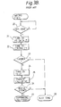
- a preferred embodiment of the cordless telephone apparatus in accordance with the present invention gives priority to originating connection when an originating and a terminating call signal conflict.
- the control section 13 turns on the power switch 17 (step 31, time T1).
- the control section 13 designates, among a plurality of voice channels and control channels assigned to the cordless telephone apparatus, a single control channel (step 32) and then switches the transmitting section 14 and receiving section 15 to the designated channel.
- the carrier sensing circuit 19 checks the designated control channel to see if a carrier exists thereon (step 33).
- the control section 13 turns on the transmission output of the transmitting section 14 (step 34, time T2) and controls the signal generating section 18 to send a terminating call signal to the cordless telephone set 4 via the transmitting section 14 (step 35, times T3 to T9).
- the receiving section 15 receives a terminating response signal after the delivery of the terminating call signal (step 36)
- the control section 13 executes terminating connection (step 37).
- the sequence of steps described so far is the same as in the prior art shown in Fig. 3A.
- control section 13 controls the signal generating section 18 to stop the delivery of the terminating call signal (step 39), sends an originating answer signal to the telephone set 4 (step 40), and executes originating connection (step 41).
- the control section 13 executes a termination NG procedure (step 43).
- the control section 22 detects it (step 50, time T3), turns on the power switches 24 and 25 (step 51, time T4), designates a single control channel (step 52), and tunes the transmitting section 27 and receiving section 21 to the designated channel.
- the carrier sensing circuit 30 checks the designated control channel to see if a carrier exists thereon (step 53).
- the control section 22 turns on the transmitting section 27 (step 54) and controls the signal generating section 29 to send an originating call signal to the connecting unit 3 via the transmitting section 27 (step 55, time T7).
- the control section 22 executes originating connection (step 57).
- step 58 Assume that an identification signal coincident with that of the cordless telephone set 4 has been detected in the terminating call signal which is included in the received carrier (step 58, time T6). Then, even if the output of the carrier sensing circuit 30 is "CARRIER" (step 53, time T5), the control circuit 13 turns on the transmitting section 27 (step 54) and enters into a procedure for sending an originating call signal to the connecting unit 3 (steps 55 to 57).
- control section 22 causes the handset 13 to output a busy tone (step 60) and does not execute originating connection.
- the connecting unit 3 On detecting a call incoming signal, the connecting unit 3 turns on the power switch 17 and then designates a control channel, detects a carrier, turns on the transmitting section 14, and sends a terminating call signal (steps 30 to 35). On the other hand, as the user heard the wire telephone set 2 ringing off-hooks the cordless telephone set 4, the telephone set 4 turns on the power switches 24 and 25 and then designates a control channel and detects a carrier (steps 50 to 53). At the time T5, the connecting unit 3 has already started sending a terminating call signal and, therefore, the cordless telephone set 4 produces "CARRIER".
- the connecting unit 3 receives the originating call signal having the coincident identification code (Y, step 38) and, therefore, stops sending the terminating call signal (step 39), sends an originating answer signal for designating a voice channel of the cordless telephone set 4 (step 40), and tunes its own transmitting and receiving sections 14 and 15 to the designated voice channel (step 41).
- the telephone set 4 On receiving the originating answer signal (Y, step 56), the telephone set 4 switches the transmitting and receiving sections 27 and 21 to the designated voice channel and sends an end-of-switch signal (step 57). On receiving the end-of-switch signal, the connecting unit 3 sends an AF ON signal indicative of the completion of radio connection and thereby sets up a communicable state (step 41). On receiving the AF ON signal, the telephone set 4 is caused into a communicable state (step 57) to allow the user to converse with the other party.
- the illustrative embodiment causes the cordless telephone set 4 to send an originating call signal even in the "CARRIER" condition when it has detected a terminating call signal with a coincident identification signal.
- the connecting unit 3 When the connecting unit 3 has detected an originating call signal while transmitting a terminating call signal, it sends an originating answer signal.
- priority is given to originating connection so as to successfully connect the telephone set 4 and connecting unit 3 to each other.
- An alternative embodiment of the present invention which will be described gives priority to terminating connection in the event when an originating and a terminating call signal conflict.
- the alternative embodiment is also practicable with the circuitry shown in Fig. 2 except for the control systems of the control sections 13 and 22.
- Fig. 7A for describing a terminating connection flow to be executed by the connecting unit 3.
- the control section 13 turns on the power switch 17 and then designates a control channel and tunes the transmitting and receiving sections 14 and 15 to the designated control channel.
- the carrier sensing circuit 19 produces a "NO CARRIER" signal associated with the designated control channel (N, step 70)
- the control section 13 turns on the transmitting section 14 and sends a terminating call signal to the cordless telephone set 4 via the transmitting section 14 by controlling the signal generating section 18 (step 71).
- the control section 13 executes terminating connection (step 73).
- the control section 13 neglects it and transmits the terminating call signal from the signal generating section 18 to the cordless telephone set 4 via the transmitting section 14 (step 71).
- the receiving section 15 receives a terminating response signal (step 72)
- the control section 13 enters into the following termination connection procedure (step 73).
- the control section 13 executes the termination NG procedure (step 75) when it receives an originating call signal with a non-coincident identification signal via the receiving section 19 or when it does not receive a terminating response signal (N, step 72).
- Originating and terminating call connection executed by the cordless telephone set 4 will be described with reference to Fig. 7B.
- the control section 22 detects the off-hook of the hook switch 26 effected by the user of the cordless telephone set 4 (step 80), it turns on the power switches 24 and 25 and then designates a control channel and tunes the receiving and transmitting section 27 to that control channel.
- the output of the carrier sensing circuit 30 is "CARRIER" (Y, step 81) and if it is representative of a terminating call signal with a coincident identification signal (Y, step 82)
- the control section 22 interrupts the originating connection procedure.
- the control section 22 sends a terminating response signal to the terminating call signal to the connecting unit 3 via the transmitting section 27 (step 83) and then starts on the following terminating connection procedure (step 84).
- the carrier sensing circuit 30 has produced a "NO CARRIER" output associated with the designated control channel (N, step 81) after the detection of the off-hook of the hook switch 26 (step 80). Then, the control section 22 turns on the transmitting section 27 and, thereafter, sends an originating call signal from the signal generating section 29 to the connecting unit 3 via the transmitting section 27 (step 85).
- the control section 22 stops sending the originating call signal from the signal generating section 29 (step 88), sends a terminating response signal from the signal generating section 29 via the transmitting section 27 (step 83), and executes the following terminating connection (step 84).
- the alternative embodiment shown and described provides the connecting unit 3 with terminating call signal priority sending means and provides the cordless telephone set 4 with terminating response signal priority sending means, so that terminating connection may be executed prior to originating connection when an originating and a terminating call occur substantially at the same time. This is successful in preventing both of the terminating and originating calls from resulting in loss connection.
Description
- The present invention relates to a cordless telephone apparatus and, more particularly, to a cordless telephone apparatus having a connecting unit connected to a telephone channel and a cordless telephone set connected to the connecting unit by a radio channel, a wire telephone set being also connected to the telephone channel.
- A cordless telephone apparatus has customarily been made up of a connecting unit connected to a telephone channel, or to subscriber line, and a cordless telephone set connected to the connecting unit by a radio channel. After either one of the connecting unit and cordless telephone set has determined that a carrier does not exist on a control channel, i.e., "NO CARRIER", an originating or a terminating call signal is sent over the control channel. Then, only if the other party which has receives the call signal determines that the identification signal of the cordless telephone set and one included in the originating or terminating call signal are coincident, a voice channel between the connecting unit and the telephone set is set up.
- When a wire telephone set is connected in parallel to the telephone channel of the cordless telephone apparatus, an incoming call always causes the bell of the wire telephone set to ring before that of the cordless telephone set. As the user of the cordless telephone set who heard the wire telephone set ringing may off-hook the cordless telephone set before the connecting unit sends a terminating call signal, the cordless telephone set detects no carrier and thus commences a call origination. Consequently, a terminating call signal from the connecting unit and an originating call signal from the cordless telephone set conflict with each other. The conflict often causes both of the originating connection and the terminating connection to fail, resulting in loss connections.
- European patent Application No. 88111411.0, which was published under number 299 515, proposed a cordless telephone apparatus which turns on a transmission output and connects a radio channel when identification signals coincide.
- Features of a cordless telephone unit which is to be described below, by way of example, are that when a terminating and an originating connection request conflict, either one of them is processed prior to the other in order to implement sure connection for communication.
- Particular arrangement to be described below, as an example, a cordless telephone set and a connecting unit of a cordless telephone apparatus have particular means for giving priority to call origination processing when a terminating and an originating call signal conflict, as follows. The connecting unit has means for interrupting, when an originating call signal with a coincident identification signal is detected during the course of transmission of a terminating call signal, the transmission of the terminating call signal and sends an originating answer signal to the telephone set to execute originating connection. The telephone set has means for sensing a carrier on a control channel on detecting off-hook while in a waiting state and, if the result is "NO CARRIER", starts on transmission. Even if the result is "CARRIER", the means starts on transmission when the telephone set has detected a terminating call signal with a coincident identification code, and then sends an originating call signal to the connecting unit. In this construction, the telephone set sends, even in a "CARRIER" condition, an originating call signal when it has detected a terminating call signal with a coincident identification signal, while the connecting unit sends an originating answer signal when it has detected an originating call signal during the course of transmission of a terminating call signal. As a result, an originating call signal and a terminating call signal from the telephone set and the connecting unit, respectively, are prevented from conflicting with each other.
- An alternative embodiment illustrative of the present invention has the following means for giving priority to call termination processing when a terminating and an originating call signal conflict. Specifically, the connecting unit has terminating call signal priority sending means for sending a terminating call signal to the cordless telephone set prior to an originating answer signal sending procedure when, in the event of termination of a call, "CARRIER" is detected on the control channel and an originating call signal with a coincident identification signal is received from the telephone set. The telephone set has terminating call signal priority sending means for sending a terminating response signal prior to an originating connection procedure when, in the event of call origination and during an interval between the off-hook and the reception of an originating answer signal from the connecting unit, "CARRIER" is detected on the control channel and a terminating call signal with a coincident identification signal is received from the connecting unit.
- The following description and drawings disclose, by means of examples, the invention which is characterised in the appended claims, whose terms determine the extent of the protection conferred hereby.
- In the drawings:-
- Fig. 1 is a schematic block diagram showing the connection of a wire telephone set and a cordless telephone unit;
- Fig. 2 is a schematic block diagram showing a connecting unit and a cordless telephone set,
- Figs. 3A and 3B are flowcharts demonstrating terminating connection and originating connection executed by a conventional connecting unit and a conventional cordless telephone set, respectively;
- Fig. 4 is a timing chart representative of the conflict of a terminating call and an originating call occurring in the conventional arrangement;
- Figs. 5A and 5B are flowcharts demonstrating respectively terminating connection and originating connection executed by a connecting unit and a cordless telephone set,
- Fig. 6 is a timing chart representative of the conflict of a terminating call and an originating call particular to the illustrative embodiment; and
- Figs. 7A and 7B are flowcharts showing respectively originating connection and terminating connection executed by a connecting unit and a cordless telephone set representative of an alternative embodiment,
- Referring to Fig. 1 of the drawings, a cordless telephone apparatus embodying the present invention is shown. As shown, a
wire telephone set 2 and a connectingunit 3 of the cordless telephone apparatus are connected in parallel to a public switching telephone network (PSTN) through a telephone subscriber line, or channel, 1. Acordless telephone set 4 included in the cordless telephone apparatus is connected to the connectingunit 3 by aradio channel 5. - The cordless telephone apparatus will be described in more detail with reference to Fig. 2. A shown in Fig. 2, the connecting
unit 3 has ahybrid circuit 11 connected to thetelephone channel 1, a callincoming detection circuit 12 also connected to thetelephone channel 1, acontrol section 13, a transmittingsection 14, areceiving section 15, apower source section 16, apower switch 17, and asignal generating section 18. Thereceiving section 15 includes acarrier sensing circuit 19. Thecontrol section 13 controls the operations of the entire connectingunit 3. The transmittingsection 14 converts a voice signal coming in over thetelephone channel 1 and control signals generated within the connecting unit 3 (e.g., terminating call signal and originating answer signal) into radio signals. Thereceiving section 15 transforms a radio signal received from the cordless telephone set 4 over the radio channel into a wire signal. Thesignal generating section 18 generates the terminating call signal, originating answer signal, etc. Thecarrier sensing circuit 19 detects a received carrier level by comparing it with a predetermined reference level. - The
cordless telephone set 4 has areceiving section 21, acontrol section 22, ahandset 23,power switches hook switch 26, a transmittingsection 27, abattery 28, and asignal generating section 29. Thereceiving section 21 includes acarrier sensing circuit 30. Thereceiving section 21 converts a radio signal received from the connectingunit 3 over the radio channel into a wire signal. Thecontrol section 22 controls the operations of the entirecordless telephone set 4. Thehandset 23 is adapted for the input and output of voice signals. The transmittingsection 27 transforms avoice signal 23 from thehandset 23 and control signals generated within the telephone set 4 (e.g., originating call signal and terminating response signal) into radio signals and transmits them. Thesignal generating section 29 generates an originating call signal, a terminating call signal, etc. The carrier sensing circuit senses a received carrier level by comparing it with a predetermined reference level. When thetelephone set 4 is in a waiting state, thecontrol section 22 thereof turns off the transmission output by controlling the transmittingsection 27 and turns thepower switch 25 on and off, thereby remaining in a battery saving mode. Thehandset 23 and transmittingsection 27 share a single power source for the sake of economy. - The
carrier sensing circuits - To better understand the present invention, the operation of a conventional cordless telephone unit will first be described referring to Figs. 3A and 3B. While the conventional cordless telephone unit is similar in construction to the illustrative embodiment, the former is different from the latter regarding the termination control and origination control which are executed by the
control section 13 of the connectingunit 3 and thecontrol section 22 of thecordless telephone set 4, respectively. - To begin with, terminating connection particular to the conventional cordless telephone unit will be described with reference to Figs. 3A and 4. Assume that the call incoming
detective circuit 12 has detected a terminating call signal in the form of a sinusoidal wave whose frequency is 16 Hz (step 10, time T0) when the connectingunit 3 is in a waiting state. Then, thecontrol section 13 turns on the power switch 17 (step 11, time T2). At the same time, thecontrol section 13 designates, among a plurality of voice channels and control channels assigned to the cordless telephone unit, a single control channel (step 12) and tunes the transmittingsection 14 and receivingsection 15 to the designated channel. Thereafter, thecarrier sensing circuit 19 checks the designated channel to see if a carrier exists thereon (step 13). If thecarrier sensing circuit 19 produces a "NO CARRIER" output, thecontrol section 13 turns on the transmitting section 14 (stop 14, time T3) so as to send to the cordless telephone set 4 a terminating call signal including an identification signal of telephone set 4 (step 15, times T5 to T7). When thecontrol section 13 receives a terminating response signal (step 16) after the transmission of the terminating call signal, it executes a terminating connection procedure (step S17). Assume that the output of thecarrier sensing circuit 19 has not changed to "NO CARRIER" within a predetermined period of time or the receivingsection 15 has not received a terminating call signal within a predetermined period of time after the delivery of the terminating call signal. Then, thecontrol section 13 executes, in place of the terminating connection procedure, a terminating NG procedure such as ringing a bell which is incorporated in the connecting unit 3 (step 18). - The conventional cordless telephone unit executes originating connection, as will be described with reference to Figs. 3B and 4. Assume that the user of the cordless telephone unit has pressed the hook switch (off hook) to originate a call while the telephone set 4 is in a waiting state. Then, the
control section 22 detects the off-hook (step 20, time T1), turns on the power switches 24 and 25 (step 21, time T2), designates a single control channel (step 22), and tunes the transmittingsection 27 and receivingsection 21 to the designated channel. Thereupon, thecarrier sensing circuit 30 checks the designated control channel to see if a carrier exists thereon (step 23). If the resulting output of thecarrier sensing circuit 30 is "NO CARRIER", thecontrol section 22 turns on the transmitting section 27 (step 24, time T3) and controls thesignal generating section 29 to send an originating call signal including the identification signal oftelephone unit 4 to the connecting unit 3 (step 25, times T4 to T6). Afterwards, when the receivingsection 21 receives an originating answer signal (step 26), thecontrol section 22 executes an originating connection procedure (step 27). If the output of thecarrier sensing circuit 30 does not change to "NO CARRIER" within a predetermined period of time or the receivingsection 21 does not receive an originating answer signal (step 26), thecontrol section 22 outputs a busy tone via the receivingsection 21 and handset 13 (step 28). - When the wire telephone set 2 is connected to the
telephone channel 1 to which the connectingunit 3 of the conventional cordless telephone unit is connected, the wire telephone set 2 rings first at all times on receiving an incoming call. Hence, as the user heard the wire telephone set 2 ringing presses thehook switch 26 of the cordless telephone set 4 (off hook), the call terminating operation (Fig. 3A) by the connectingunit 3 and the call originating operation (Fig. 3B) by the cordless telephone set 4 conflict. Specifically, as shown in Fig. 4, the connectingunit 3 sends a terminating call signal at the time T5 while the cordless telephone set 4 sends an originating call signal at the time T4. As a result, the connectingunit 3 and the telephone set 4 conflict and detect a carrier at the same time. Then, it is likely that both of the originating call and the terminating call fall into connection NG and, therefore, loss connection. - A preferred embodiment of the cordless telephone apparatus in accordance with the present invention gives priority to originating connection when an originating and a terminating call signal conflict.
- A reference will be made to Figs. 5A and 6 for describing terminating connection particular to the connecting
unit 3 of the illustrative embodiment. - As shown, assume that the call
incoming detective circuit 12 has detected a terminating call signal (step 30, time T0) while the connectingunit 3 is in a waiting state. Then, thecontrol section 13 turns on the power switch 17 (step 31, time T1). At the same time, thecontrol section 13 designates, among a plurality of voice channels and control channels assigned to the cordless telephone apparatus, a single control channel (step 32) and then switches the transmittingsection 14 and receivingsection 15 to the designated channel. In this condition, thecarrier sensing circuit 19 checks the designated control channel to see if a carrier exists thereon (step 33). If the resulting output of thecarrier detective circuit 19 is "NO CARRIER", thecontrol section 13 turns on the transmission output of the transmitting section 14 (step 34, time T2) and controls thesignal generating section 18 to send a terminating call signal to the cordless telephone set 4 via the transmitting section 14 (step 35, times T3 to T9). When the receivingsection 15 receives a terminating response signal after the delivery of the terminating call signal (step 36), thecontrol section 13 executes terminating connection (step 37). The sequence of steps described so far is the same as in the prior art shown in Fig. 3A. - Assume that the
control section 13 has received via the receivingsection 19 an originating call signal including an identification signal which is coincident with the identification signal assigned to the cordless telephone set 4 which should be connected to the connecting unit 3 (step 38, time T8). Then, thecontrol section 13 controls thesignal generating section 18 to stop the delivery of the terminating call signal (step 39), sends an originating answer signal to the telephone set 4 (step 40), and executes originating connection (step 41). When the output of the carrier sensing circuit 19 (step 33) does not change to "NO CARRIER" within a predetermined period of time or when a terminating call signal is not received within a predetermined period of time after the delivery of the terminating call signal (step 42), thecontrol section 13 executes a termination NG procedure (step 43). - How the cordless telephone set 4 executes originating connection will be described with reference to Figs. 5B and 6.
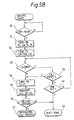
- Assume that the user of the cordless telephone apparatus has pressed the
hook switch 26 to originate a call (off hook) while the cordless telephone set 4 is in a waiting state. Then, thecontrol section 22 detects it (step 50, time T3), turns on the power switches 24 and 25 (step 51, time T4), designates a single control channel (step 52), and tunes the transmittingsection 27 and receivingsection 21 to the designated channel. Subsequently, thecarrier sensing circuit 30 checks the designated control channel to see if a carrier exists thereon (step 53). If the output of thecarrier sensing circuit 30 is "NO CARRIER", thecontrol section 22 turns on the transmitting section 27 (step 54) and controls thesignal generating section 29 to send an originating call signal to the connectingunit 3 via the transmitting section 27 (step 55, time T7). When the receivingsection 21 receives the originating answer signal (step 56), thecontrol section 22 executes originating connection (step 57). The steps described so far are the same as in the prior art shown in Fig. 3B. - Assume that an identification signal coincident with that of the cordless telephone set 4 has been detected in the terminating call signal which is included in the received carrier (
step 58, time T6). Then, even if the output of thecarrier sensing circuit 30 is "CARRIER" (step 53, time T5), thecontrol circuit 13 turns on the transmitting section 27 (step 54) and enters into a procedure for sending an originating call signal to the connecting unit 3 (steps 55 to 57). On the other hand, when the output of thecarrier sensing circuit 30 does not turn to "NO CARRIER" within a predetermined period of time (steps 58 and 59) or when the receivingsection 21 does not receive an originating answer signal within a predetermined period of time (N, step 56), thecontrol section 22 causes thehandset 13 to output a busy tone (step 60) and does not execute originating connection. - The conflict of an originating and a terminating call signal which may occur in the first embodiment and is an issue heretofore discussed will be described with reference to Figs. 5A, 5B and 6.
- On detecting a call incoming signal, the connecting
unit 3 turns on thepower switch 17 and then designates a control channel, detects a carrier, turns on the transmittingsection 14, and sends a terminating call signal (steps 30 to 35). On the other hand, as the user heard the wire telephone set 2 ringing off-hooks thecordless telephone set 4, the telephone set 4 turns on the power switches 24 and 25 and then designates a control channel and detects a carrier (steps 50 to 53). At the time T5, the connectingunit 3 has already started sending a terminating call signal and, therefore, the cordless telephone set 4 produces "CARRIER". However, at the time T6, the terminating call signal having a coincident identification code is received (Y, step 58), so that the cordless telephone set 4 turns on the transmitting section 27 (step 54) and sends an originating call signal (step 55). At the time T8, the connectingunit 3 receives the originating call signal having the coincident identification code (Y, step 38) and, therefore, stops sending the terminating call signal (step 39), sends an originating answer signal for designating a voice channel of the cordless telephone set 4 (step 40), and tunes its own transmitting and receivingsections sections unit 3 sends an AF ON signal indicative of the completion of radio connection and thereby sets up a communicable state (step 41). On receiving the AF ON signal, the telephone set 4 is caused into a communicable state (step 57) to allow the user to converse with the other party. - As stated above, the illustrative embodiment causes the cordless telephone set 4 to send an originating call signal even in the "CARRIER" condition when it has detected a terminating call signal with a coincident identification signal. When the connecting
unit 3 has detected an originating call signal while transmitting a terminating call signal, it sends an originating answer signal. As a result, when the originating call signal from the telephone set 4 and the terminating call signal from the connectingunit 3 conflict, priority is given to originating connection so as to successfully connect the telephone set 4 and connectingunit 3 to each other. - An alternative embodiment of the present invention which will be described gives priority to terminating connection in the event when an originating and a terminating call signal conflict. The alternative embodiment is also practicable with the circuitry shown in Fig. 2 except for the control systems of the
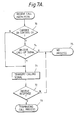
control sections - First, a reference will be made to Fig. 7A for describing a terminating connection flow to be executed by the connecting
unit 3. Assume that the callincoming detective circuit 12 has detected a call incoming signal while in a waiting state. Then, thecontrol section 13 turns on thepower switch 17 and then designates a control channel and tunes the transmitting and receivingsections carrier sensing circuit 19 produces a "NO CARRIER" signal associated with the designated control channel (N, step 70), thecontrol section 13 turns on the transmittingsection 14 and sends a terminating call signal to the cordless telephone set 4 via the transmittingsection 14 by controlling the signal generating section 18 (step 71). Thereafter, when the receivingsection 15 receives a terminating response signal from the telephone set 4 (step 72), thecontrol section 13 executes terminating connection (step 73). - Assume that the output of the
carrier sensing circuit 19 associated with the designated control channel is "CARRIER" (Y, step 70). Then, even if an originating call signal having a coincident identification signal (calling name) has been received (Y, step 74), thecontrol section 13 neglects it and transmits the terminating call signal from thesignal generating section 18 to the cordless telephone set 4 via the transmitting section 14 (step 71). When the receivingsection 15 receives a terminating response signal (step 72), thecontrol section 13 enters into the following termination connection procedure (step 73). - The
control section 13 executes the termination NG procedure (step 75) when it receives an originating call signal with a non-coincident identification signal via the receivingsection 19 or when it does not receive a terminating response signal (N, step 72). - Originating and terminating call connection executed by the cordless telephone set 4 will be described with reference to Fig. 7B. When the
control section 22 detects the off-hook of thehook switch 26 effected by the user of the cordless telephone set 4 (step 80), it turns on the power switches 24 and 25 and then designates a control channel and tunes the receiving and transmittingsection 27 to that control channel. When the output of thecarrier sensing circuit 30 is "CARRIER" (Y, step 81) and if it is representative of a terminating call signal with a coincident identification signal (Y, step 82), thecontrol section 22 interrupts the originating connection procedure. At the same time, thecontrol section 22 sends a terminating response signal to the terminating call signal to the connectingunit 3 via the transmitting section 27 (step 83) and then starts on the following terminating connection procedure (step 84). - Assume that the
carrier sensing circuit 30 has produced a "NO CARRIER" output associated with the designated control channel (N, step 81) after the detection of the off-hook of the hook switch 26 (step 80). Then, thecontrol section 22 turns on the transmittingsection 27 and, thereafter, sends an originating call signal from thesignal generating section 29 to the connectingunit 3 via the transmitting section 27 (step 85). When the receivingsection 21 does not receive an originating answer signal to the originating call signal from the connecting unit 3 (N, step 86) and receives a terminating call signal with a coincident identification signal (Y, step 87), thecontrol section 22 stops sending the originating call signal from the signal generating section 29 (step 88), sends a terminating response signal from thesignal generating section 29 via the transmitting section 27 (step 83), and executes the following terminating connection (step 84). - When a terminating call signal with a non-coincident call number identification signal is received (N, step 82 or N, step 87), neither the originating connection nor the terminating connection is executed and, instead, a busy tone is outputted via the handset 13 (step 89). When a terminating answer signal from the connecting
unit 3 is received (Y, step 86), terminating connection is executed (step 90). - In summary, the alternative embodiment shown and described provides the connecting
unit 3 with terminating call signal priority sending means and provides the cordless telephone set 4 with terminating response signal priority sending means, so that terminating connection may be executed prior to originating connection when an originating and a terminating call occur substantially at the same time. This is successful in preventing both of the terminating and originating calls from resulting in loss connection. - Although the invention has been described with reference to specific embodiments, this description is not meant to be construed in a limiting sense. Various modifications of the disclosed embodiments, as well as other embodiments of the invention, will become apparent to persons skilled in the art upon reference to the description of the invention. It is therefore contemplated that the appended claims will cover any modifications or embodiments as fall within the true scope of the invention.
Claims (12)
- A cordless telephone apparatus including a connecting unit (3) connected to a telephone channel (1), and a cordless telephone set (4) connectable to the connecting unit over a radio channel, said cordless telephone apparatus turning on a transmission output and connecting the radio channel only on confirming that the identification signals of said cordless telephone set (4) and the connecting unit (3) are coincident, characterised in that the transmission output is turned on, on a confirmation of "NO CARRIER" on a control channel, said connecting unit comprising means for interrupting (step 39), when an originating call signal with a coincident identification signal is detected (step 38) during the course of transmission of a terminating call signal, the transmission of said terminating call signal and sending an originating answer signal (step 40) to said cordless telephone set to execute originating connection, said cordless telephone set comprising means (30) for sensing, when off-hook is detected in a waiting state, a carrier on said control channel, turning on the transmission output (27) after "NO CARRIER" has been confirmed, and even in a "CARRIER" state turning on (step 58) the transmission output (27) if a terminating call signal with a coincident identification signal is detected and then transmitting an originating call signal (step 55) to said connecting unit (3).
- A telephone apparatus as claimed in claim 1, wherein said connecting unit (3) and the cordless telephone set (4) are connected to each other by the control channel and a plurality of voice channels.
- A telephone apparatus as claimed in claim 1, wherein a wire telephone set (2) is connected to said telephone channel (1) to which said connecting unit is connected.
- A connecting unit for use in a cordless telephone apparatus as claimed in claim 1 including:
a call incoming detecting circuit (12) for detecting a call incoming signal from a telephone channel (1), a signal generator (18) for generating a terminating call signal and an originating answer signal, a receiver section (15) for receiving an originating call signal and a terminating response signal in said use from a cordless telephone set (4) over a designated control channel, a carrier sensing circuit (19) included in said receiver section (15), a transmitter section (14), and a control section (13) for designating a control channel when the call incoming detecting circuit (12) detects a call incoming signal, wherein the control section (13) controls transmission of a terminating call signal from said signal generator (18), section means via said transmitting section (14) when said carrier sensing circuit (19) produces a "NO CARRIER" output indicating that a carrier does not exist on said designated control channel, and wherein the control section (13) interrupts, when an originating call signal with a coincident identification signal is received (step 38) from said receiving section (15) while the terminating call signal is transmitted (step 35), the transmission of said terminating call signal, controls said signal generating section (14) to send (step 40) an originating answer signal to said originating call signal to said cordless telephone set (4) via said transmitting section means, and executes (step 41) originating connection. - A cordless telephone set for use in a cordless telephone apparatus as claimed in claim 1, including:
a signal generating section (29) for generating an originating call signal and a terminating response signal, a receiving section (21) for receiving a terminating call signal and an originating answer signal from a connecting unit (3) of said cordless telephone apparatus in said use, a carrier sensing circuit (30) included in said receiving section means, a transmitting section (27), a handset (23), and a control section (22) for designating a control channel on on-hook (26) of said handset (23) and, when said carrier sensing circuit (30) produces a "NO CARRIER" output indicating that a carrier does not exist on said designated control channel, sending an originating call signal (steps 54, 55) via the transmitting section (27) and executing originating connection (step 57), said control section comprising originating connection priority processing means for controlling (step 58), even when said carrier sensing circuit means produces a "CARRIER" output indicating that a carrier exists on said designated control channel, said signal generating section (29) to send (step 57) an originating call signal to said connecting unit via said transmitting section means if a terminating call signal with a coincident identification signal is received from said receiving section (21). - A cordless telephone apparatus including:
a connecting unit (3) connected to a telephone channel (1), and a cordless telephone set (4) connectable to the connecting unit over a radio channel, said cordless telephone set turning on a transmission output and connecting said radio channel only on confirming that the identification signals of said cordless telephone set (4) and the connecting unit (3) are coincident,
characterised
in that the transmission output is turned on, on a confirmation of "NO CARRIER" on a control channel, said connecting unit (3) including terminating call signal priority sending means for sending a terminating call signal to said cordless telephone set (4) prior to the execution of an originating answer signal transmission procedure when, in the event of call termination, a "CARRIER" condition of said control channel is detected (step 70, Y) and an originating call signal with a coincident identification signal is received (step 74) from said cordless telephone set (4), said cordless telephone set (4) including terminating response signal priority sending means for sending (step 83) a terminating response signal prior to the execution of an originating connection procedure (step 90) when, in the event call origination and during an interval between off-hook (step 80) and reception (step 86) of an originating answer signal from said connecting unit, a "CARRIER" condition is detected (step 82) and a terminating call signal with a coincident identification signal is received from said connecting unit (3). - A telephone apparatus as claimed in claim 6, wherein said terminating call signal priority sending means comprises:
a signal generating section for generating the terminating call signal and the originating answer signal, a receiving section for receiving an originating call signal with a coincident identification signal and the terminating response signal from said cordless telephone set, a carrier sensing circuit included in said receiving section, and a control section for sending the terminating call signal from said first signal generating section via said first transmitting section when said carrier sensing circuit produces a "CARRIER" output associated with said control channel and said receiving section receives the originating call signal with a coincident identification signal;. - A telephone apparatus as claimed in claim 6, wherein said terminating response signal priority sending means comprises:
a signal generating section for generating the originating call signal and the terminating response signal, a receiving section for receiving a terminating call signal with a coincident identification signal and the originating answer signal from said connecting unit, a transmitting section, and a control section for sending the terminating response signal from said second signal generating section via said transmitting section when, in the event when a call is originated on said cordless telephone set and during an interval between off-hook and reception of the originating answer signal by said receiving section. - A telephone apparatus as claimed in claim 6, wherein said connecting unit and said cordless telephone set are connected by said control channel and a plurality of voice channels.
- A telephone apparatus as claimed in claim 6, wherein a wire telephone set is connected to the telephone channel to which said connecting unit is connected.
- A connecting unit for use in a cordless telephone apparatus as claimed in claim 6, a call incoming detecting circuit (12) for detecting a call incoming signal from a telephone channel (1), a signal generating section (18) for generating a terminating call signal and an originating answer signal, a receiving section (15) for receiving an originating call signal and a terminating response signal from a cordless telephone set (4) over a designated control channel, a carrier sensing circuit (19) included in said receiving section (15), a transmitting section (14), and a control section (13) for designating a control channel when said call incoming detecting circuit (12) detects a call incoming signal and, when said carrier sensing circuit (19) produces a "NO CARRIER" output indicating that a carrier does not exist on said designated control channel, sending a terminating call signal from said signal generating section (18) via said transmitting section (14), said control section (13) comprising terminating call priority processing means for sending, even when said carrier sensing circuit (19) produces a "CARRIER" output, the terminating call signal from said signal generating section means via said transmitting section means if an originating call signal with a coincident identification signal is received by said receiving section (15) and, thereafter, executing terminating connection when a terminating response signal is received via said receiving section means.
- A cordless telephone set for use in a cordless telephone apparatus, as claimed in claim 6, including:
a signal generating section (29) for generating an originating call signal and a terminating response signal, a receiving section (21) for receiving a terminating call signal and an originating answer signal from a connecting unit (3), a carrier sensing circuit (30) included in said receiving section (21), a transmitting section (27), a handset (23), and a control section (22) for designating a control channel on off-hook of the handset, sending an originating call signal via the transmitting section when the carrier sensing circuit (30) produces a "NO CARRIER" output indicating that a carrier does not exist, and executing originating connection when the receiving section (21) receives an originating answer signal, the control section (22) including terminating call priority processing means for sending (step 83) a terminating response signal from said signal generating section (29) via the transmitting section (27) when, during an interval between off-hook of the handset (23) and reception of the originating answer signal, the carrier sensing circuit (30) produces a "CARRIER" output associated with the control channel and the receiving section (21) receives a terminating call signal with a coincident identification signal.
Applications Claiming Priority (4)
| Application Number | Priority Date | Filing Date | Title |
|---|---|---|---|
| JP283846/89 | 1989-10-31 | ||
| JP1283846A JP2936602B2 (en) | 1989-10-31 | 1989-10-31 | Cordless telephone equipment |
| JP304305/89 | 1989-11-22 | ||
| JP1304305A JP2515897B2 (en) | 1989-11-22 | 1989-11-22 | Cordless telephone equipment |
Publications (3)
| Publication Number | Publication Date |
|---|---|
| EP0426451A2 EP0426451A2 (en) | 1991-05-08 |
| EP0426451A3 EP0426451A3 (en) | 1992-12-16 |
| EP0426451B1 true EP0426451B1 (en) | 1996-10-09 |
Family
ID=26555224
Family Applications (1)
| Application Number | Title | Priority Date | Filing Date |
|---|---|---|---|
| EP90311924A Expired - Lifetime EP0426451B1 (en) | 1989-10-31 | 1990-10-31 | Cordless telephone apparatus |
Country Status (7)
| Country | Link |
|---|---|
| US (1) | US5123042A (en) |
| EP (1) | EP0426451B1 (en) |
| KR (1) | KR940000849B1 (en) |
| AU (1) | AU6573790A (en) |
| CA (1) | CA2028775C (en) |
| DE (1) | DE69028830T2 (en) |
| HK (1) | HK85297A (en) |
Families Citing this family (10)
| Publication number | Priority date | Publication date | Assignee | Title |
|---|---|---|---|---|
| JPH04154331A (en) * | 1990-10-18 | 1992-05-27 | Fujitsu Ltd | Call collision preventing system at time of outgoing/ incoming of isdn network |
| DE9207008U1 (en) * | 1992-05-23 | 1993-09-23 | Emmerich Christoph Gmbh Co Kg | WIRELESS TELECOMMUNICATION TERMINAL |
| JPH0746299A (en) * | 1993-07-31 | 1995-02-14 | Nec Corp | Radio telephone set |
| FI98182C (en) * | 1994-04-27 | 1997-04-25 | Nokia Telecommunications Oy | Method for handling the collision between an outgoing and an oncoming call, a subscriber device and a subscriber network element |
| EP0680188A2 (en) * | 1994-04-28 | 1995-11-02 | Uniden America Corporation | Cordless telephone adapted for use with a corded digital telephone |
| JP3227318B2 (en) * | 1994-11-01 | 2001-11-12 | キヤノン株式会社 | Wireless telephone equipment |
| DE19835395C2 (en) * | 1998-08-05 | 2000-06-29 | Siemens Ag | Collision handling when establishing a connection between a handset and a base station |
| CN101155389B (en) * | 2006-09-27 | 2010-09-22 | 大唐移动通信设备有限公司 | Method and device for processing call collision |
| CN101877747B (en) * | 2010-06-28 | 2015-09-16 | 中兴通讯股份有限公司 | The method of avoiding pseudo-busy and terminal |
| CN105657199A (en) * | 2016-02-22 | 2016-06-08 | 北京小米移动软件有限公司 | Method and device for establishing talking connection and switching equipment |
Family Cites Families (5)
| Publication number | Priority date | Publication date | Assignee | Title |
|---|---|---|---|---|
| JPS6069924A (en) * | 1983-09-26 | 1985-04-20 | Nec Corp | Ringing signal transmitting system |
| JP2557892B2 (en) * | 1987-07-15 | 1996-11-27 | 日本電信電話株式会社 | Incoming and outgoing call control method for mobile communication system |
| JP2615635B2 (en) * | 1987-07-16 | 1997-06-04 | 日本電気株式会社 | How to connect a cordless telephone device |
| JPH01149537A (en) * | 1987-12-07 | 1989-06-12 | Nippon Telegr & Teleph Corp <Ntt> | System for controlling radio channel access |
| JPH02199933A (en) * | 1989-01-27 | 1990-08-08 | Victor Co Of Japan Ltd | Method for deciding priority for outgoing/incoming call |
-
1990
- 1990-10-29 CA CA002028775A patent/CA2028775C/en not_active Expired - Fee Related
- 1990-10-30 US US07/605,500 patent/US5123042A/en not_active Expired - Lifetime
- 1990-10-31 KR KR1019900017535A patent/KR940000849B1/en not_active IP Right Cessation
- 1990-10-31 AU AU65737/90A patent/AU6573790A/en not_active Abandoned
- 1990-10-31 DE DE69028830T patent/DE69028830T2/en not_active Expired - Lifetime
- 1990-10-31 EP EP90311924A patent/EP0426451B1/en not_active Expired - Lifetime
-
1997
- 1997-06-19 HK HK85297A patent/HK85297A/en not_active IP Right Cessation
Also Published As
| Publication number | Publication date |
|---|---|
| KR940000849B1 (en) | 1994-02-02 |
| HK85297A (en) | 1997-06-27 |
| US5123042A (en) | 1992-06-16 |
| AU6573790A (en) | 1991-05-09 |
| EP0426451A2 (en) | 1991-05-08 |
| DE69028830D1 (en) | 1996-11-14 |
| CA2028775C (en) | 1994-10-04 |
| EP0426451A3 (en) | 1992-12-16 |
| DE69028830T2 (en) | 1997-04-10 |
| KR910008993A (en) | 1991-05-31 |
| CA2028775A1 (en) | 1991-05-01 |
Similar Documents
| Publication | Publication Date | Title |
|---|---|---|
| EP0631417B1 (en) | Radio telephone system control apparatus and method | |
| US7139585B2 (en) | Wireless communication apparatus and system | |
| EP0426451B1 (en) | Cordless telephone apparatus | |
| WO1995029563A2 (en) | Method for handling collision of calls | |
| EP0363492B1 (en) | Radio communication system and its control method | |
| KR19990086215A (en) | Multiple Ring Tone Service Method in Electronic Switching System | |
| AU658539B2 (en) | Cordless telephone apparatus | |
| EP0331531B1 (en) | Telephone apparatus and a method of controlling same | |
| US5038373A (en) | Process for determining whether a subscriber is the calling or the called party | |
| JP2923195B2 (en) | Digital cordless telephone | |
| JP3420800B2 (en) | Cordless PBX | |
| KR100277063B1 (en) | Private Line Re-Incoming Method of Private Switching System | |
| JP2563637B2 (en) | Automatic redial control method for information communication device | |
| JPH01259659A (en) | Dial-in telephone set | |
| JPS63248271A (en) | Communication equipment | |
| JP3013434B2 (en) | Cordless telephone | |
| JP3112752B2 (en) | How to connect a cordless phone extension | |
| JPH02220522A (en) | Multi-channel access method | |
| JPH06113354A (en) | Telephone set | |
| JP2000023259A (en) | Communication device | |
| JPS60224362A (en) | Switching controller of automatic exchange | |
| JPH04252641A (en) | Cellular telephone set capable of facsimile reception | |
| JPS62225054A (en) | Telephone set with selective incoming notice function | |
| JPH03187532A (en) | Cordless telephone set | |
| JPH03162143A (en) | Subscriber's terminal control circuit |
Legal Events
| Date | Code | Title | Description |
|---|---|---|---|
| PUAI | Public reference made under article 153(3) epc to a published international application that has entered the european phase |
Free format text: ORIGINAL CODE: 0009012 |
|
| 17P | Request for examination filed |
Effective date: 19901123 |
|
| AK | Designated contracting states |
Kind code of ref document: A2 Designated state(s): DE FR GB NL |
|
| PUAL | Search report despatched |
Free format text: ORIGINAL CODE: 0009013 |
|
| AK | Designated contracting states |
Kind code of ref document: A3 Designated state(s): DE FR GB NL |
|
| 17Q | First examination report despatched |
Effective date: 19950412 |
|
| GRAH | Despatch of communication of intention to grant a patent |
Free format text: ORIGINAL CODE: EPIDOS IGRA |
|
| GRAH | Despatch of communication of intention to grant a patent |
Free format text: ORIGINAL CODE: EPIDOS IGRA |
|
| GRAH | Despatch of communication of intention to grant a patent |
Free format text: ORIGINAL CODE: EPIDOS IGRA |
|
| GRAA | (expected) grant |
Free format text: ORIGINAL CODE: 0009210 |
|
| AK | Designated contracting states |
Kind code of ref document: B1 Designated state(s): DE FR GB NL |
|
| REF | Corresponds to: |
Ref document number: 69028830 Country of ref document: DE Date of ref document: 19961114 |
|
| ET | Fr: translation filed | ||
| PLBE | No opposition filed within time limit |
Free format text: ORIGINAL CODE: 0009261 |
|
| STAA | Information on the status of an ep patent application or granted ep patent |
Free format text: STATUS: NO OPPOSITION FILED WITHIN TIME LIMIT |
|
| 26N | No opposition filed | ||
| PGFP | Annual fee paid to national office [announced via postgrant information from national office to epo] |
Ref country code: NL Payment date: 19971031 Year of fee payment: 8 |
|
| PG25 | Lapsed in a contracting state [announced via postgrant information from national office to epo] |
Ref country code: NL Free format text: LAPSE BECAUSE OF NON-PAYMENT OF DUE FEES Effective date: 19990501 |
|
| NLV4 | Nl: lapsed or anulled due to non-payment of the annual fee |
Effective date: 19990501 |
|
| REG | Reference to a national code |
Ref country code: GB Ref legal event code: IF02 |
|
| PGFP | Annual fee paid to national office [announced via postgrant information from national office to epo] |
Ref country code: DE Payment date: 20091029 Year of fee payment: 20 |
|
| PGFP | Annual fee paid to national office [announced via postgrant information from national office to epo] |
Ref country code: FR Payment date: 20091029 Year of fee payment: 20 Ref country code: GB Payment date: 20091028 Year of fee payment: 20 |
|
| REG | Reference to a national code |
Ref country code: GB Ref legal event code: PE20 Expiry date: 20101030 |
|
| PG25 | Lapsed in a contracting state [announced via postgrant information from national office to epo] |
Ref country code: GB Free format text: LAPSE BECAUSE OF EXPIRATION OF PROTECTION Effective date: 20101030 |
|
| PG25 | Lapsed in a contracting state [announced via postgrant information from national office to epo] |
Ref country code: DE Free format text: LAPSE BECAUSE OF EXPIRATION OF PROTECTION Effective date: 20101031 |