EP0426127A1 - Viscous liquid processor - Google Patents
Viscous liquid processor Download PDFInfo
- Publication number
- EP0426127A1 EP0426127A1 EP90120831A EP90120831A EP0426127A1 EP 0426127 A1 EP0426127 A1 EP 0426127A1 EP 90120831 A EP90120831 A EP 90120831A EP 90120831 A EP90120831 A EP 90120831A EP 0426127 A1 EP0426127 A1 EP 0426127A1
- Authority
- EP
- European Patent Office
- Prior art keywords
- blade
- agitator
- viscous liquid
- blade members
- shafts
- Prior art date
- Legal status (The legal status is an assumption and is not a legal conclusion. Google has not performed a legal analysis and makes no representation as to the accuracy of the status listed.)
- Granted
Links
Images


Classifications
-
- B—PERFORMING OPERATIONS; TRANSPORTING
- B01—PHYSICAL OR CHEMICAL PROCESSES OR APPARATUS IN GENERAL
- B01F—MIXING, e.g. DISSOLVING, EMULSIFYING OR DISPERSING
- B01F27/00—Mixers with rotary stirring devices in fixed receptacles; Kneaders
- B01F27/60—Mixers with rotary stirring devices in fixed receptacles; Kneaders with stirrers rotating about a horizontal or inclined axis
-
- B—PERFORMING OPERATIONS; TRANSPORTING
- B01—PHYSICAL OR CHEMICAL PROCESSES OR APPARATUS IN GENERAL
- B01F—MIXING, e.g. DISSOLVING, EMULSIFYING OR DISPERSING
- B01F27/00—Mixers with rotary stirring devices in fixed receptacles; Kneaders
- B01F27/05—Stirrers
- B01F27/11—Stirrers characterised by the configuration of the stirrers
- B01F27/115—Stirrers characterised by the configuration of the stirrers comprising discs or disc-like elements essentially perpendicular to the stirrer shaft axis
-
- B—PERFORMING OPERATIONS; TRANSPORTING
- B01—PHYSICAL OR CHEMICAL PROCESSES OR APPARATUS IN GENERAL
- B01F—MIXING, e.g. DISSOLVING, EMULSIFYING OR DISPERSING
- B01F27/00—Mixers with rotary stirring devices in fixed receptacles; Kneaders
- B01F27/60—Mixers with rotary stirring devices in fixed receptacles; Kneaders with stirrers rotating about a horizontal or inclined axis
- B01F27/70—Mixers with rotary stirring devices in fixed receptacles; Kneaders with stirrers rotating about a horizontal or inclined axis with paddles, blades or arms
- B01F27/701—Mixers with rotary stirring devices in fixed receptacles; Kneaders with stirrers rotating about a horizontal or inclined axis with paddles, blades or arms comprising two or more shafts, e.g. in consecutive mixing chambers
- B01F27/702—Mixers with rotary stirring devices in fixed receptacles; Kneaders with stirrers rotating about a horizontal or inclined axis with paddles, blades or arms comprising two or more shafts, e.g. in consecutive mixing chambers with intermeshing paddles
-
- B—PERFORMING OPERATIONS; TRANSPORTING
- B01—PHYSICAL OR CHEMICAL PROCESSES OR APPARATUS IN GENERAL
- B01F—MIXING, e.g. DISSOLVING, EMULSIFYING OR DISPERSING
- B01F27/00—Mixers with rotary stirring devices in fixed receptacles; Kneaders
- B01F27/60—Mixers with rotary stirring devices in fixed receptacles; Kneaders with stirrers rotating about a horizontal or inclined axis
- B01F27/73—Mixers with rotary stirring devices in fixed receptacles; Kneaders with stirrers rotating about a horizontal or inclined axis with rotary discs
- B01F27/731—Mixers with rotary stirring devices in fixed receptacles; Kneaders with stirrers rotating about a horizontal or inclined axis with rotary discs with two or more parallel shafts provided with perpendicularly mounted discs, e.g. lens shaped, one against the other on each shaft and in circumferential contact with the discs on the other shafts, e.g. for cleaning
Definitions
- the present invention relates to a viscous liquid processor and, more particularly, to a viscous liquid processor which includes two horizontal shafts.
- viscous liquid processors of this kind are roughly classified into a continuous type and a batch type.
- a horizontal viscous liquid processor of the continuous type is structured in such a manner that a material to be processed is supplied from an inlet provided on one longitudinal end of a casing, moves toward an outlet provided on the other longitudinal end (making so-called piston flows) while the degree of reaction or the like is increased, and is discharged from the outlet after a desired process has been completed (see Japanese Patent Examined Publication No. 47-27179, Japanese Utility Model Examined Publication Nos. 51-45559 and 54-5805, Japanese Patent Examined Publication Nos. 61-59173 and 62-50179, and the like). Consequently, the viscous liquid processor of this continuous type has a characteristic that the degree of reaction varies in accordance with the position of the flowing material in the course from the inlet to the outlet.
- a horizontal viscous liquid processor of the batch type is structured in such a manner that one dose of a material to be processed, which has been calculated previously, is fed into a casing, and discharged to the outside after a desired process has been completed, another dose of the material being fed into the casing anew (see Japanese Patent Unexamined Publication No. 49-73759 and the like). Therefore, the viscous liquid processor of this batch type has a characteristic that the degree of reaction varies in accordance with the length of processing time, so that it will be preferred that the material at any poosition in the casing can be simultaneously reacted uniformly in a certain length of processing time.
- a viscous liquid processor requires such functions as uniform shearing and agitation of viscous liquid, circulation or delivery of the liquid in one direction, cooperative scraping of the liquid by agitator blades (self-cleaning), replacement of the liquid surface, and the like.
- these functions especially the shearing/agitation function and the liquid delivering function can be simultaneously effected by means of disk-like agitator blades having a structure as simple as possible.
- a viscous liquid processor comprising a horizontal casing which includes side walls on both longitudinal ends thereof, two shafts extending in parallel within the casing along its longitudinal direction and rotatably supported between the side walls, and a plurality of agitator blades fixed on each of the shafts and spaced along its longitudinal direction so that the blades on one shaft enter the spaces between the blades on the other shaft, the casing having a bottom portion corresponding to the tracks of the outer peripheral ends of the agitator blades, wherein each of the agitator blades is generally formed in a thick disk-like configuration having a plurality of thick blade members, such a thick blade member having a parallelogrammic cross section.
- This embodiment is a batch-type viscous liquid processor including two horizontal shafts for agitating viscous liquid of high-molecular polymer or the like for the purpose of a process such as polycondensation, bulk polymerization, solution polymerization, gas-liquid reaction and monomer degradation.
- reference numeral 1 denotes a casing which has a bottom portion corresponding to the tracks of outer peripheral ends of agitator blades which will be explained later. At the center of this bottom portion, a rib 1a is formed along the longitudinal direction of the casing 1.
- a low-speed shaft 2 and a high-speed shaft 3 extending in parallel are provided horizontally between and through side walls 1b on both longitudinal ends of the casing 1, and the shafts 2 and 3 are rotated in opposite directions to each other, as indicated by arrows p and q, to agitate the liquid to be processed between these shafts from the upper side.
- the shafts 2, 3 are provided with the agitator blades.
- the casing 1 can be sealed with a lid (not shown) in order to perform a reaction process in a vacuum condition or a pressurized condition of reaction gas.
- a low-speed agitator blade 4 is of a shape as shown in Fig. 4. An odd-number (e.g., five) of such blades at different phases are securely fixed on the low-speed shaft 2 so as to form a tandem pattern.
- Each of the low-speed agitator blades 4 is constituted of a plurality of (e.g., four) radially sectorial blade members 5 which are made by machining the intermediate portions cut away from a thick disk at the same intervals.
- a jacket through which a thermal medium flows is formed on the inside of each of the sectorial blade members 5 if necessary. As illustrated in Fig.
- the cross section of the sectorial blade member 5 is formed to be a parallelogram so that the leading end of the blade member as viewed in a direction of rotation of the low-speed agitator blade 4 defines an acute angle, and that the opposite end of the same end surface as the leading end defines an obtuse angle.
- the acute-angled end serves as a shearing edge 5a, and its inclined surface has a liquid delivering function to an, extent of a thickness (h) thereof.
- the low-speed agitator blades 4 are each securely fixed on the low-speed shaft 2 through a boss 6.
- scraper rod 7 is fastened on the trailing outer peripheral end of each sectorial blade member 5 of the low-speed agitator blade 4 as viewed in the direction of rotation, and the other end of the scraper rod 7 is fastened on the leading outer peripheral end of each sectorial blade member 5 of the adjacent agitator blade 4.
- scraper rods 7 are located in a continuous spiral pattern.
- each of the high-speed agitator blades 8 is constituted of a plurality of (e.g., two) wide sectorial blade members 10 (Fig. 5), which are substantially the same as the above-mentioned sectorial blade members 5, formed by machining the intermediate portions cut away from a thick disk, and each of the high-speed agitator blades 9 is constituted a plurality of (e.g., two) small blade members 11 (Fig. 6) having a substantially rectangular shape which are formed by further machining the sectorial blade members.
- the agitator blades 8, 9 are each securely fixed on the high-speed shaft 3 through a boss 13a in such a manner that the blade members 10, 11 are located at phases which are deviated from each other at an angle of 90°C.
- a jacket through whcih a thermal medium flows is formed on the inside of each of the blade members 10, 11 if necessary.
- the cross section of the blade member 10, 11 is formed to be a parallelogram so that the leading end of the blade member as viewed in a direction of rotation of the high-speed agitator blade 8, 9 defines an acute angle, and that the opposite end of the same end surface as the leading end defines an obtuse angle in the same manner as the above-described sectorial blade member 5 for low-speed agitation.
- Side surfaces of these blade members 10, 11 are inclined in a direction reverse to a direction of inclination of the inclined surfaces of the sectorial blade member 5 of the low-speed agitator blade 4.
- scraper rod 12 is fastened on the trailing outer peripheral end of each small blade member 11 of the high-speed agitator blade 9 as viewed in the direction of rotation, and the other end of the scraper rod 12 is fastened on the trailing outer peripheral end of each sectorial blade member 10 of the adjacent agitator blade 8 as viewed in the direction of rotation, while no scraper rod is provided between a sectorial blade member 10 and a small blade member 11 which are adjacent to each other with the above-mentioned low-speed agitator blade 4 interposed therebetween.
- scraper rods 12 are located in a discontinuous spiral pattern whose lead has the same direction as the lead of the spiral pattern formed by the scraper rods 7 of the low-speed shaft 2.
- the sectorial blade members 5 of the low-speed agitator blades 4 are located between such unconnected blade members 10 and 11.
- gate-like agitators formed of the blade members 10, 11 of the high-speed agitator blades 8, 9 and the scraper rods 12 are relatively rotatably provided between the sectorial blade members 5 of two adjacent low-speed agitator blades 4. The condition of these blade members which are rotated across each other when they are viewed from the side wall 1b is illustrated in an area A of Fig. 2.
- each agitator blade of the high-speed shaft 3 has two blade members or more, and that each agitator blade of the low-speed shaft 2 has an integer times as many blade members as the agitator blade of the high-speed shaft 3, with the rotational ratio being set to be an inverse number of the number of the blade members.
- the sectorial blade members 5 of the low-speed agitator blades 4 and the blade members 10, 11 of the high-speed agitator blades 8, 9 together with the scraper rods 7, 12 are relatively rotated, with the blade members on one shaft entering the spaces defined by the blade members on the other shaft in a region between the shafts.
- the viscous liquid is circulated within the casing 1 in a single direction indicated by arrows a, b′, c, b of Fig. 1 under the influence of the liquid delivering functions of the respective inclined surfaces of the blade members 5, 10, 11 in directions indicasted by the arrows a, c.
- the viscous liquid since portions of the viscous liquid which are adhered on the inner peripheral surfaces of the casing 1 are affected by the liquid delivering function while they are scraped for self-cleaning by means of the scraper rods 7, 12 which are located in the spiral patterns having the identical lead, the above-described circulation of the liquid is promoted. Further, when these scraper rods 7, 12 leave the viscous liquid and raise some of the liquid, hanging thin films of the liquid are formed, and consequently, the gas-liquid contact face can be enlarged to improve the efficiency of deaeration.
- Diameter of a disk for an agitator blade 134 mm Size of a casing: 236 mmW x 168 mmH x 612 mmL Liquid quantity: 5.6 l Reaction temperature: 330°C max Viscous liquid: A polyester resin in an intermediate state to be further polymerized and collected as a highly polymerized resin.
- Figs. 11 and 12 illustrate the second embodiment, and the same component parts as those of the first embodiment are denoted by the same reference numerals in these drawings, explanation of such component parts being omitted except for the differences.
- an inlet is formed on one of the side walls 1b of the casing 1 (left in Fig. 11), and an outlet is formed on the other (right in Fig. 11), so that highly viscous liquid supplied from the inlet is processed while it is continuously delivered in a direction indicated by arrows a′ in the drawing, and is discharged from the outlet.
- the low-speed shaft 2 is provided with low-speed agitator blades 4A each including sectorial blade members 5A which are substantially the same as the low-speed agitator blades 4 of the first embodiment described above, and the high-speed shaft 3 is provided with high-speed agitator blades 14 in a tandem pattern each including sectorial blade members 10A similar to the sectorial blade members 10 of the first embodiment shown in Fig. 5, with the inclined surfaces of the sectorial blade members 5A of the low-speed agitator blades 4A being inclined in the same direction as the inclined surfaces of the sectorial blade members 10A of the high-speed agitator blades 14.
- scraper rods 15 are fastened on the outer peripheral ends of the sectorial blade members 5A of the low-speed agitator blades 4A so as to form a continuous spiral pattern in the same manner as the first embodiment.
- each of the high-speed agitator blades 14 is securely fixed on the high-speed shaft 3 at a phase deviated from a phase of the adjacent agitator blade at an angle of 90°C, and one end of a scraper rod 16 is fastened on the leading outer peripheral end of each sectorial blade member 10A of the high-speed agitator blade 14 as viewed in a direction of rotation, while the other end of the scraper rod 16 is fastened on the leading outer peripheral end of each sectorial blade member 10A of the adjacent agitator blade 14, such scraper rods 12 being located in a discontinuous spiral pattern.
- the viscous liquid supplied from the inlet will be continuously agitated and stirred, traveling in the direction of the arrows a toward the outlet.
- each low-speed agitator blade has four sectorial blade members 5, 5A, and each high-speed agitator blade has two blade members 10, 11, 10A.
- the invention will not exclude other combinations of the numbers of these blade members if they meet a ratio 2:1.
- each low-speed agitataor blade may have six blade members, and each high-speed agitator blade may have three blade members.
- the low-speed shaft 2 and the high-speed shaft 3 extending in parallel are rotated in such a manner that the agitator blades on both shafts will agitate the liquid between these shafts from the upper side in the above embodiments.
- the low-speed shaft 2 and the high-speed shaft 3 may be rotated the other way round to cause the agitator blades to agitate the liquid between these shafts from the lower side.
- the agitator blades on both shafts are rotated to agitate the viscous liquid between the two shafts from the upper or lower side, the viscous liquid between the shafts is pressed against the casing.
- Each of the inclined surfaces of the sectorial blade members made of machined disks serves to deliver the liquid to an extent of the thickness thereof, and the opposite inclined surface draws the liquid due to the negative pressure generated thereon.
- each of the agitator blades is thick, so that a jacket for thermal treatment can be formed within the agitator blade.
- each of the blade members has a cross section of a parallelogram, the surfaces of the blade member are smooth and flat, thereby preventing the viscous liquid from adhering to the blade surfaces, while enabling effective scraping by the scraper rods.
Abstract
Description
- The present invention relates to a viscous liquid processor and, more particularly, to a viscous liquid processor which includes two horizontal shafts.
- In general, viscous liquid processors of this kind are roughly classified into a continuous type and a batch type. A horizontal viscous liquid processor of the continuous type is structured in such a manner that a material to be processed is supplied from an inlet provided on one longitudinal end of a casing, moves toward an outlet provided on the other longitudinal end (making so-called piston flows) while the degree of reaction or the like is increased, and is discharged from the outlet after a desired process has been completed (see Japanese Patent Examined Publication No. 47-27179, Japanese Utility Model Examined Publication Nos. 51-45559 and 54-5805, Japanese Patent Examined Publication Nos. 61-59173 and 62-50179, and the like). Consequently, the viscous liquid processor of this continuous type has a characteristic that the degree of reaction varies in accordance with the position of the flowing material in the course from the inlet to the outlet.
- On the other hand, a horizontal viscous liquid processor of the batch type is structured in such a manner that one dose of a material to be processed, which has been calculated previously, is fed into a casing, and discharged to the outside after a desired process has been completed, another dose of the material being fed into the casing anew (see Japanese Patent Unexamined Publication No. 49-73759 and the like). Therefore, the viscous liquid processor of this batch type has a characteristic that the degree of reaction varies in accordance with the length of processing time, so that it will be preferred that the material at any poosition in the casing can be simultaneously reacted uniformly in a certain length of processing time.
- Whether it is of the continuous type or of the batch type, a viscous liquid processor requires such functions as uniform shearing and agitation of viscous liquid, circulation or delivery of the liquid in one direction, cooperative scraping of the liquid by agitator blades (self-cleaning), replacement of the liquid surface, and the like. However, there has conventionally been no viscous liquid processor in which these functions, especially the shearing/agitation function and the liquid delivering function can be simultaneously effected by means of disk-like agitator blades having a structure as simple as possible.
- The present invention has been accomplished to solve the problems of the conventional techniques. It can be summarized as follows: a viscous liquid processor comprising a horizontal casing which includes side walls on both longitudinal ends thereof, two shafts extending in parallel within the casing along its longitudinal direction and rotatably supported between the side walls, and a plurality of agitator blades fixed on each of the shafts and spaced along its longitudinal direction so that the blades on one shaft enter the spaces between the blades on the other shaft, the casing having a bottom portion corresponding to the tracks of the outer peripheral ends of the agitator blades, wherein each of the agitator blades is generally formed in a thick disk-like configuration having a plurality of thick blade members, such a thick blade member having a parallelogrammic cross section.
-
- Fig. 1 is a plan view showing a first embodiment of the present invention;
- Fig. 2 is a vertical cross-sectional view of the first embodiment taken along a line II-II of Fig. 1;
- Fig. 3 is schematic views showing agitator blades of the first embodiment;
- Fig. 4 is a perspective view of a low-speed agitator blade of the first embodiment;
- Figs. 5 and 6 are perspective views showing two kinds of high-speed agitator blades of the first embodiment;
- Figs. 7 to 9 are views illustrative of functions of blade members of the agitator blades shown in Figs. 4 to 6, respectively;
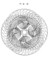
- Fig. 10 is a view of the tracks of rotations of the high-speed agitator blades relative to the low-speed agitator blade when a low-speed shaft is supposed to be stationarily fixed;
- Fig. 11 is a plan view showing a second embodiment of the present invention; and
- Fig. 12 is schematic views showing agitator blades of the second embodiment.
- The structure and operation of a batch-type viscous liquid processor according to a first embodiment of the present invention will now be described in detail with reference to Figs. 1 to 9.
- This embodiment is a batch-type viscous liquid processor including two horizontal shafts for agitating viscous liquid of high-molecular polymer or the like for the purpose of a process such as polycondensation, bulk polymerization, solution polymerization, gas-liquid reaction and monomer degradation.
- In these drawings, reference numeral 1 denotes a casing which has a bottom portion corresponding to the tracks of outer peripheral ends of agitator blades which will be explained later. At the center of this bottom portion, a rib 1a is formed along the longitudinal direction of the casing 1. A low-
speed shaft 2 and a high-speed shaft 3 extending in parallel are provided horizontally between and throughside walls 1b on both longitudinal ends of the casing 1, and theshafts shafts - A low-
speed agitator blade 4 is of a shape as shown in Fig. 4. An odd-number (e.g., five) of such blades at different phases are securely fixed on the low-speed shaft 2 so as to form a tandem pattern. Each of the low-speed agitator blades 4 is constituted of a plurality of (e.g., four) radiallysectorial blade members 5 which are made by machining the intermediate portions cut away from a thick disk at the same intervals. A jacket through which a thermal medium flows is formed on the inside of each of thesectorial blade members 5 if necessary. As illustrated in Fig. 7, the cross section of thesectorial blade member 5 is formed to be a parallelogram so that the leading end of the blade member as viewed in a direction of rotation of the low-speed agitator blade 4 defines an acute angle, and that the opposite end of the same end surface as the leading end defines an obtuse angle. The acute-angled end serves as ashearing edge 5a, and its inclined surface has a liquid delivering function to an, extent of a thickness (h) thereof. The low-speed agitator blades 4 are each securely fixed on the low-speed shaft 2 through aboss 6. - Further, one end of a
scraper rod 7 is fastened on the trailing outer peripheral end of eachsectorial blade member 5 of the low-speed agitator blade 4 as viewed in the direction of rotation, and the other end of thescraper rod 7 is fastened on the leading outer peripheral end of eachsectorial blade member 5 of theadjacent agitator blade 4. Thus,such scraper rods 7 are located in a continuous spiral pattern. - On the other hand, an even-number (e.g., eight) of high-
speed agitator blades speed shaft 3 so as to form a tandem pattern. As shown in Figs. 5 and 6, each of the high-speed agitator blades 8 is constituted of a plurality of (e.g., two) wide sectorial blade members 10 (Fig. 5), which are substantially the same as the above-mentionedsectorial blade members 5, formed by machining the intermediate portions cut away from a thick disk, and each of the high-speed agitator blades 9 is constituted a plurality of (e.g., two) small blade members 11 (Fig. 6) having a substantially rectangular shape which are formed by further machining the sectorial blade members. Theagitator blades speed shaft 3 through a boss 13a in such a manner that theblade members blade members blade member speed agitator blade sectorial blade member 5 for low-speed agitation. Side surfaces of theseblade members sectorial blade member 5 of the low-speed agitator blade 4. - Further, one end of a
scraper rod 12 is fastened on the trailing outer peripheral end of eachsmall blade member 11 of the high-speed agitator blade 9 as viewed in the direction of rotation, and the other end of thescraper rod 12 is fastened on the trailing outer peripheral end of eachsectorial blade member 10 of theadjacent agitator blade 8 as viewed in the direction of rotation, while no scraper rod is provided between asectorial blade member 10 and asmall blade member 11 which are adjacent to each other with the above-mentioned low-speed agitator blade 4 interposed therebetween. Thus,such scraper rods 12 are located in a discontinuous spiral pattern whose lead has the same direction as the lead of the spiral pattern formed by thescraper rods 7 of the low-speed shaft 2. Thesectorial blade members 5 of the low-speed agitator blades 4 are located between suchunconnected blade members blade members speed agitator blades scraper rods 12 are relatively rotatably provided between thesectorial blade members 5 of two adjacent low-speed agitator blades 4. The condition of these blade members which are rotated across each other when they are viewed from theside wall 1b is illustrated in an area A of Fig. 2. - Next, the operation of this embodiment will be explained. Highly viscous liquid to be processed is fed into the casing 1 until it substantially reaches a level of the shaft center. When a motor (not shown) is activated, rotation of the motor is transmitted through appropriate reduction gears (not shown) to the low-
speed shaft 2 and the high-speed shaft 3 so that theseshafts speed shaft 2 and the high-speed shaft 3 will not be restricted to those of this embodiment. It can be arranged that each agitator blade of the high-speed shaft 3 has two blade members or more, and that each agitator blade of the low-speed shaft 2 has an integer times as many blade members as the agitator blade of the high-speed shaft 3, with the rotational ratio being set to be an inverse number of the number of the blade members. - Then, as illustrated in the area A of Fig. 2, the
sectorial blade members 5 of the low-speed agitator blades 4 and theblade members speed agitator blades scraper rods shearing edges sectorial blade members 5 of the low-speed agitator blades 4 and thesectorial blade members 10 and thesmall blade members 11 of the high-speed agitator blades shafts blade members scraper rods - Experiments of the first embodiment were conducted as follows:
- Diameter of a disk for an agitator blade: 134 mm
Size of a casing: 236 mmW x 168 mmH x 612 mmL
Liquid quantity: 5.6 ℓ
Reaction temperature: 330°C max
Viscous liquid: A polyester resin in an intermediate state to be further polymerized and collected as a highly polymerized resin. - According to results of the test, desired effects such as agitation/stirring efficiency, self-cleaning effciency and surface replacement efficiency were obtained from the present invention.
- A second embodiment in which the present invention is applied to a continuous-type viscous liquid processor will now be described.
- Figs. 11 and 12 illustrate the second embodiment, and the same component parts as those of the first embodiment are denoted by the same reference numerals in these drawings, explanation of such component parts being omitted except for the differences.
- In this embodiment, an inlet is formed on one of the
side walls 1b of the casing 1 (left in Fig. 11), and an outlet is formed on the other (right in Fig. 11), so that highly viscous liquid supplied from the inlet is processed while it is continuously delivered in a direction indicated by arrows a′ in the drawing, and is discharged from the outlet. - The low-
speed shaft 2 is provided with low-speed agitator blades 4A each includingsectorial blade members 5A which are substantially the same as the low-speed agitator blades 4 of the first embodiment described above, and the high-speed shaft 3 is provided with high-speed agitator blades 14 in a tandem pattern each includingsectorial blade members 10A similar to thesectorial blade members 10 of the first embodiment shown in Fig. 5, with the inclined surfaces of thesectorial blade members 5A of the low-speed agitator blades 4A being inclined in the same direction as the inclined surfaces of thesectorial blade members 10A of the high-speed agitator blades 14. Further,scraper rods 15 are fastened on the outer peripheral ends of thesectorial blade members 5A of the low-speed agitator blades 4A so as to form a continuous spiral pattern in the same manner as the first embodiment. On the other hand, each of the high-speed agitator blades 14 is securely fixed on the high-speed shaft 3 at a phase deviated from a phase of the adjacent agitator blade at an angle of 90°C, and one end of ascraper rod 16 is fastened on the leading outer peripheral end of eachsectorial blade member 10A of the high-speed agitator blade 14 as viewed in a direction of rotation, while the other end of thescraper rod 16 is fastened on the leading outer peripheral end of eachsectorial blade member 10A of theadjacent agitator blade 14,such scraper rods 12 being located in a discontinuous spiral pattern. With this arrangement, the viscous liquid supplied from the inlet will be continuously agitated and stirred, traveling in the direction of the arrows a toward the outlet. - In the embodiments described heretofore, each low-speed agitator blade has four
sectorial blade members blade members - Besides, the low-
speed shaft 2 and the high-speed shaft 3 extending in parallel are rotated in such a manner that the agitator blades on both shafts will agitate the liquid between these shafts from the upper side in the above embodiments. However, the low-speed shaft 2 and the high-speed shaft 3 may be rotated the other way round to cause the agitator blades to agitate the liquid between these shafts from the lower side. - According to the present invention, since the agitator blades on both shafts are rotated to agitate the viscous liquid between the two shafts from the upper or lower side, the viscous liquid between the shafts is pressed against the casing. Each of the inclined surfaces of the sectorial blade members made of machined disks serves to deliver the liquid to an extent of the thickness thereof, and the opposite inclined surface draws the liquid due to the negative pressure generated thereon. As a result, agitation and stirring of the viscous liquid can be performed with such a simple arrangement, and stirring of the viscous liquid can be further promoted by shearing the liquid by means of the leading edges of the sectorial blade members each of which defines an acute angle.
- Moreover, each of the agitator blades is thick, so that a jacket for thermal treatment can be formed within the agitator blade.
- Furthermore, because each of the blade members has a cross section of a parallelogram, the surfaces of the blade member are smooth and flat, thereby preventing the viscous liquid from adhering to the blade surfaces, while enabling effective scraping by the scraper rods.
Claims (5)
Applications Claiming Priority (2)
| Application Number | Priority Date | Filing Date | Title |
|---|---|---|---|
| JP287150/89 | 1989-11-02 | ||
| JP1287150A JP2925599B2 (en) | 1989-11-02 | 1989-11-02 | High viscosity liquid processing equipment |
Publications (2)
| Publication Number | Publication Date |
|---|---|
| EP0426127A1 true EP0426127A1 (en) | 1991-05-08 |
| EP0426127B1 EP0426127B1 (en) | 1994-12-28 |
Family
ID=17713722
Family Applications (1)
| Application Number | Title | Priority Date | Filing Date |
|---|---|---|---|
| EP90120831A Expired - Lifetime EP0426127B1 (en) | 1989-11-02 | 1990-10-30 | Viscous liquid processor |
Country Status (7)
| Country | Link |
|---|---|
| EP (1) | EP0426127B1 (en) |
| JP (1) | JP2925599B2 (en) |
| KR (1) | KR0144482B1 (en) |
| CN (1) | CN1035237C (en) |
| AU (1) | AU640737B2 (en) |
| CA (1) | CA2029082C (en) |
| DE (1) | DE69015577T2 (en) |
Cited By (8)
| Publication number | Priority date | Publication date | Assignee | Title |
|---|---|---|---|---|
| ES2056026A1 (en) * | 1991-12-23 | 1994-09-16 | Elf Antar France | Method for producing an asphalt binder emulsion and monitoring the viscosity and breaking properties thereof. |
| US5407266A (en) * | 1991-06-07 | 1995-04-18 | List Ag | Mixing kneader with rotating shafts and kneading bars |
| EP0774508A2 (en) * | 1995-10-30 | 1997-05-21 | Anton Steinecker Maschinenfabrik GmbH | Rotating impeller for mashing tank |
| EP1101525A1 (en) * | 1999-11-10 | 2001-05-23 | Buss- SMS GmbH Verfahrenstechnik | Mixer and reactor |
| JP2014083479A (en) * | 2012-10-22 | 2014-05-12 | Shin Nichinan:Kk | Kneading apparatus |
| CN111185131A (en) * | 2020-02-25 | 2020-05-22 | 扬州瑞邦化工技术有限公司 | Continuous production device for special-shaped high-viscosity polymer melt |
| CN111225737A (en) * | 2018-09-05 | 2020-06-02 | 田中控股株式会社 | Liquid stirring device |
| CN113279076A (en) * | 2021-06-30 | 2021-08-20 | 邱群子 | Ultrahigh molecular weight polyethylene fiber pre-traction hot water solvent collecting device |
Families Citing this family (18)
| Publication number | Priority date | Publication date | Assignee | Title |
|---|---|---|---|---|
| DE4326807A1 (en) * | 1993-08-10 | 1995-02-16 | Bayer Ag | Completely self-cleaning mixer |
| JPH0871395A (en) * | 1994-08-31 | 1996-03-19 | Sumitomo Heavy Ind Ltd | Use of high viscosity liquid continuous treatment apparatus equipped with two horizontal shafts |
| JPH09136025A (en) * | 1995-11-13 | 1997-05-27 | Sumitomo Heavy Ind Ltd | High viscosity liquid treatment apparatus |
| JP3203174B2 (en) * | 1995-11-13 | 2001-08-27 | 住友重機械工業株式会社 | High viscosity liquid processing and high speed liquid processing equipment |
| KR100479511B1 (en) * | 2000-11-21 | 2005-03-30 | 정석이 | Agitation apparatus |
| JP3657541B2 (en) * | 2001-07-16 | 2005-06-08 | 月島機械株式会社 | Stirring heat transfer device |
| JP2005220242A (en) * | 2004-02-06 | 2005-08-18 | Mitsubishi Chemicals Corp | Method for producing aliphatic or alicyclic polyester |
| JP4936106B2 (en) * | 2006-03-24 | 2012-05-23 | 宇部興産機械株式会社 | Stir dryer |
| DE102008048580B4 (en) * | 2008-09-23 | 2014-08-21 | List Holding Ag | Device for carrying out mechanical, chemical and / or thermal processes |
| US8079753B2 (en) | 2008-11-18 | 2011-12-20 | 1350363 Alberta Ltd. | Agitator tool for progressive cavity pump |
| CN101837273A (en) * | 2009-03-19 | 2010-09-22 | 上海亦晨信息科技发展有限公司 | Combined type three-cavity hybrid reactor and method thereof |
| KR101066273B1 (en) * | 2009-06-12 | 2011-09-20 | 안동철 | Fluid heating device |
| JP6083733B2 (en) * | 2012-11-12 | 2017-02-22 | 日工株式会社 | Continuous mixer |
| JP6771908B2 (en) * | 2016-03-14 | 2020-10-21 | 株式会社栗本鐵工所 | Stirring blade structure for kneading stirrer |
| CN108236910B (en) * | 2018-01-31 | 2020-04-10 | 浙江大学 | Agitating unit and horizontal biax automatically cleaning reactor |
| JP6870018B2 (en) * | 2019-03-18 | 2021-05-12 | 株式会社栗本鐵工所 | Stirring blade structure for kneading stirrer |
| JP2020044536A (en) * | 2019-12-20 | 2020-03-26 | 株式会社栗本鐵工所 | Agitation blade structure for kneading agitation device |
| CN114367222A (en) * | 2022-01-18 | 2022-04-19 | 青岛大厨四宝餐料有限公司 | Be used for old hen powder seasoning processing to use horizontal blending tank |
Citations (7)
| Publication number | Priority date | Publication date | Assignee | Title |
|---|---|---|---|---|
| US3346242A (en) * | 1965-08-14 | 1967-10-10 | List Heinz | Mixing machine |
| DE2012294A1 (en) * | 1969-03-17 | 1970-10-01 | Heinz List | Mixing and kneading machine |
| FR2090808A5 (en) * | 1970-04-27 | 1972-01-14 | Mitsubishi Heavy Ind Ltd | |
| FR2344602A1 (en) * | 1976-03-18 | 1977-10-14 | Bayer Ag | PERFECTED PROCESS AND REACTOR FOR THE PRODUCTION OF COPPER PHTHALOCYANIN |
| EP0144092A2 (en) * | 1983-12-05 | 1985-06-12 | Dipl.-Ing. H. List Industrielle Verfahrenstechnik | Mixing and kneading machine |
| WO1988004198A1 (en) * | 1986-12-11 | 1988-06-16 | Heinz Nienhaus | Multi-axial mixing drier or reactor |
| EP0329092A1 (en) * | 1988-02-16 | 1989-08-23 | List AG | Mixer-kneader with plural shafts |
-
1989
- 1989-11-02 JP JP1287150A patent/JP2925599B2/en not_active Expired - Fee Related
-
1990
- 1990-10-30 DE DE69015577T patent/DE69015577T2/en not_active Expired - Fee Related
- 1990-10-30 EP EP90120831A patent/EP0426127B1/en not_active Expired - Lifetime
- 1990-10-31 CA CA002029082A patent/CA2029082C/en not_active Expired - Lifetime
- 1990-11-01 KR KR90017715A patent/KR0144482B1/en not_active IP Right Cessation
- 1990-11-01 CN CN90108888A patent/CN1035237C/en not_active Expired - Fee Related
-
1991
- 1991-02-06 AU AU70275/91A patent/AU640737B2/en not_active Ceased
Patent Citations (7)
| Publication number | Priority date | Publication date | Assignee | Title |
|---|---|---|---|---|
| US3346242A (en) * | 1965-08-14 | 1967-10-10 | List Heinz | Mixing machine |
| DE2012294A1 (en) * | 1969-03-17 | 1970-10-01 | Heinz List | Mixing and kneading machine |
| FR2090808A5 (en) * | 1970-04-27 | 1972-01-14 | Mitsubishi Heavy Ind Ltd | |
| FR2344602A1 (en) * | 1976-03-18 | 1977-10-14 | Bayer Ag | PERFECTED PROCESS AND REACTOR FOR THE PRODUCTION OF COPPER PHTHALOCYANIN |
| EP0144092A2 (en) * | 1983-12-05 | 1985-06-12 | Dipl.-Ing. H. List Industrielle Verfahrenstechnik | Mixing and kneading machine |
| WO1988004198A1 (en) * | 1986-12-11 | 1988-06-16 | Heinz Nienhaus | Multi-axial mixing drier or reactor |
| EP0329092A1 (en) * | 1988-02-16 | 1989-08-23 | List AG | Mixer-kneader with plural shafts |
Cited By (11)
| Publication number | Priority date | Publication date | Assignee | Title |
|---|---|---|---|---|
| US5407266A (en) * | 1991-06-07 | 1995-04-18 | List Ag | Mixing kneader with rotating shafts and kneading bars |
| ES2056026A1 (en) * | 1991-12-23 | 1994-09-16 | Elf Antar France | Method for producing an asphalt binder emulsion and monitoring the viscosity and breaking properties thereof. |
| EP0774508A2 (en) * | 1995-10-30 | 1997-05-21 | Anton Steinecker Maschinenfabrik GmbH | Rotating impeller for mashing tank |
| EP0774508A3 (en) * | 1995-10-30 | 2002-06-05 | Anton Steinecker Maschinenfabrik GmbH | Rotating impeller for mashing tank |
| EP1101525A1 (en) * | 1999-11-10 | 2001-05-23 | Buss- SMS GmbH Verfahrenstechnik | Mixer and reactor |
| JP2014083479A (en) * | 2012-10-22 | 2014-05-12 | Shin Nichinan:Kk | Kneading apparatus |
| CN111225737A (en) * | 2018-09-05 | 2020-06-02 | 田中控股株式会社 | Liquid stirring device |
| CN111185131A (en) * | 2020-02-25 | 2020-05-22 | 扬州瑞邦化工技术有限公司 | Continuous production device for special-shaped high-viscosity polymer melt |
| CN111185131B (en) * | 2020-02-25 | 2024-01-26 | 扬州瑞邦科技发展有限公司 | Special-shaped high-viscosity polymer melt continuous production device |
| CN113279076A (en) * | 2021-06-30 | 2021-08-20 | 邱群子 | Ultrahigh molecular weight polyethylene fiber pre-traction hot water solvent collecting device |
| CN113279076B (en) * | 2021-06-30 | 2022-03-29 | 邱群子 | Ultrahigh molecular weight polyethylene fiber pre-traction hot water solvent collecting device |
Also Published As
| Publication number | Publication date |
|---|---|
| DE69015577D1 (en) | 1995-02-09 |
| AU7027591A (en) | 1992-08-20 |
| JP2925599B2 (en) | 1999-07-28 |
| KR0144482B1 (en) | 1998-07-15 |
| CN1051682A (en) | 1991-05-29 |
| AU640737B2 (en) | 1993-09-02 |
| CA2029082C (en) | 1999-12-21 |
| DE69015577T2 (en) | 1995-05-11 |
| KR910009329A (en) | 1991-06-28 |
| CA2029082A1 (en) | 1991-05-03 |
| JPH03151033A (en) | 1991-06-27 |
| EP0426127B1 (en) | 1994-12-28 |
| CN1035237C (en) | 1997-06-25 |
Similar Documents
| Publication | Publication Date | Title |
|---|---|---|
| EP0426127B1 (en) | Viscous liquid processor | |
| CA2040009C (en) | Agitator | |
| US5230562A (en) | Viscous liquid processor | |
| EP0470493B1 (en) | Mixing apparatus | |
| US5669710A (en) | Completely self-cleaning mixer/reactor | |
| CA1290745C (en) | Kneader-mixer | |
| US3640509A (en) | Apparatus for continuous reaction of high-viscous materials | |
| JPS60208209A (en) | Same-direction rotating type double screw kneader with kneading plate | |
| EP0807210A1 (en) | A continuous dynamic mixing system and methods for operating such system | |
| CA2222711A1 (en) | Food processing vat | |
| JP2000199684A (en) | Indirect heating stirrer/dryer | |
| JPH0618618B2 (en) | Stirrer | |
| JPH0871395A (en) | Use of high viscosity liquid continuous treatment apparatus equipped with two horizontal shafts | |
| JP3197179B2 (en) | Stirrer | |
| JP4766905B2 (en) | Paddle blade and stirring device provided with the paddle blade | |
| JP4291930B2 (en) | Mixing equipment for highly viscous products | |
| JPS6271521A (en) | Method and apparatus for agitating at low speed | |
| JPH0642733Y2 (en) | Stirrer | |
| SU1053870A1 (en) | Apparatus for suspension polymerization | |
| JPH03267136A (en) | Vertical type stirrer | |
| IE44917B1 (en) | Polymerization reactor | |
| JP3197194B2 (en) | Stirrer | |
| JPH08266881A (en) | Impeller and agitator provided with the impeller | |
| KR930019366A (en) | Stirring method and stirring device for viscous material | |
| JP2000015076A (en) | Stirring apparatus |
Legal Events
| Date | Code | Title | Description |
|---|---|---|---|
| PUAI | Public reference made under article 153(3) epc to a published international application that has entered the european phase |
Free format text: ORIGINAL CODE: 0009012 |
|
| AK | Designated contracting states |
Kind code of ref document: A1 Designated state(s): AT BE CH DE DK ES FR GB GR IT LI LU NL SE |
|
| 17P | Request for examination filed |
Effective date: 19911028 |
|
| 17Q | First examination report despatched |
Effective date: 19930401 |
|
| RBV | Designated contracting states (corrected) |
Designated state(s): CH DE FR GB IT LI |
|
| GRAA | (expected) grant |
Free format text: ORIGINAL CODE: 0009210 |
|
| AK | Designated contracting states |
Kind code of ref document: B1 Designated state(s): CH DE FR GB IT LI |
|
| ITF | It: translation for a ep patent filed |
Owner name: JACOBACCI CASETTA & PERANI S.P.A. |
|
| REF | Corresponds to: |
Ref document number: 69015577 Country of ref document: DE Date of ref document: 19950209 |
|
| ET | Fr: translation filed | ||
| PLBE | No opposition filed within time limit |
Free format text: ORIGINAL CODE: 0009261 |
|
| STAA | Information on the status of an ep patent application or granted ep patent |
Free format text: STATUS: NO OPPOSITION FILED WITHIN TIME LIMIT |
|
| 26N | No opposition filed | ||
| REG | Reference to a national code |
Ref country code: GB Ref legal event code: IF02 |
|
| PGFP | Annual fee paid to national office [announced via postgrant information from national office to epo] |
Ref country code: CH Payment date: 20081031 Year of fee payment: 19 Ref country code: DE Payment date: 20081027 Year of fee payment: 19 |
|
| PGFP | Annual fee paid to national office [announced via postgrant information from national office to epo] |
Ref country code: IT Payment date: 20081028 Year of fee payment: 19 |
|
| PGFP | Annual fee paid to national office [announced via postgrant information from national office to epo] |
Ref country code: FR Payment date: 20081014 Year of fee payment: 19 |
|
| PGFP | Annual fee paid to national office [announced via postgrant information from national office to epo] |
Ref country code: GB Payment date: 20081029 Year of fee payment: 19 |
|
| REG | Reference to a national code |
Ref country code: CH Ref legal event code: PCAR Free format text: AMMANN PATENTANWAELTE AG BERN;SCHWARZTORSTRASSE 31;3001 BERN (CH) |
|
| REG | Reference to a national code |
Ref country code: CH Ref legal event code: PL |
|
| REG | Reference to a national code |
Ref country code: FR Ref legal event code: ST Effective date: 20100630 |
|
| PG25 | Lapsed in a contracting state [announced via postgrant information from national office to epo] |
Ref country code: FR Free format text: LAPSE BECAUSE OF NON-PAYMENT OF DUE FEES Effective date: 20091102 Ref country code: DE Free format text: LAPSE BECAUSE OF NON-PAYMENT OF DUE FEES Effective date: 20100501 |
|
| PG25 | Lapsed in a contracting state [announced via postgrant information from national office to epo] |
Ref country code: CH Free format text: LAPSE BECAUSE OF NON-PAYMENT OF DUE FEES Effective date: 20091031 Ref country code: LI Free format text: LAPSE BECAUSE OF NON-PAYMENT OF DUE FEES Effective date: 20091031 |
|
| PG25 | Lapsed in a contracting state [announced via postgrant information from national office to epo] |
Ref country code: GB Free format text: LAPSE BECAUSE OF NON-PAYMENT OF DUE FEES Effective date: 20091030 |
|
| PG25 | Lapsed in a contracting state [announced via postgrant information from national office to epo] |
Ref country code: IT Free format text: LAPSE BECAUSE OF NON-PAYMENT OF DUE FEES Effective date: 20091030 |