EP0426114A2 - Keyless vehicle lock system - Google Patents
Keyless vehicle lock system Download PDFInfo
- Publication number
- EP0426114A2 EP0426114A2 EP90120807A EP90120807A EP0426114A2 EP 0426114 A2 EP0426114 A2 EP 0426114A2 EP 90120807 A EP90120807 A EP 90120807A EP 90120807 A EP90120807 A EP 90120807A EP 0426114 A2 EP0426114 A2 EP 0426114A2
- Authority
- EP
- European Patent Office
- Prior art keywords
- vehicle
- switch
- lock
- door
- portable
- Prior art date
- Legal status (The legal status is an assumption and is not a legal conclusion. Google has not performed a legal analysis and makes no representation as to the accuracy of the status listed.)
- Granted
Links
Images


Classifications
-
- B—PERFORMING OPERATIONS; TRANSPORTING
- B60—VEHICLES IN GENERAL
- B60R—VEHICLES, VEHICLE FITTINGS, OR VEHICLE PARTS, NOT OTHERWISE PROVIDED FOR
- B60R25/00—Fittings or systems for preventing or indicating unauthorised use or theft of vehicles
- B60R25/20—Means to switch the anti-theft system on or off
- B60R25/2063—Ignition switch geometry
-
- G—PHYSICS
- G07—CHECKING-DEVICES
- G07C—TIME OR ATTENDANCE REGISTERS; REGISTERING OR INDICATING THE WORKING OF MACHINES; GENERATING RANDOM NUMBERS; VOTING OR LOTTERY APPARATUS; ARRANGEMENTS, SYSTEMS OR APPARATUS FOR CHECKING NOT PROVIDED FOR ELSEWHERE
- G07C9/00—Individual registration on entry or exit
- G07C9/00174—Electronically operated locks; Circuits therefor; Nonmechanical keys therefor, e.g. passive or active electrical keys or other data carriers without mechanical keys
- G07C9/00309—Electronically operated locks; Circuits therefor; Nonmechanical keys therefor, e.g. passive or active electrical keys or other data carriers without mechanical keys operated with bidirectional data transmission between data carrier and locks
- G07C2009/00555—Electronically operated locks; Circuits therefor; Nonmechanical keys therefor, e.g. passive or active electrical keys or other data carriers without mechanical keys operated with bidirectional data transmission between data carrier and locks comprising means to detect or avoid relay attacks
-
- G—PHYSICS
- G07—CHECKING-DEVICES
- G07C—TIME OR ATTENDANCE REGISTERS; REGISTERING OR INDICATING THE WORKING OF MACHINES; GENERATING RANDOM NUMBERS; VOTING OR LOTTERY APPARATUS; ARRANGEMENTS, SYSTEMS OR APPARATUS FOR CHECKING NOT PROVIDED FOR ELSEWHERE
- G07C9/00—Individual registration on entry or exit
- G07C9/00174—Electronically operated locks; Circuits therefor; Nonmechanical keys therefor, e.g. passive or active electrical keys or other data carriers without mechanical keys
- G07C2009/00753—Electronically operated locks; Circuits therefor; Nonmechanical keys therefor, e.g. passive or active electrical keys or other data carriers without mechanical keys operated by active electrical keys
- G07C2009/00769—Electronically operated locks; Circuits therefor; Nonmechanical keys therefor, e.g. passive or active electrical keys or other data carriers without mechanical keys operated by active electrical keys with data transmission performed by wireless means
- G07C2009/00793—Electronically operated locks; Circuits therefor; Nonmechanical keys therefor, e.g. passive or active electrical keys or other data carriers without mechanical keys operated by active electrical keys with data transmission performed by wireless means by Hertzian waves
-
- G—PHYSICS
- G07—CHECKING-DEVICES
- G07C—TIME OR ATTENDANCE REGISTERS; REGISTERING OR INDICATING THE WORKING OF MACHINES; GENERATING RANDOM NUMBERS; VOTING OR LOTTERY APPARATUS; ARRANGEMENTS, SYSTEMS OR APPARATUS FOR CHECKING NOT PROVIDED FOR ELSEWHERE
- G07C2209/00—Indexing scheme relating to groups G07C9/00 - G07C9/38
- G07C2209/60—Indexing scheme relating to groups G07C9/00174 - G07C9/00944
- G07C2209/63—Comprising locating means for detecting the position of the data carrier, i.e. within the vehicle or within a certain distance from the vehicle
Definitions
- the present invention relates to a vehicle keyless lock system for controlling one or more door locks and/or a vehicle control lock such as a steering lock without using any key.
- Japanese Patent Provisional (KOKAI) Publications Nos. 63-1765 and 63-4182 disclose vehicle keyless lock systems which enable the driver of a vehicle to unlock a vehicle door or a steering system merely by pushing a request switch if the driver carries a card for radiating radio waves, on the person.
- a keyless lock system for a vehicle comprises a portable communicating means, an onboard communicating means, a primary (detecting) means, a final (controlling) means, and a (main) controlling means.
- the portable communicating means (such as an entry card) transmits a cipher code signal
- the onboard communicating means (such as an antenna connected with a circuitry) receives the code signal.
- the primary means senses the position of at least one monitored door of the vehicle to determine whether the monitored door is in a closed state or in an open state.
- the final means produces a first (card) warning signal in response to a first alarm command signal of the controlling means.
- the controlling means produces an automatic request signal when the door is moved between the open state and the closed state, ascertains the existence of the portable means by receiving the code signal through the onboard communicating means when the automatic request signal is produced, and produces the alarm command signal to command the final means to produce the warning signal if the portable communicating means is absent. Therefore, this keyless lock system can prevent the loss of the portable communicating means by producing the warning signal when the door is operated.
- a keyless lock system for a vehicle comprises a portable communicating means for transmitting microwaves, an onboard communicating means for receiving microwaves from the portable communicating means, an actuating means for actuating at least one lock unit of the vehicle in response to an actuation command signal, and a controlling means for calculating a distance between the portable communicating means and the onboard communicating means by using a microwave propagation time (or propagation delay), determining, in dependence on the calculated distance, whether the portable communicating means is in a predetermined area or not, and producing the actuation command signal to actuate the lock unit only when the portable communicating means is in the predetermined area. Therefore, this keyless lock system can locate the portable communicating means accurately and speedily without being readily influenced by elecromagnetic noise waves and metallic obstructions.
- Fig. 1 shows an arrangement of various functional means used in the first embodiment.
- the arrangement shown in Fig. 1 approximately corresponds to the invention claimed in original Claim 13.
- the keyless lock control system of the first embodiment comprises a portable communicating means PCM, an onboard communicating means OCM, a primary (detecting) means PM, a final (controlling) means FM, and a controlling means CM.
- the portable communicating means PCM comprises a pocket device which is an entry card in this embodiment, and the onboard communicating means OCM comprises one or more antennas. Both communicating means are designed to perform radio communication.
- the primary means PM comprises various switches and sensors.
- the final means FM comprises a warning means WM for producing a warning signal to the driver, and an actuating means AM for actuating one or more lock units of the vehicle.
- the controlling means CM receives signals from the primary means PM and controls the final means FM by sending one or more command signals in accordance with the input signals sent from the primary means PM.
- the controlling means CM of this embodiment comprises a condition discriminating means DM for receiving the signals from the primary means PM, and produces at least one request signal, and a request examining means EM which receives the request signal, determines whether the portable means is present in a predetermined area or not, and produces the command signal in dependence on the result of the determination.
- the primary means PM comprises a door position sensing means DPSM which comprises a first door position switch DPSW1 for detecting the position of a monitored door MD of the vehicle and a second door position switch DPSW2 for detecting the position of a controlled door CD of the vehicle.
- the primary means PM further comprises first and second request switch RSW1 and RSW2, and a vehicle control main selector switch VCSW which is connected with a steering system SS, an accessory system AS and an ignition system IG of the vehicle.
- the primary means PM further comprises a door lock sensing means DLSM and a vehicle state sensing means VSSM connected with an automatic transmission AT of the vehicle.
- the warning means WM may comprises a first warning device WD1 ssfor producing a first warning signal and a second warning device WD2 for producing a second warning signal
- the actuating means AM comprises a first lock actuator LA1 for actuating a first lock unit LU1 and a second lock actuator LA2 for actuating a second lock unit LU2.
- the discriminating means DM comprises first and second door condition discriminating means DDM1 and DDM2; and first, second and third switch condition discriminating means SD1, SDM2 and SDM3.
- the examining means EM comprises an automatic request examining means AREM; and first and second switch request examining means SREM1 and SREM2.
- the pocket device of the portable communicating means PCM is an entry card 21, as shown in Fig. 2.
- the card 21 can transmit a predetermined cipher code signal.
- the onboard communicating means OCM comprises a door control antenna 23, a trunk control antenna 25 and an ignition control antenna 27 which are all mounted on the vehicle.
- the door antenna 23 is mounted on a front door of the driver seat's side near the outside handle.
- the door antenna 23 can receive the code signal when the driver stands near the driver door with the card 21. It is optional to provide another antenna on the other front door.
- the trunk antenna 25 is a built-in antenna located inside a rear bumper of the vehicle.
- the trunk antenna 25 can receive the code signal when the driver stands with the card 21 near a trunk lid of the vehicle.
- the ignition control antenna 27 is located outside a steering lock unit near the driver's seat.
- a control unit 29 is connected with each of the antennas 23, 25 and 27.
- the control unit 29 includes an antenna selector circuit 31 for selectively making connection to any one of the antennas 23, 25 and 27, a duplexer circuit 33, a receiving (receiver) circuit 35, a transmitting (transmitter) circuit 37, and a control section 39.
- the duplexer circuit 33 connects the receiving circuit 35 with the selector 31 during a receiving period, and connects the transmitting circuit 37 with the selector 31 during a transmitting period.
- the control section 39 includes a central processing unit of a microcomputer, and serves as the controlling means CM.
- the control section 39 receives the code signal from the card 21 through one of the antennas 23, 25 and 27, and sends the code signal through an input and output circuit 47 to a steering lock unit 49.
- the control section 39 is connected through a reset circuit 41 with an interface circuit 43.
- the control section 39 is further connected through an interface circuit 45 with a buzzer 46 serving as the warning means WM, and various switches of the primary means PM>
- the peripheral devices connected with the interface circuit 45 are at least one door position switch DPS, at least one door lock switch DLS, a vehicle speed sensor VSS, an automatic transmission position switch ATS, and a vehicle control main selector switch VCSW including an ignition switch IGS which is connected with a battery BTT.
- a plurality of door position switches DPS for sensing the positions of all the doors of the vehicle.
- the door position switches are connected in parallel to each other between a ground and the interface circuit 45.
- the interface circuit 43 is connected with at least one door request switch DRS and a trunk request switch TRS provided in the trunk lid of the vehicle.
- the door request switch DRS is located on the driver's front door near the outside door handle. It is optional to provide another door request switch in the other front door.
- the steering lock unit 49 has a control section 51 which includes a central processing unit of a microcomputer.
- the control section 51 receives the cipher code signal and other information from the control unit 29 through an input and output circuit 53, and performs various control operations to lock and unlock the steering system of the vehicle.
- the control section 51 is connected through a reset circuit 55 with a key request switch KRS.
- the key request switch KRS is further connected through the interface circuit 43 with the reset circuit 41.
- the reset circuit 55 resets the control section 51 to a prescribed state, and at the same time the reset circuit 41 resets the control section 39 to a prescribed state.
- the control section 51 is further connected with a memory section 57 which stores request codes for requesting various information items from the control unit 29.
- the steering lock unit 49 further includes a checking section 59 which is connected with the control section 51, and a memory section 61 for storing cipher code data.
- the checking section 59 collates the cipher code signal sent from the card 21 through the control unit 29, with the cipher code data stored in the memory section 61. If the cipher code signal of the card 21 is in complete agreement with the code data of the memory section 61, then the checking section 59 sends an agreement signal to the control section 51.
- a driver circuit 63 is connected with the control section 51 and a latch solenoid 65. The control section 51 actuates the latch solenoid 65 through the driver circuit 63 in accordance with the agreement signal of the checking section 59.
- a switch SWG is put in a closed state only when the selector switch is in an ACC position or a spare key is inserted in a key hole formed in the steering lock unit.
- the steering lock unit 49 further includes a steering locking means for locking the steering system of the vehicle, a steering unlocking means for unlocking the steering system, and an inhibiting means for preventing the unlocking operation of the steering unlocking means. (These means are not shown in the figures.)
- the driver circuit 63 and the latch solenoid 65 serve as a releasing means for cancelling the inhibition of the inhibiting means.
- the control section 51 actuates the latch solenoid 65 to cancell the inhibition of the inhibiting means.
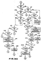
- the keyless lock control system of the first embodiment is operated as shown in Figs. 3A, 3B and 3C.
- step S1 the controlling means of the keyless lock control system determines wether the ignition switch IGS is in the on state or not. If it is not, the control system proceeds to a step S2 to determine whether the vehicle control main selector switch VCSW is in the ACC position for turing on the electric accessory system of the vehicle. If the answer of the decision step S2 is negative, then the control system proceeds to a step S3 shown in Fig. 3B through a connector point B. At the step S3, the control system determines whether the key request switch KRS is in the on state or not.
- the control system determines at a step S11 whether the door request switch DRS is in the on state or not. When the driver pushes the door request switch DRS (to a request position), the door request switch DRS is turned on, and the control system proceeds to a step S13.
- the control unit 29 carries out communication with the card 21 which is held by the driver standing near the driver's door.
- the control unit 29 transmits an interrogation signal from the door antenna 23 to the card 21 when the door request switch DRS is switched on, and the card 21 transmits the code signal automatically when the card 21 receives the correct interrogation signal.
- the control system compares the code signal of the card 21 with the stored code data to note points of disagreement, and determines whether the correct card 21 exists in a predetermined door operating area.
- the door operating area is an area near the outside handle of the driver's door. If the card 21 is absent in the predetermined door operating area, then the control system returns from the step S15 to the step S1 through a connector point X.
- step S17 determines whether the doors are in the closed state or not. If at least one door is not in the closed state, then the control system produces, at a step S19, a door warning signal to warn the driver that the doors are not closed securely. From the step S19, the control system returns to the step S1 through the connector point X. When the answer of the step S17 is affirmative, then the control system proceeds to a step S21 to determine whether the driver's door is in the locked state or not. If the door is in the locked state, then the control system proceeds to a step S23 to determine whether the control system is in a low sensitivity mode or not.
- control system proceeds to a step S25 to restore the sensitivity to a normal level, and perform a predetermined check operation; and then returns to the step S1 through the connector point X. If the control system is not in the low sensitivity mode but in a normal mode, then the control system proceeds from the step S23 to a step S27. At the step S27, the control system delivers a door unlock command signal to the door lock actuator, and by so doing unlocks the driver's door. Then, the control system returns from the step S27 to the step S1 through the connector point X. In this way, the driver having the card 21 can open the driver's door and enter the vehicle.
- the door request switch DRS corresponds to the second request switch RSW2 shown in Fig. 1; the step S11 corresponds to the second switch condition discriminating means SDM2; and the steps S13, S15, S21 and S27 correspond to the second switch request examining means SREM2.
- the door lock switch DLS serves as the door lock sensing means DLSM.
- the keyless lock control system of the first embodiment enables the driver to start the engine as follows: When the vehicle main selector switch VCSW is not turned to the accessory (ACC) position, and the ignition switch is still in the off state, the control system reaches the step S3 through the steps S1 and S2 and the connector point B. When the driver pushes the key request switch KRS, then the key request switch KRS is turned on, and remains on until released. Therefore, the control system proceeds from the step S3 to a step S4. At the step S4, the control system sends the interrogation signal to the card 21 and receives the cipher code signal from the card 21.
- the control system determines whether the card 21 exists in a predetermined key operating area, which is, for example, an area located at and near the driver's seat. If the card 21 is nonexisting in the key operating area, then the control system actuates the buzzer 46 at a step S7 to warn the driver with a buzzing sound that the card 21 is missing. After the step S7, the control system returns to the step S1. If the card 21 exists in the key operating area, then the control system proceeds from the step S5 to a step S9. At the step S9, the control unit 29 transmits the cipher code signal received from the card 21, a request code for requesting the collation of the checking section 59 and other information, to the steering lock unit 49.
- the checking section 59 checks the code signal of the card 21 to ascertain that the code signal is in complete agreement with the stored code. If the agreement is confirmed, the steering lock unit 49 releases a button 49b (shown in Fig. 4) for a limited time duration, and allows the driver to turn the vehicle control selector switch VCSW to start the engine. If the code signal sent from the card 21 is not in complete agreement with the stored code, then the steering lock unit 49 holds the lock button 49b immovable, and the vehicle control switch VCSW inoperable to protect the vehicle against theft.
- the key request switch KRS corresponds to the first request switch RSW1 shown in Fig. 1; the step S3 corresponds to the first switch condition discriminating means SDM1; and the steps S4 and S5 corresponds to the first switch request examining means SREM1.
- the control system proceeds from the step S1 to a step S53 to determine whether the electric accessory system is in the on state.
- the control system checks the state of the key request switch KRS at a step S55. If the key rewuest switch KRS is in the off state, the control system proceeds to a step S57 to check the state of the door request switch DRS.
- step S87 the control system determines whether the driver's door is in the open state or not. If the door is in the closed state, the control system proceeds directly to a step S91 to check the state of the key request switch KRS. When the key request switch KRS is in the off state, the control system proceeds to the step S57.
- the control system proceeds to a step S59 if the door request switch DRS is in the off state.
- the control system determines whether a monitored door of the vehicle is moved from the open state to the closed state. In this example, the answer of the step S59 becomes affirmative when the monitored door is in the closed state in the current execution of the step S59 although the monitored door was in the open state in the last execution of the step S59. It is convenient to use for the step S59 a flag (or condition code) indicating the open and closed states of the monitored door.
- the control system monitors the positions of all the doors of the vehicle, and makes an affirmative answer to the step S59 if any one or more of allt he doors of the vehicle is moved from the open state to the closed state.
- the control system returns to the step S1 when the answer of the step S59 is negative, and proceeds to a step S61 when the answer of the step S59 is affirmative.
- the control unit 29 performs radio communication with the card 21.
- the control system determines whether the card 21 exists in a predetermined safe area. For example, the control system determines whether the card 21 exists in the passenger compartment of the vehicle. If the card 21 is absent in the safe area, the control system proceeds from the step S63 to a step S65.
- the control system actuates the buzzer 46 to producea card warning signal indicating the absence of the card 21.
- the control system returns to the step S1.
- the step S59 corresponds to the first door condition discriminating means DDM1, and the steps S61 and S63 correspond to the automatic request examining means AREM.
- D The control system prevents the driver from leaving the vehicle without locking the steering system.
- step S87 determines whether the driver door is in the open state or not. If the door is open, the control system proceeds to a step S89. At the step S89, the control system actuates the buzzer 46 to produce a steering lock warning signal to warn that the steering lock is forgotton.
- the step S87 may be so designed that the answer of the step S87 is affirmative when either or both of the left and right front doors in in the open state. It is optional to employ a warning device which is used only for the steering lock warning of the step S89.
- step S91 determines whether the key request switch KRS is in the on state or not. If the key request switch KRS is in the off state, the control system proceeds to the step S57, at which the control system determines whether the door request switch DRS is in the on state or not. If the door request switch DRS is in the on state, then the control system proceeds to a step S67 shown in Fig. 3C, through a connector point C. At the step S67, the control system determines whether any one or more of the vehicle doors is in the open state. If all the doors are in the closed state, then the control system proceeds from the step S67 to a step 75.
- the control system determines whether the driver's door is in the locked state or not. If the driver's door is not in the locked state, then the control system returns from the step S75 to the step S1 through the connector point X. Therefore, the control system of this embodiment prevents the keyless lock operation when the steering system is not locked, and by so doing makes the driver aware of the steering lock.
- the control system proceeds from the step S67 to a step S69 to perform radio communication with the card 21.
- the control system determines whether the card 21 exists in the predetermined door operating area. If the card 21 exists in the door operating area, then the control system produces a door warning signal at a step S73 to warn that at least one door is not securely closed.
- step S77 the control system determines whether the radio receiving mode is in the low sensitivity mode or not. If it is, the control system restores the sensitivity to the normal level at a step S78, and then proceeds to a step S79. If the answer of the step S77 is negative, then the control system proceeds directly to the step S79.
- the control unit 29 performs radio communication with the card 21 at the step S79, and determines, at a step S81, whether the card 21 exists in the door operating area. If the card 21 is detected in the door operating area, then the control system unlocks the driver's door by producing a door unlock command signal at a step S83.
- the step S87 corresponds to the second door condition discriminating means DDM2, and the step S57 corresponds to the third switch condition discriminating means SDM3.
- the driver can stop the engine by turning the vehicle control main selector switch VCSW from the ON position to the ACC position.
- the control system proceeds to the step S87 through the step S2. If the driver's door remains in the closed state, then the control system proceeds to the step S91 to determine whether the key request switch KRS is in the on state. When the key request switch KRS is in the on state, then the control system proceeds from the step S91 to a step S93 to determine whether at least one of the door request switch DRS and the trunk request switch TRS is in the on state. If both of the request switches DRS and TRS are in the off state, the control system proceeds from the step S93 to a step S95 to perform radio communication with the card 21.
- the control system determines, at a step S97, whether the card 21 exists in the predetermined key operating area which is, for example, an interior area at and near the driver's seat. If the card 21 exists in the key operating area, then the control system determines, at a step S101, the current value of the vehicle speed V of the vehicle sensed by the vehicle speed sensor VSS, and determines, at a step S103 whether the vehicle is in motion or at rest. If the vehicle is moving, then the control system returns to the step S1 through the connector point X. In this way, the control system improves the safety of the vehicle by making it impossible to lock the steering system while the vehicle is moving.
- the control system proceeds from the step S103 to a step S105 to determine whether the automatic transmission is in the parking range. In this example, it is determined whether the driver's shift lever is in the parking position or not. If the automatic transmission is not in the parking range, then the control system returns to the step S1. In this way, the control system can improve the safety of the vehicle by inhibiting the steering lock while the shift lever is out of the parking position.
- the control sstem proceeds from the step S105 to a step S107.
- the control unit 29 transmits the cipher code signal of the card 21, the request code for requesting the collation of the checking section 59 and other information, to the steering lock unit 49. Therefore, the steering lock unit 49 releases the bottom 49b and allows the driver to turn the selector switch VCSW from the ACC position to the LOCK position to lock the steering system if the cipher code signal of the card 21 is in complete agreement with the stored code.
- control system proceeds from the step S97 to a step S99 to actuate the buzzer 46 to warn that the card 21 is missing.
- the step S91 corresponds to a first lock request signal producing means of the first switch condition discriminating means SDM1, and the steps S95, S97, S101, S103 and S105 correspond to a first lock command signal producing means of the first switch request examining means SREM1.
- the step S3 corresponds to a first unlock request signal producing means of the first switch condition discrminating means SDM1, and the steps S4 and S5 correspond to a first unlock command signal producing means of the first switch request examining means SREM1.
- the control system When the vehicle control main selector switch VCSW is turned to the LOCK position, the control system reaches the step S11 through the steps S1, S2 and S3. When the door request switch DRS is in the on state, the control system proceeds to the step S13. Therefore, the control system performs radio communication with the card 21 at the step S13, determines, at the step S15, whether the card 21 exists in the predetermined door operationg area, and determines, at the step S17, whether all the doors are in the closed state. If all the doors are securely closed, then the control system determines, at the step S21, whether the driver's door is in the locked state or not. If the driver door is not locked, then the control system locks all the doors by producing a door lock command signal at a step S29.
- the control system detects the position of the card 21 at a step S31, and determines, at a step S33, whether the card 21 is left behind in the passenger compartment. If the card 21 is not in the passenger compartment, then the control system returns from the step S33 to the Step S1. If the card 21 is forgotton in the passenger compartment, the control system proceeds to a step S35, and changes the radio receiving mode to the low sensitivity mode by lowering the sensitivity to a low level. Therefore, if an unauthorized person pushes the door request switch DRS, the control sytem prevents the door from being unlocked by preventing radio communication between the control unit 29 and the card 21 left behind in the passenger compartment.
- the control system reaches a step S37 through the steps S3 and S11.
- the control system determines, at the step S37, whether the trunk request switch TRS is in the on state or not, and proceeds to a step S39 if the trunk request switch TRS is in the off state.
- the control system determines at least one door is in the unlocked state. If all the doors are in the locked state, the control system determines, at a step S41, whether at least one door is changed from the unlocked state to the locked state.
- step S41 If at least one door is in the locked state in the current execution of the step S41 although hat door was in the unlocked state in the previous execution, then the control system proceeds from the step S41 to the Step S31. If the answer of the step S41 is negative, then the control system returns from the step S41 to the step S1. If at least one door is in the unlocked state, then the control system proceeds from the step S39 to a step S43 to restore the sensitivity of the control unit 29. From the step S43, the control system returns to the step S1.
- the control system proceeds from the step S37 to a step S45, at which the control unit 29 performs radio communication with the card 21. Then, the control system determines, at a step S47, whether the card 21 exists in a predetermined trunk operating area near the trunk lid of the vehicle. If the card 21 is missing, then the control system directly returns to the step S1. If the card 21 is present in the trunk operating area, then the control system opens the trunk lid by producing a trunk open command signal at a step S49. From the step S49, the control system returns to the step S1.
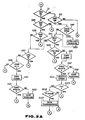
- Fig. 4 illustrates operations of the steering lock unit 49.
- the steering lock unit 49 has a selector member 49a and a bottom 49b.
- the selector member 49a is rotatable from the LOCK position, through the ACC position and the ON position, to the ST (Start) position. Between the LOCK position and the ON position, there is only the ACC position, and there is no OFF position.
- the selector member 49a is movable between the LOCK position and the ACC position only while the bottom 49b is pushed.
- the selector member 49a is a movable component of the vehicle control main selector switch VCSW, and simultaneously a component of the ignition switch IGWS.
- the selector member 49a is a component of the key request switch KRS.
- the key request switch KRS is switched on when the selector member 49a is pushed.
- the ignition switch IGS is operated by turning the selector member 49a.
- the radio communication is performed when the driver pushes the selector member 49a to turn on the key request switch KRS. If the driver carries the card 21, the control system releases the button 49b. Therefore, the driver can turn the selector member 49a from the LOCK position to the ACC position by pushing the buttonm 49b, as shown in a step S207.
- the steering lock unit 49 is resistant to being tampered by a child, as shown in a step S203, because it is necessary to push the selector member 49a and the button 49a in order to turn the selector 49a. If the driver does not have the card 21, the control system holds the button 49b immovable, and provudes the card warning signal, as shown in a step S205. Therefore, the driver cannot push the button 49b, and cannot turn the selector member 49a.
- the selector member 49a is freely movable between the ACC position and the ST position. Therefore, the driver can start the engine of the vehicle by turning the selector member 49a from the ACC position to the ST position, as shown in a step S209. The select member 49a automatically returns to the ON position, as shown in a step S211, after the engine starting operation.
- the control system ascertains the existence of the card 21 in the predetermined safe area each time any of the doors is brought from the open state to the closed state. If the driver does not have the card 21 in the vehicle, then the control system produces the card warning signal to warn that the card 21 is missing, as shown in a step S215.
- the driver can stop the engine by turning the selector member 49a from the ON position to the ACC position, as shown in a step S217.
- the selector member 49a is freely movable between the ST position and the ACC position. If the driver's door is opened while the selector member 49a is in the ACC position, then the control system produces the steering lock warning signal to warn the steering lock is forgotton, as shown in a step S219.
- the driver In order to turn the selector member 49a from the ACC position to the LOCK position to lock the steering system, the driver must push the selector member 49a in the ACC position and further push the button 49b, as shown in steps S221 and S229. If the card 21 is missing in the key operating area, the button 49b remains incapable of being pushed, so that the selector member 49a is incapable of being turned to the LOCK position, and the card warning signal is produced, as shown in a step S223. When the shift lever of the automatic transmission is out of the parking position, or the vehicle speed is greater than zero, then the button 49b is not released, as shown in a step S225 and S227.
- the driver can turn the selector member 49a to the LOCK position only when the card 21 exists in the predetermined area, and the vehicle is at rest.
- the vehicle is equipped with a manual transmission, it is necessary to omit the step S225 from Fig. 4, and the step S105 from Fig. 3A, and to employ only the vehicle speed check shown in the step S103 and S227.
- the automatic transmission it is optional to employ only one of the vehicle sp[eed check of the step S103 and the parking range check of the step S105.
- the vehicle control main selector switch VCSW of this example has only the LOCK position for locking the steering system, the ACC position for turning on the electric accessories such as an air conditioning system and a sound system, the ON position for the normal vehicle operation, and the ST position for starting the engine. Unlike the conventional ignition switch, the vehicle control main selector switch VCSW of this example has no OFF position. Therefore, when the vehicle control selector switch VCSW is out of the LOCK position, the accessories are always operative, so that the driver can readily notice the selector switch VCS being out of the LOCK position.
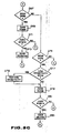
- a second embodiment of the present invention is shown in Figs. 5-8c.
- a keyless lock control system of the second embodiment is designed to calculate a distance between a keyless entry card 21 and an antenna by using a propagation time of radio waves.
- the keyless lock control system of the second embodiment is almost the same as the keyless lock control system of the first embodiment, but different in the following points.
- the keyless lock control system of the second embodiment has only two antennas, a center antenna 24 and a trunk control antenna 25.
- the trunk antenna 25 is provided in the rear bumper, as in the first embodiment.
- the center antenna 24 is disposed at a central portion 13 of the vehicle shown in Fig. 6.
- the keyless lock control system of the second embodiment employs a microwave system utilizing microwaves, and the card 21 is capable of transmitting microwaves.
- the control section 39 of the control unit 29 is designed to measure a propagation time (or propagation delay) of microwaves received by the center antenna 24, to calculate a distance between the card 21 and the center antenna 24 by using the propagation time, and to determine the position of the card 21.
- the control section 39 serves as a measuring means for measuring the propagation time, and as a calculating means for calculating the distance between the card 21 and the center antenna 24.
- the control section 39 comprises a comparing means for comparing the calculated distance between the card 21 and the center antenana 24, with a predetermined first value.
- the control section 39 judges the card 21 to be present in a predetermined inside area AB shown in Fig. 6 if the calculated distance is equal to or smaller than the predetermined first value.
- the control section 39 judges the card 21 to be present in a predetermined outside area AA shown in Fig. 6. It is possible to further provide a second comparing means for comparing the calculated distance with a predetermined second value which is greater than the first value. In this case, the control section 39 jedges the card 21 to exist in the outside area when the calculated distance is greater than the first value, and smaller than the second value. The control section 39 sends a signal indicative of the judgement to the steering lock unit 49.
- Fig. 7 illustrates operations of the keyless lock control system of the second embodiment.
- the control system of the second embodiment allows a keyless unlock operation of a controlled door only when the controlled door is in the locked state, and the card 21 is present in the outside area AA. If the door is in the unlocked state, then the door lock control is inoperative irrespective of the position of the card 21.
- the control system allows a keyless steering unlock operation only when the card 21 is present in the inside area AB.
- the control system allows a keyless door unlock operation only when the door is in the locked state and the card 21 is present in the outside area AA. Therefore, an unauthorized person cannot enter the vehicle even if the card 21 is left in the passenger compartment.
- the control system allows the keyless door lock operation only when the door is unlocked and the card 21 is present in the outside area AA.
- the control sstem allows the keyless steering unlock operation only when the card 21 is present in the inside area AB.
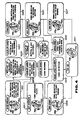
- the control procedure of the second embodiment shown in Figs. 8A, 8B and 8C is almost the same as the control procedure of the first embodiment shown in Figs. 3A, 3B and 3C.
- the steps S61, S63, S69, S71, S81, S95, S97, S4, S5, S13 and S15 are modified, and the steps S23, S25, S31, S33, S35, S39, S41 and S43 are omitted.
- the control system of the second embodiment performs microwave communication, and calculates the distance between the card 21 and the center antenna 24 by using the propagation time of the microwave signal transmitted from the card 21.
- the control system of the second embodiment determines whether the card 21 exists in the inside area AB, or not. If the card 21 is present in the inside area AB, then the control system returns to the step S1 through the connector point X. If the card 21 is absent in the inside area AB, then the control system proceeds to the step S65 to produce the card warning signal.
- the control system of the second embodiment peerforms microwave communication with the card 21 and calculates the distance between the card 21 and the center antenna 24, as in the step S61.
- the control system determines, by using the distance obtained at the step S69, whether the card 21 exists in the outside area AA, or not. Then, the control system proceeds from the step S71 to the step S73 to produce the door warning signal only when the card 21 is present in the outside area AA.
- the control system determines, by using the distance obtained at the step S79, whether the card 21 exists in the outside area AA, or not. Then, the control system proceeds from the step S81 to the step S83 to unlock the door only when the card 21 is present in the outside area AA.
- the control system determines, by using the distance obtained at the step S4, whether the card 21 exists in the inside area AB, or not. Then, the control system produces the card warning signal at the step S7 if the card 21 is not present in the inside area AB, and proceeds to the step S9 if the card 21 is present in the inside area AB.
- the control system determines, by using the distance obtained at the step S13, whether the card 21 exists in the outside area AA. Then, the control system returns to the step S1 if the card 21 is not present in the outside area AA, and proceeds to the step S17 if the card 21 exists in the outside area AA.
- the control system determines, by using the distance obtained at the step S95, whether the card 21 exists in the inside area AB, or not. Then, the control system produces the card warning signal at the step S99 if the card 21 is not present in the inside area, and proceeds to the step S101 if the card 21 is present in the inside area AB.
- the keyless lock system of the second embodiment employs only the center antenna 24 instead of the door control antenna 23 and the ignition control antenna 27. Therefore, the system of the second embodiment is advantageous in cost reduction. However, it is optional to provide two center antennas at appropriate positions in the vehicle in order to further improve the accuracy in detecting the position of the card 21.
- the keyless lock control system of the second embodiment can detect the position of the card 21 in a speedy and accurate manner, as compared with the conventional system which is arranged to detect the position of the card by monitoring the variation of the signal level of the signal received from the card.
- the conventional system is susceptible to noises of electromagnetic waves, and also in detecting the position of the card.
Abstract
Description
- The present invention relates to a vehicle keyless lock system for controlling one or more door locks and/or a vehicle control lock such as a steering lock without using any key.
- Japanese Patent Provisional (KOKAI) Publications Nos. 63-1765 and 63-4182 disclose vehicle keyless lock systems which enable the driver of a vehicle to unlock a vehicle door or a steering system merely by pushing a request switch if the driver carries a card for radiating radio waves, on the person.
- It is an object of the present invention to provide a keyless vehicle lock system which can avoid troubles due to keyless operations, and improve the vehicle's safety.
- It is an object of the present invention to provide a keyless vehicle lock system which can avoid troubles due to keyless operations, and improve the vehicle's safety.
- It is another object of the present invention to provide a keyless vehicle lock system which is speedy, accurate and resistant to noise in determining the position of an entry card for radiating radio waves.
- According to the present invention, a keyless lock system for a vehicle comprises a portable communicating means, an onboard communicating means, a primary (detecting) means, a final (controlling) means, and a (main) controlling means.
- The portable communicating means (such as an entry card) transmits a cipher code signal, and the onboard communicating means (such as an antenna connected with a circuitry) receives the code signal. The primary means senses the position of at least one monitored door of the vehicle to determine whether the monitored door is in a closed state or in an open state. The final means produces a first (card) warning signal in response to a first alarm command signal of the controlling means. The controlling means produces an automatic request signal when the door is moved between the open state and the closed state, ascertains the existence of the portable means by receiving the code signal through the onboard communicating means when the automatic request signal is produced, and produces the alarm command signal to command the final means to produce the warning signal if the portable communicating means is absent. Therefore, this keyless lock system can prevent the loss of the portable communicating means by producing the warning signal when the door is operated.
- According to another aspect of the present invention, a keyless lock system for a vehicle comprises a portable communicating means for transmitting microwaves, an onboard communicating means for receiving microwaves from the portable communicating means, an actuating means for actuating at least one lock unit of the vehicle in response to an actuation command signal, and a controlling means for calculating a distance between the portable communicating means and the onboard communicating means by using a microwave propagation time (or propagation delay), determining, in dependence on the calculated distance, whether the portable communicating means is in a predetermined area or not, and producing the actuation command signal to actuate the lock unit only when the portable communicating means is in the predetermined area. Therefore, this keyless lock system can locate the portable communicating means accurately and speedily without being readily influenced by elecromagnetic noise waves and metallic obstructions.
-
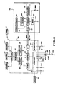
- Fig. 1 is a block diagram for schematically showing a keyless lock control system according to a first embodiment of the invention.
- Fig. 2 is a block diagram showing a control unit of the first embodiment.
- Figs. 3A, 3B and 3C are flowcharts showing a control procedure performed by the keyless lock control system of the first embodiment.
- Fig. 4 is a view for illustrating operations of a steering lock unit of the first embodiment.
- Fig. 5 is a block diagram showing a keyless lock system according to a second embodiment of the present invention.
- Fig. 6 is a view showing an inside area and an outside area of a vehicle, between which the keyless lock system of the second embodiment is arranged to discriminate.
- Fig. 7 is a table for illustrating door lock control operations and steering lock control operations performed by the keyless lock system of the second embodiment.
- Figs. 8A, 8B and 8C are flowcharts showing a control procedure performed by the keyless lock control system of the second embodiment.
- Fig. 1 shows an arrangement of various functional means used in the first embodiment. The arrangement shown in Fig. 1 approximately corresponds to the invention claimed in
original Claim 13. - As shown in Fig. 1, the keyless lock control system of the first embodiment comprises a portable communicating means PCM, an onboard communicating means OCM, a primary (detecting) means PM, a final (controlling) means FM, and a controlling means CM. The portable communicating means PCM comprises a pocket device which is an entry card in this embodiment, and the onboard communicating means OCM comprises one or more antennas. Both communicating means are designed to perform radio communication. The primary means PM comprises various switches and sensors. The final means FM comprises a warning means WM for producing a warning signal to the driver, and an actuating means AM for actuating one or more lock units of the vehicle. The controlling means CM receives signals from the primary means PM and controls the final means FM by sending one or more command signals in accordance with the input signals sent from the primary means PM. The controlling means CM of this embodiment comprises a condition discriminating means DM for receiving the signals from the primary means PM, and produces at least one request signal, and a request examining means EM which receives the request signal, determines whether the portable means is present in a predetermined area or not, and produces the command signal in dependence on the result of the determination.
- In this embodiment, the primary means PM comprises a door position sensing means DPSM which comprises a first door position switch DPSW1 for detecting the position of a monitored door MD of the vehicle and a second door position switch DPSW2 for detecting the position of a controlled door CD of the vehicle. The primary means PM further comprises first and second request switch RSW1 and RSW2, and a vehicle control main selector switch VCSW which is connected with a steering system SS, an accessory system AS and an ignition system IG of the vehicle. The primary means PM further comprises a door lock sensing means DLSM and a vehicle state sensing means VSSM connected with an automatic transmission AT of the vehicle.
- In the final means FM of this embodiment, the warning means WM may comprises a first warning device WD1 ssfor producing a first warning signal and a second warning device WD2 for producing a second warning signal, and the actuating means AM comprises a first lock actuator LA1 for actuating a first lock unit LU1 and a second lock actuator LA2 for actuating a second lock unit LU2.
- In the controlling means CM, the discriminating means DM comprises first and second door condition discriminating means DDM1 and DDM2; and first, second and third switch condition discriminating means SD1, SDM2 and SDM3. The examining means EM comprises an automatic request examining means AREM; and first and second switch request examining means SREM1 and SREM2.
- In this embodiment, the pocket device of the portable communicating means PCM is an
entry card 21, as shown in Fig. 2. Thecard 21 can transmit a predetermined cipher code signal. - As shown in Fig. 2, the onboard communicating means OCM comprises a
door control antenna 23, atrunk control antenna 25 and anignition control antenna 27 which are all mounted on the vehicle. Thedoor antenna 23 is mounted on a front door of the driver seat's side near the outside handle. Thedoor antenna 23 can receive the code signal when the driver stands near the driver door with thecard 21. It is optional to provide another antenna on the other front door. Thetrunk antenna 25 is a built-in antenna located inside a rear bumper of the vehicle. Thetrunk antenna 25 can receive the code signal when the driver stands with thecard 21 near a trunk lid of the vehicle. Theignition control antenna 27 is located outside a steering lock unit near the driver's seat. - A
control unit 29 is connected with each of theantennas control unit 29 includes anantenna selector circuit 31 for selectively making connection to any one of theantennas duplexer circuit 33, a receiving (receiver)circuit 35, a transmitting (transmitter)circuit 37, and acontrol section 39. Theduplexer circuit 33 connects thereceiving circuit 35 with theselector 31 during a receiving period, and connects thetransmitting circuit 37 with theselector 31 during a transmitting period. Thecontrol section 39 includes a central processing unit of a microcomputer, and serves as the controlling means CM. Thecontrol section 39 receives the code signal from thecard 21 through one of theantennas output circuit 47 to asteering lock unit 49. Thecontrol section 39 is connected through areset circuit 41 with aninterface circuit 43. Thecontrol section 39 is further connected through aninterface circuit 45 with abuzzer 46 serving as the warning means WM, and various switches of the primary means PM> - The peripheral devices connected with the
interface circuit 45 are at least one door position switch DPS, at least one door lock switch DLS, a vehicle speed sensor VSS, an automatic transmission position switch ATS, and a vehicle control main selector switch VCSW including an ignition switch IGS which is connected with a battery BTT. In this embodiment, there are provided a plurality of door position switches DPS for sensing the positions of all the doors of the vehicle. The door position switches are connected in parallel to each other between a ground and theinterface circuit 45. On the other hand, theinterface circuit 43 is connected with at least one door request switch DRS and a trunk request switch TRS provided in the trunk lid of the vehicle. In this embodment, the door request switch DRS is located on the driver's front door near the outside door handle. It is optional to provide another door request switch in the other front door. - The
steering lock unit 49 has acontrol section 51 which includes a central processing unit of a microcomputer. Thecontrol section 51 receives the cipher code signal and other information from thecontrol unit 29 through an input andoutput circuit 53, and performs various control operations to lock and unlock the steering system of the vehicle. Thecontrol section 51 is connected through areset circuit 55 with a key request switch KRS. The key request switch KRS is further connected through theinterface circuit 43 with thereset circuit 41. When the key request switch KRS is switched on, then thereset circuit 55 resets thecontrol section 51 to a prescribed state, and at the same time thereset circuit 41 resets thecontrol section 39 to a prescribed state. Thecontrol section 51 is further connected with amemory section 57 which stores request codes for requesting various information items from thecontrol unit 29. - The
steering lock unit 49 further includes achecking section 59 which is connected with thecontrol section 51, and amemory section 61 for storing cipher code data. The checkingsection 59 collates the cipher code signal sent from thecard 21 through thecontrol unit 29, with the cipher code data stored in thememory section 61. If the cipher code signal of thecard 21 is in complete agreement with the code data of thememory section 61, then thechecking section 59 sends an agreement signal to thecontrol section 51. Adriver circuit 63 is connected with thecontrol section 51 and alatch solenoid 65. Thecontrol section 51 actuates thelatch solenoid 65 through thedriver circuit 63 in accordance with the agreement signal of thechecking section 59. A switch SWG is put in a closed state only when the selector switch is in an ACC position or a spare key is inserted in a key hole formed in the steering lock unit. - The
steering lock unit 49 further includes a steering locking means for locking the steering system of the vehicle, a steering unlocking means for unlocking the steering system, and an inhibiting means for preventing the unlocking operation of the steering unlocking means. (These means are not shown in the figures.) Thedriver circuit 63 and thelatch solenoid 65 serve as a releasing means for cancelling the inhibition of the inhibiting means. When the agreement signal is produced by the checkingsection 59, thecontrol section 51 actuates thelatch solenoid 65 to cancell the inhibition of the inhibiting means. - The keyless lock control system of the first embodiment is operated as shown in Figs. 3A, 3B and 3C.
- (A) The driver can enter the vehicle as follows:
At a step S1 shown in Fig. 3A (the controlling means of) the keyless lock control system determines wether the ignition switch IGS is in the on state or not. If it is not, the control system proceeds to a step S2 to determine whether the vehicle control main selector switch VCSW is in the ACC position for turing on the electric accessory system of the vehicle. If the answer of the decision step S2 is negative, then the control system proceeds to a step S3 shown in Fig. 3B through a connector point B. At the step S3, the control system determines whether the key request switch KRS is in the on state or not. if the key request switch KRS is in the off state, then the control system determines at a step S11 whether the door request switch DRS is in the on state or not. When the driver pushes the door request switch DRS (to a request position), the door request switch DRS is turned on, and the control system proceeds to a step S13. - At the step S13, the
control unit 29 carries out communication with thecard 21 which is held by the driver standing near the driver's door. Thecontrol unit 29 transmits an interrogation signal from thedoor antenna 23 to thecard 21 when the door request switch DRS is switched on, and thecard 21 transmits the code signal automatically when thecard 21 receives the correct interrogation signal. At a step S15, the control system compares the code signal of thecard 21 with the stored code data to note points of disagreement, and determines whether thecorrect card 21 exists in a predetermined door operating area. For example, the door operating area is an area near the outside handle of the driver's door. If thecard 21 is absent in the predetermined door operating area, then the control system returns from the step S15 to the step S1 through a connector point X. If thecorrect card 21 is detected in the door operating area, then the control system proceeds to a step S17 to determine whether the doors are in the closed state or not. If at least one door is not in the closed state, then the control system produces, at a step S19, a door warning signal to warn the driver that the doors are not closed securely. From the step S19, the control system returns to the step S1 through the connector point X. When the answer of the step S17 is affirmative, then the control system proceeds to a step S21 to determine whether the driver's door is in the locked state or not. If the door is in the locked state, then the control system proceeds to a step S23 to determine whether the control system is in a low sensitivity mode or not. If it is, the control system proceeds to a step S25 to restore the sensitivity to a normal level, and perform a predetermined check operation; and then returns to the step S1 through the connector point X. If the control system is not in the low sensitivity mode but in a normal mode, then the control system proceeds from the step S23 to a step S27. At the step S27, the control system delivers a door unlock command signal to the door lock actuator, and by so doing unlocks the driver's door. Then, the control system returns from the step S27 to the step S1 through the connector point X. In this way, the driver having thecard 21 can open the driver's door and enter the vehicle. - The door request switch DRS corresponds to the second request switch RSW2 shown in Fig. 1; the step S11 corresponds to the second switch condition discriminating means SDM2; and the steps S13, S15, S21 and S27 correspond to the second switch request examining means SREM2. The door lock switch DLS serves as the door lock sensing means DLSM.
- (B) The keyless lock control system of the first embodiment enables the driver to start the engine as follows:
When the vehicle main selector switch VCSW is not turned to the accessory (ACC) position, and the ignition switch is still in the off state, the control system reaches the step S3 through the steps S1 and S2 and the connector point B. When the driver pushes the key request switch KRS, then the key request switch KRS is turned on, and remains on until released. Therefore, the control system proceeds from the step S3 to a step S4. At the step S4, the control system sends the interrogation signal to thecard 21 and receives the cipher code signal from thecard 21. At a step S5, the control system determines whether thecard 21 exists in a predetermined key operating area, which is, for example, an area located at and near the driver's seat. If thecard 21 is nonexisting in the key operating area, then the control system actuates thebuzzer 46 at a step S7 to warn the driver with a buzzing sound that thecard 21 is missing. After the step S7, the control system returns to the step S1. If thecard 21 exists in the key operating area, then the control system proceeds from the step S5 to a step S9. At the step S9, thecontrol unit 29 transmits the cipher code signal received from thecard 21, a request code for requesting the collation of thechecking section 59 and other information, to thesteering lock unit 49. In thesteering lock unit 49, therefore, the checkingsection 59 checks the code signal of thecard 21 to ascertain that the code signal is in complete agreement with the stored code. If the agreement is confirmed, thesteering lock unit 49 releases abutton 49b (shown in Fig. 4) for a limited time duration, and allows the driver to turn the vehicle control selector switch VCSW to start the engine. If the code signal sent from thecard 21 is not in complete agreement with the stored code, then thesteering lock unit 49 holds thelock button 49b immovable, and the vehicle control switch VCSW inoperable to protect the vehicle against theft. - The key request switch KRS corresponds to the first request switch RSW1 shown in Fig. 1; the step S3 corresponds to the first switch condition discriminating means SDM1; and the steps S4 and S5 corresponds to the first switch request examining means SREM1.
- (C) When the vehicle control main switch VCSW is in the ACC position or the ON position (the vehicle unlock state):
- When the ignition switch IGS is in the on state for switching on the ignition system, the control system proceeds from the step S1 to a step S53 to determine whether the electric accessory system is in the on state. When the answer of the step S53 is affirmative, the control system checks the state of the key request switch KRS at a step S55. If the key rewuest switch KRS is in the off state, the control system proceeds to a step S57 to check the state of the door request switch DRS.
- When the vehicle control main selector switch VCSW is in the ACC position for turning off the ignition switch IGS and turning on the accessory system, the control system reaches a step S87 through the steps S1 and S2. At the step S87, the control system determines whether the driver's door is in the open state or not. If the door is in the closed state, the control system proceeds directly to a step S91 to check the state of the key request switch KRS. When the key request switch KRS is in the off state, the control system proceeds to the step S57.
- From the step S57, the control system proceeds to a step S59 if the door request switch DRS is in the off state. At the step S59, the control system determines whether a monitored door of the vehicle is moved from the open state to the closed state. In this example, the answer of the step S59 becomes affirmative when the monitored door is in the closed state in the current execution of the step S59 although the monitored door was in the open state in the last execution of the step S59. It is convenient to use for the step S59 a flag (or condition code) indicating the open and closed states of the monitored door. In this example, the control system monitors the positions of all the doors of the vehicle, and makes an affirmative answer to the step S59 if any one or more of allt he doors of the vehicle is moved from the open state to the closed state. The control system returns to the step S1 when the answer of the step S59 is negative, and proceeds to a step S61 when the answer of the step S59 is affirmative. At the step S61, the
control unit 29 performs radio communication with thecard 21. At a next step S63, the control system determines whether thecard 21 exists in a predetermined safe area. For example, the control system determines whether thecard 21 exists in the passenger compartment of the vehicle. If thecard 21 is absent in the safe area, the control system proceeds from the step S63 to a step S65. At the step S65, the control system actuates thebuzzer 46 to producea card warning signal indicating the absence of thecard 21. After the step S65, the control system returns to the step S1. - The step S59 corresponds to the first door condition discriminating means DDM1, and the steps S61 and S63 correspond to the automatic request examining means AREM. (D) The control system prevents the driver from leaving the vehicle without locking the steering system.
- If the driver opens the driver's door while the veicle control main selector switch VCSW is in the ACC position, the control system proceeds from the step S2 to a step S87 to determine whether the driver door is in the open state or not. If the door is open, the control system proceeds to a step S89. At the step S89, the control system actuates the
buzzer 46 to produce a steering lock warning signal to warn that the steering lock is forgotton. The step S87 may be so designed that the answer of the step S87 is affirmative when either or both of the left and right front doors in in the open state. It is optional to employ a warning device which is used only for the steering lock warning of the step S89. From the step S89 or the step S87, the control system proceeds to a step S91 to determine whether the key request switch KRS is in the on state or not. If the key request switch KRS is in the off state, the control system proceeds to the step S57, at which the control system determines whether the door request switch DRS is in the on state or not. If the door request switch DRS is in the on state, then the control system proceeds to a step S67 shown in Fig. 3C, through a connector point C. At the step S67, the control system determines whether any one or more of the vehicle doors is in the open state. If all the doors are in the closed state, then the control system proceeds from the step S67 to astep 75. At the step S75, the control system determines whether the driver's door is in the locked state or not. If the driver's door is not in the locked state, then the control system returns from the step S75 to the step S1 through the connector point X. Therefore, the control system of this embodiment prevents the keyless lock operation when the steering system is not locked, and by so doing makes the driver aware of the steering lock. - If any one or more of the doors is in the open state, the control system proceeds from the step S67 to a step S69 to perform radio communication with the
card 21. At a step S71 following the step S69, the control system determines whether thecard 21 exists in the predetermined door operating area. If thecard 21 exists in the door operating area, then the control system produces a door warning signal at a step S73 to warn that at least one door is not securely closed. - If the driver's door is locked, and accordingly the answer of the step S75 is affirmative, then the control system proceeds from the step S75 to a step S77. At the step S77, the control system determines whether the radio receiving mode is in the low sensitivity mode or not. If it is, the control system restores the sensitivity to the normal level at a step S78, and then proceeds to a step S79. If the answer of the step S77 is negative, then the control system proceeds directly to the step S79. The
control unit 29 performs radio communication with thecard 21 at the step S79, and determines, at a step S81, whether thecard 21 exists in the door operating area. If thecard 21 is detected in the door operating area, then the control system unlocks the driver's door by producing a door unlock command signal at a step S83. - The step S87 corresponds to the second door condition discriminating means DDM2, and the step S57 corresponds to the third switch condition discriminating means SDM3.
- (E) The driver can stop the engine as follows:
- The driver can stop the engine by turning the vehicle control main selector switch VCSW from the ON position to the ACC position. In this case, the control system proceeds to the step S87 through the step S2. If the driver's door remains in the closed state, then the control system proceeds to the step S91 to determine whether the key request switch KRS is in the on state. When the key request switch KRS is in the on state, then the control system proceeds from the step S91 to a step S93 to determine whether at least one of the door request switch DRS and the trunk request switch TRS is in the on state. If both of the request switches DRS and TRS are in the off state, the control system proceeds from the step S93 to a step S95 to perform radio communication with the
card 21. Then, the control system determines, at a step S97, whether thecard 21 exists in the predetermined key operating area which is, for example, an interior area at and near the driver's seat. If thecard 21 exists in the key operating area, then the control system determines, at a step S101, the current value of the vehicle speed V of the vehicle sensed by the vehicle speed sensor VSS, and determines, at a step S103 whether the vehicle is in motion or at rest. If the vehicle is moving, then the control system returns to the step S1 through the connector point X. In this way, the control system improves the safety of the vehicle by making it impossible to lock the steering system while the vehicle is moving. - When the vehicle is not moving, the control system proceeds from the step S103 to a step S105 to determine whether the automatic transmission is in the parking range. In this example, it is determined whether the driver's shift lever is in the parking position or not. If the automatic transmission is not in the parking range, then the control system returns to the step S1. In this way, the control system can improve the safety of the vehicle by inhibiting the steering lock while the shift lever is out of the parking position.
- If the automatic transmission is in the parking range, the control sstem proceeds from the step S105 to a step S107. At the step S107, the
control unit 29 transmits the cipher code signal of thecard 21, the request code for requesting the collation of thechecking section 59 and other information, to thesteering lock unit 49. Therefore, thesteering lock unit 49 releases the bottom 49b and allows the driver to turn the selector switch VCSW from the ACC position to the LOCK position to lock the steering system if the cipher code signal of thecard 21 is in complete agreement with the stored code. - If the card is not detected in the key operating area, then the control system proceeds from the step S97 to a step S99 to actuate the
buzzer 46 to warn that thecard 21 is missing. - The step S91 corresponds to a first lock request signal producing means of the first switch condition discriminating means SDM1, and the steps S95, S97, S101, S103 and S105 correspond to a first lock command signal producing means of the first switch request examining means SREM1. On the other hand, the step S3 corresponds to a first unlock request signal producing means of the first switch condition discrminating means SDM1, and the steps S4 and S5 correspond to a first unlock command signal producing means of the first switch request examining means SREM1.
- (F) The driver can get off the vehicle as follows:
- When the vehicle control main selector switch VCSW is turned to the LOCK position, the control system reaches the step S11 through the steps S1, S2 and S3. When the door request switch DRS is in the on state, the control system proceeds to the step S13. Therefore, the control system performs radio communication with the
card 21 at the step S13, determines, at the step S15, whether thecard 21 exists in the predetermined door operationg area, and determines, at the step S17, whether all the doors are in the closed state. If all the doors are securely closed, then the control system determines, at the step S21, whether the driver's door is in the locked state or not. If the driver door is not locked, then the control system locks all the doors by producing a door lock command signal at a step S29. - Then, the control system detects the position of the
card 21 at a step S31, and determines, at a step S33, whether thecard 21 is left behind in the passenger compartment. If thecard 21 is not in the passenger compartment, then the control system returns from the step S33 to the Step S1. If thecard 21 is forgotton in the passenger compartment, the control system proceeds to a step S35, and changes the radio receiving mode to the low sensitivity mode by lowering the sensitivity to a low level. Therefore, if an unauthorized person pushes the door request switch DRS, the control sytem prevents the door from being unlocked by preventing radio communication between thecontrol unit 29 and thecard 21 left behind in the passenger compartment. - (G) The driver can open the trunk lid as follows:
- When the key request switch KRS and the door request switch DRS are both in the off state, then the control system reaches a step S37 through the steps S3 and S11. The control system determines, at the step S37, whether the trunk request switch TRS is in the on state or not, and proceeds to a step S39 if the trunk request switch TRS is in the off state. At the step S39, the control system determines at least one door is in the unlocked state. If all the doors are in the locked state, the control system determines, at a step S41, whether at least one door is changed from the unlocked state to the locked state. If at least one door is in the locked state in the current execution of the step S41 although hat door was in the unlocked state in the previous execution, then the control system proceeds from the step S41 to the Step S31. If the answer of the step S41 is negative, then the control system returns from the step S41 to the step S1. If at least one door is in the unlocked state, then the control system proceeds from the step S39 to a step S43 to restore the sensitivity of the
control unit 29. From the step S43, the control system returns to the step S1. - When the trunk request switch TRS is in the on state, the control system proceeds from the step S37 to a step S45, at which the
control unit 29 performs radio communication with thecard 21. Then, the control system determines, at a step S47, whether thecard 21 exists in a predetermined trunk operating area near the trunk lid of the vehicle. If thecard 21 is missing, then the control system directly returns to the step S1. If thecard 21 is present in the trunk operating area, then the control system opens the trunk lid by producing a trunk open command signal at a step S49. From the step S49, the control system returns to the step S1. - Fig. 4 illustrates operations of the
steering lock unit 49. Thesteering lock unit 49 has aselector member 49a and a bottom 49b. Theselector member 49a is rotatable from the LOCK position, through the ACC position and the ON position, to the ST (Start) position. Between the LOCK position and the ON position, there is only the ACC position, and there is no OFF position. Theselector member 49a is movable between the LOCK position and the ACC position only while the bottom 49b is pushed. Theselector member 49a is a movable component of the vehicle control main selector switch VCSW, and simultaneously a component of the ignition switch IGWS. Furthermore, theselector member 49a is a component of the key request switch KRS. The key request switch KRS is switched on when theselector member 49a is pushed. The ignition switch IGS is operated by turning theselector member 49a. - At a step S201, the radio communication is performed when the driver pushes the
selector member 49a to turn on the key request switch KRS. If the driver carries thecard 21, the control system releases thebutton 49b. Therefore, the driver can turn theselector member 49a from the LOCK position to the ACC position by pushing thebuttonm 49b, as shown in a step S207. Thesteering lock unit 49 is resistant to being tampered by a child, as shown in a step S203, because it is necessary to push theselector member 49a and thebutton 49a in order to turn theselector 49a. If the driver does not have thecard 21, the control system holds thebutton 49b immovable, and provudes the card warning signal, as shown in a step S205. Therefore, the driver cannot push thebutton 49b, and cannot turn theselector member 49a. - The
selector member 49a is freely movable between the ACC position and the ST position. Therefore, the driver can start the engine of the vehicle by turning theselector member 49a from the ACC position to the ST position, as shown in a step S209. Theselect member 49a automatically returns to the ON position, as shown in a step S211, after the engine starting operation. - At a step S213, the control system ascertains the existence of the
card 21 in the predetermined safe area each time any of the doors is brought from the open state to the closed state. If the driver does not have thecard 21 in the vehicle, then the control system produces the card warning signal to warn that thecard 21 is missing, as shown in a step S215. - The driver can stop the engine by turning the
selector member 49a from the ON position to the ACC position, as shown in a step S217. Theselector member 49a is freely movable between the ST position and the ACC position. If the driver's door is opened while theselector member 49a is in the ACC position, then the control system produces the steering lock warning signal to warn the steering lock is forgotton, as shown in a step S219. - In order to turn the
selector member 49a from the ACC position to the LOCK position to lock the steering system, the driver must push theselector member 49a in the ACC position and further push thebutton 49b, as shown in steps S221 and S229. If thecard 21 is missing in the key operating area, thebutton 49b remains incapable of being pushed, so that theselector member 49a is incapable of being turned to the LOCK position, and the card warning signal is produced, as shown in a step S223. When the shift lever of the automatic transmission is out of the parking position, or the vehicle speed is greater than zero, then thebutton 49b is not released, as shown in a step S225 and S227. Therefore, the driver can turn theselector member 49a to the LOCK position only when thecard 21 exists in the predetermined area, and the vehicle is at rest. When the vehicle is equipped with a manual transmission, it is necessary to omit the step S225 from Fig. 4, and the step S105 from Fig. 3A, and to employ only the vehicle speed check shown in the step S103 and S227. In the case of the automatic transmission, it is optional to employ only one of the vehicle sp[eed check of the step S103 and the parking range check of the step S105. - The vehicle control main selector switch VCSW of this example has only the LOCK position for locking the steering system, the ACC position for turning on the electric accessories such as an air conditioning system and a sound system, the ON position for the normal vehicle operation, and the ST position for starting the engine. Unlike the conventional ignition switch, the vehicle control main selector switch VCSW of this example has no OFF position. Therefore, when the vehicle control selector switch VCSW is out of the LOCK position, the accessories are always operative, so that the driver can readily notice the selector switch VCS being out of the LOCK position.
- A second embodiment of the present invention is shown in Figs. 5-8c. A keyless lock control system of the second embodiment is designed to calculate a distance between a
keyless entry card 21 and an antenna by using a propagation time of radio waves. - As shown in Fig. 5, the keyless lock control system of the second embodiment is almost the same as the keyless lock control system of the first embodiment, but different in the following points.
- The keyless lock control system of the second embodiment has only two antennas, a
center antenna 24 and atrunk control antenna 25. Thetrunk antenna 25 is provided in the rear bumper, as in the first embodiment. Thecenter antenna 24 is disposed at acentral portion 13 of the vehicle shown in Fig. 6. The keyless lock control system of the second embodiment employs a microwave system utilizing microwaves, and thecard 21 is capable of transmitting microwaves. - The
control section 39 of thecontrol unit 29 is designed to measure a propagation time (or propagation delay) of microwaves received by thecenter antenna 24, to calculate a distance between thecard 21 and thecenter antenna 24 by using the propagation time, and to determine the position of thecard 21. Thecontrol section 39 serves as a measuring means for measuring the propagation time, and as a calculating means for calculating the distance between thecard 21 and thecenter antenna 24. Thecontrol section 39 comprises a comparing means for comparing the calculated distance between thecard 21 and the center antenana 24, with a predetermined first value. Thecontrol section 39 judges thecard 21 to be present in a predetermined inside area AB shown in Fig. 6 if the calculated distance is equal to or smaller than the predetermined first value. If the calculated distance is greater than the predetermined first value, thecontrol section 39 judges thecard 21 to be present in a predetermined outside area AA shown in Fig. 6. It is possible to further provide a second comparing means for comparing the calculated distance with a predetermined second value which is greater than the first value. In this case, thecontrol section 39 jedges thecard 21 to exist in the outside area when the calculated distance is greater than the first value, and smaller than the second value. Thecontrol section 39 sends a signal indicative of the judgement to thesteering lock unit 49. - Fig. 7 illustrates operations of the keyless lock control system of the second embodiment.
- When the vehicle control main selector switch VCSW is in the ACC position: In this case, the control system of the second embodiment allows a keyless unlock operation of a controlled door only when the controlled door is in the locked state, and the
card 21 is present in the outside area AA. If the door is in the unlocked state, then the door lock control is inoperative irrespective of the position of thecard 21. The control system allows a keyless steering unlock operation only when thecard 21 is present in the inside area AB. - When the vehicle control main selector switch VCSW is in the LOCK position (or in the OFF position), that is when the ignition system and the accessory system are both in the off state: In this case, the control system allows a keyless door unlock operation only when the door is in the locked state and the
card 21 is present in the outside area AA. Therefore, an unauthorized person cannot enter the vehicle even if thecard 21 is left in the passenger compartment. The control system allows the keyless door lock operation only when the door is unlocked and thecard 21 is present in the outside area AA. Furthermore, the control sstem allows the keyless steering unlock operation only when thecard 21 is present in the inside area AB. - The control procedure of the second embodiment shown in Figs. 8A, 8B and 8C is almost the same as the control procedure of the first embodiment shown in Figs. 3A, 3B and 3C. In the second embodiment, the steps S61, S63, S69, S71, S81, S95, S97, S4, S5, S13 and S15 are modified, and the steps S23, S25, S31, S33, S35, S39, S41 and S43 are omitted.
- At the step S61, the control system of the second embodiment performs microwave communication, and calculates the distance between the
card 21 and thecenter antenna 24 by using the propagation time of the microwave signal transmitted from thecard 21. At the step S63, the control system of the second embodiment determines whether thecard 21 exists in the inside area AB, or not. If thecard 21 is present in the inside area AB, then the control system returns to the step S1 through the connector point X. If thecard 21 is absent in the inside area AB, then the control system proceeds to the step S65 to produce the card warning signal. - At each of the steps S69, S79, S95, S4 and S13, the control system of the second embodiment peerforms microwave communication with the
card 21 and calculates the distance between thecard 21 and thecenter antenna 24, as in the step S61. - At the step S71 shown in Fig. 8C, the control system determines, by using the distance obtained at the step S69, whether the
card 21 exists in the outside area AA, or not. Then, the control system proceeds from the step S71 to the step S73 to produce the door warning signal only when thecard 21 is present in the outside area AA. - At the step S81, the control system determines, by using the distance obtained at the step S79, whether the
card 21 exists in the outside area AA, or not. Then, the control system proceeds from the step S81 to the step S83 to unlock the door only when thecard 21 is present in the outside area AA. - At the step S5 shown in Fig. 8B, the control system determines, by using the distance obtained at the step S4, whether the
card 21 exists in the inside area AB, or not. Then, the control system produces the card warning signal at the step S7 if thecard 21 is not present in the inside area AB, and proceeds to the step S9 if thecard 21 is present in the inside area AB. - At the step S15, the control system determines, by using the distance obtained at the step S13, whether the
card 21 exists in the outside area AA. Then, the control system returns to the step S1 if thecard 21 is not present in the outside area AA, and proceeds to the step S17 if thecard 21 exists in the outside area AA. - At the step S97 shown in Fig. 8A, the control system determines, by using the distance obtained at the step S95, whether the
card 21 exists in the inside area AB, or not. Then, the control system produces the card warning signal at the step S99 if thecard 21 is not present in the inside area, and proceeds to the step S101 if thecard 21 is present in the inside area AB. - The keyless lock system of the second embodiment employs only the
center antenna 24 instead of thedoor control antenna 23 and theignition control antenna 27. Therefore, the system of the second embodiment is advantageous in cost reduction. However, it is optional to provide two center antennas at appropriate positions in the vehicle in oder to further improve the accuracy in detecting the position of thecard 21. - The keyless lock control system of the second embodiment can detect the position of the
card 21 in a speedy and accurate manner, as compared with the conventional system which is arranged to detect the position of the card by monitoring the variation of the signal level of the signal received from the card. The conventional system is susceptible to noises of electromagnetic waves, and also in detecting the position of the card.
Claims (19)
a portable communicating means for transmitting a code signal;
an onboard communicating means for receiving said code signal from said portable means;
a primary means for sensing a position of a monitored door of the vehicle to determine whether the door is in a closes state or in an open state;
a final means for producing a first warning signal in responseto a first alarm command signal; and
a controlling means for producing an automatic request signal when the door is moved between the open state and the closed state, ascertaining an existence of said portable means by receiving said code signal through said onboard means when said automatic request signal is produced, and producing said alarm command signal if said portable means is absent.
a portable communicating means for transmitting microwaves;
an onboard communicating means for receiving microwaves from said portable communicating means;
an actuating means for actuating a lock unit of the vehicle in response to an actuation command signal; and
a controlling means for calculating a distance between said portable communicating means and said onboard communicating means by using a microwave propagation time, determining, in dependence on said distance, whether said portable communicating means is in a predetermined area or not, and producing said actuation command signal only when said portable communicating means is in said predetermined area.
Applications Claiming Priority (4)
| Application Number | Priority Date | Filing Date | Title |
|---|---|---|---|
| JP1284947A JPH03148352A (en) | 1989-11-02 | 1989-11-02 | Keyless controller for vehicle |
| JP28494689A JP2507815B2 (en) | 1989-11-02 | 1989-11-02 | Vehicleless controller |
| JP284946/89 | 1989-11-02 | ||
| JP284947/89 | 1989-11-02 |
Publications (3)
| Publication Number | Publication Date |
|---|---|
| EP0426114A2 true EP0426114A2 (en) | 1991-05-08 |
| EP0426114A3 EP0426114A3 (en) | 1991-09-18 |
| EP0426114B1 EP0426114B1 (en) | 1997-02-26 |
Family
ID=26555679
Family Applications (1)
| Application Number | Title | Priority Date | Filing Date |
|---|---|---|---|
| EP90120807A Expired - Lifetime EP0426114B1 (en) | 1989-11-02 | 1990-10-30 | Keyless vehicle lock system |
Country Status (3)
| Country | Link |
|---|---|
| US (1) | US5157389A (en) |
| EP (1) | EP0426114B1 (en) |
| DE (1) | DE69029990T2 (en) |
Cited By (14)
| Publication number | Priority date | Publication date | Assignee | Title |
|---|---|---|---|---|
| EP0523602A1 (en) * | 1991-07-17 | 1993-01-20 | Bayerische Motoren Werke Aktiengesellschaft | Method for detecting portable transmitter left inside vehicle |
| EP0635408A1 (en) * | 1993-07-22 | 1995-01-25 | GEMINI ELETTRONICA s.r.l. | A safety system for vehicles |
| US5499022A (en) * | 1992-11-06 | 1996-03-12 | Valeo Electronique | Remote control system for locking and unlocking doors and other openings in a passenger space, in particular in a motor vehicle |
| EP0742127A2 (en) * | 1995-04-11 | 1996-11-13 | Tokai Rika Co., Ltd. | Vehicular starting control apparatus |
| FR2781446A1 (en) * | 1998-07-24 | 2000-01-28 | Siemens Ag | ANTI-THEFT SYSTEM FOR A MOTOR VEHICLE |
| EP0982202A2 (en) * | 1998-08-28 | 2000-03-01 | DaimlerChrysler AG | Immobilizer for a vehicle |
| EP1055789A1 (en) * | 1999-05-24 | 2000-11-29 | Valeo Securité Habitacle | Control device for locking a vehicle |
| WO2001025061A1 (en) | 1999-10-07 | 2001-04-12 | Robert Bosch Gmbh | Drive authorisation system with a circuit configuration |
| FR2807238A1 (en) * | 2000-02-22 | 2001-10-05 | Trw Inc | Remote control, for motor vehicle starter function, has multiple antennae which emit control signals received by transponder which allows operation of starting function |
| EP1143090A2 (en) * | 2000-04-03 | 2001-10-10 | Nissan Motor Company, Limited | Vehicular electronic key system |
| EP0984123A3 (en) * | 1998-08-28 | 2001-11-14 | DaimlerChrysler AG | Vehicle security system with a keyless access module |
| EP0982453A3 (en) * | 1998-08-28 | 2001-11-14 | DaimlerChrysler AG | Vehicle lock system |
| FR2843240A1 (en) * | 2002-08-05 | 2004-02-06 | Siemens Vdo Automotive | Car hands free antenna control process having parasitic signal sent second antenna group during first antenna coded signal dead time. |
| EP1410961A1 (en) * | 2002-10-17 | 2004-04-21 | Hella KG Hueck & Co. | Process for the verification of the presence of a ID-transponder within a vehicle |
Families Citing this family (30)
| Publication number | Priority date | Publication date | Assignee | Title |
|---|---|---|---|---|
| JP2901394B2 (en) * | 1991-08-09 | 1999-06-07 | アルプス電気株式会社 | Remote control device |
| AUPM402394A0 (en) * | 1994-02-23 | 1994-03-17 | Monaad Corporation Pty Limited | Security access arrangement |
| US6285296B1 (en) * | 1994-11-10 | 2001-09-04 | Audiovox Corporation | Differential range remote control |
| DE69532643T2 (en) * | 1994-11-30 | 2004-08-05 | Kabushiki Kaisha Tokai Rika Denki Seisakusho | START-UP CONTROL DEVICE FOR VEHICLES |
| US5751073A (en) * | 1996-11-20 | 1998-05-12 | General Motors Corporation | Vehicle passive keyless entry and passive engine starting system |
| KR100572815B1 (en) * | 1997-01-21 | 2006-11-30 | 코닌클리케 필립스 일렉트로닉스 엔.브이. | A product comprising an access control system for controlling access to at least one space and an access control system. |
| JPH10315914A (en) * | 1997-05-19 | 1998-12-02 | Tokai Rika Co Ltd | Starter for vehicle |
| DE19861116C2 (en) * | 1998-07-17 | 2002-05-02 | Siemens Ag | Access control device for a motor vehicle and method for adjusting the sensitivity of the access control device |
| DE19860350C5 (en) * | 1998-12-24 | 2011-01-13 | Leopold Kostal Gmbh & Co. Kg | Keyless engine start authorization control device |
| FR2794603B1 (en) * | 1999-06-01 | 2001-09-07 | Valeo Securite Habitacle | METHOD FOR BIDIRECTIONAL TRANSMISSION OF DATA, AND SYSTEM FOR IMPLEMENTING SAME |
| DE19938898C1 (en) * | 1999-08-17 | 2001-04-05 | Siemens Ag | Device for authorization identification and triggering / releasing an action, in particular electronic locking device for motor vehicles, and base unit and key unit for realizing such a device |
| WO2001025063A1 (en) * | 1999-10-04 | 2001-04-12 | Siemens Automotive Corporation | Electronic key system including ignition and transmission control |
| US6518720B1 (en) * | 2000-10-19 | 2003-02-11 | General Motors Corporation | Combination door unlock and trunk release mechanism |
| DE10114876A1 (en) * | 2001-03-26 | 2002-10-17 | Siemens Ag | Identification system for proving authorization to access or use an object, in particular a motor vehicle |
| JP3913652B2 (en) * | 2002-09-26 | 2007-05-09 | 本田技研工業株式会社 | Electronic key system for vehicles |
| JP4121345B2 (en) * | 2002-09-27 | 2008-07-23 | 本田技研工業株式会社 | Electronic key system for vehicles |
| TWI232826B (en) * | 2002-09-30 | 2005-05-21 | Honda Motor Co Ltd | Electronic key system for vehicle |
| JP4320554B2 (en) * | 2003-03-03 | 2009-08-26 | オムロン株式会社 | Remote control system for vehicles |
| JP2006321454A (en) * | 2005-05-20 | 2006-11-30 | Yamaha Motor Co Ltd | Vehicle control device for saddle riding type vehicle |
| CA2621844C (en) * | 2005-09-08 | 2014-04-22 | Cardlab Aps | A dynamic transaction card and a method of writing information to the same |
| JP2008050892A (en) * | 2006-08-28 | 2008-03-06 | Alps Electric Co Ltd | Keyless entry device |
| US20100052848A1 (en) * | 2008-08-26 | 2010-03-04 | Nissan Technical Center North America, Inc. | Remote vehicle operating system |
| US20100102924A1 (en) * | 2008-10-27 | 2010-04-29 | Lear Corporation | Remote control system and a method of control |
| US9129454B2 (en) | 2009-06-05 | 2015-09-08 | Lear Corporation | Passive entry system and method for a vehicle |
| US8284020B2 (en) * | 2009-12-22 | 2012-10-09 | Lear Corporation | Passive entry system and method for a vehicle |
| DE102012003015A1 (en) * | 2012-02-15 | 2013-08-22 | Audi Ag | Starting system for a motor vehicle, motor vehicle with a starting system and method for operating a starting system for a motor vehicle |
| MA41187A (en) | 2014-12-19 | 2021-04-07 | Cardlab Aps | PROCESS AND ASSEMBLY FOR GENERATING A MAGNETIC FIELD AND PROCESS FOR MANUFACTURING AN ASSEMBLY |
| EP3035230A1 (en) | 2014-12-19 | 2016-06-22 | Cardlab ApS | A method and an assembly for generating a magnetic field |
| EP3082071A1 (en) | 2015-04-17 | 2016-10-19 | Cardlab ApS | Device for and method of outputting a magnetic field |
| JP2021188924A (en) * | 2020-05-26 | 2021-12-13 | 株式会社東海理化電機製作所 | Control device and program |
Citations (2)
| Publication number | Priority date | Publication date | Assignee | Title |
|---|---|---|---|---|
| FR2589930A1 (en) * | 1986-04-10 | 1987-05-15 | Kokusan Kinzoku Kogyo Kk | CAR LOCKING SYSTEM CONTROLLED BY RADIO SIGNAL |
| US4763121A (en) * | 1985-08-12 | 1988-08-09 | Nissan Motor Company, Limited | Keyless entry system for automatically operating automotive door locking devices without manual operation |
Family Cites Families (12)
| Publication number | Priority date | Publication date | Assignee | Title |
|---|---|---|---|---|
| US3725939A (en) * | 1971-06-07 | 1973-04-03 | Sure Lock Syst Inc | Vehicle security system |
| US4205325A (en) * | 1977-12-27 | 1980-05-27 | Ford Motor Company | Keyless entry system |
| US4353064A (en) * | 1981-01-14 | 1982-10-05 | Honeywell Inc. | Battery operated access control card |
| JPS57163956U (en) * | 1981-04-08 | 1982-10-15 | ||
| JPS58120970A (en) * | 1982-01-14 | 1983-07-19 | 日産自動車株式会社 | Push button type electronic lock apparatus for vehicle |
| US4719460A (en) * | 1983-09-19 | 1988-01-12 | Nissan Motor Company, Limited | Keyless entry system for automotive vehicle devices with theft-prevention feature |
| US4672375A (en) * | 1983-11-29 | 1987-06-09 | Nissan Motor Company, Limited | Keyless entry system for automotive devices with compact, portable wireless code transmitter, and feature for preventing users from locking transmitter in vehicle |
| JPS60183246A (en) * | 1984-03-01 | 1985-09-18 | Nissan Motor Co Ltd | Unlocking control unit for vehicle |
| US4674073A (en) * | 1985-02-28 | 1987-06-16 | Aisin Seiki Kabushiki Kaisha | Reflective object detecting apparatus |
| JPS631765A (en) * | 1986-06-20 | 1988-01-06 | Nissan Motor Co Ltd | Ignition device |
| JPS634182A (en) * | 1986-06-24 | 1988-01-09 | 日産自動車株式会社 | Unlocking control apparatus |
| DE3805439A1 (en) * | 1988-02-22 | 1989-09-07 | Dotronic Mikroprozessortechnik | Method for using ultrasound to monitor unauthorised entry into a room (space) |
-
1990
- 1990-10-30 EP EP90120807A patent/EP0426114B1/en not_active Expired - Lifetime
- 1990-10-30 DE DE69029990T patent/DE69029990T2/en not_active Expired - Lifetime
- 1990-10-31 US US07/606,277 patent/US5157389A/en not_active Expired - Lifetime
Patent Citations (2)
| Publication number | Priority date | Publication date | Assignee | Title |
|---|---|---|---|---|
| US4763121A (en) * | 1985-08-12 | 1988-08-09 | Nissan Motor Company, Limited | Keyless entry system for automatically operating automotive door locking devices without manual operation |
| FR2589930A1 (en) * | 1986-04-10 | 1987-05-15 | Kokusan Kinzoku Kogyo Kk | CAR LOCKING SYSTEM CONTROLLED BY RADIO SIGNAL |
Cited By (21)
| Publication number | Priority date | Publication date | Assignee | Title |
|---|---|---|---|---|
| EP0523602A1 (en) * | 1991-07-17 | 1993-01-20 | Bayerische Motoren Werke Aktiengesellschaft | Method for detecting portable transmitter left inside vehicle |
| US5499022A (en) * | 1992-11-06 | 1996-03-12 | Valeo Electronique | Remote control system for locking and unlocking doors and other openings in a passenger space, in particular in a motor vehicle |
| EP0635408A1 (en) * | 1993-07-22 | 1995-01-25 | GEMINI ELETTRONICA s.r.l. | A safety system for vehicles |
| EP0742127A2 (en) * | 1995-04-11 | 1996-11-13 | Tokai Rika Co., Ltd. | Vehicular starting control apparatus |
| EP0742127A3 (en) * | 1995-04-11 | 1998-04-08 | Tokai Rika Co., Ltd. | Vehicular starting control apparatus |
| FR2781446A1 (en) * | 1998-07-24 | 2000-01-28 | Siemens Ag | ANTI-THEFT SYSTEM FOR A MOTOR VEHICLE |
| EP0982202A3 (en) * | 1998-08-28 | 2003-01-15 | DaimlerChrysler AG | Immobilizer for a vehicle |
| US6624741B1 (en) | 1998-08-28 | 2003-09-23 | Daimlerchrysler Ag | Vehicle locking system |
| EP0982202A2 (en) * | 1998-08-28 | 2000-03-01 | DaimlerChrysler AG | Immobilizer for a vehicle |
| EP0982453A3 (en) * | 1998-08-28 | 2001-11-14 | DaimlerChrysler AG | Vehicle lock system |
| EP0984123A3 (en) * | 1998-08-28 | 2001-11-14 | DaimlerChrysler AG | Vehicle security system with a keyless access module |
| EP1055789A1 (en) * | 1999-05-24 | 2000-11-29 | Valeo Securité Habitacle | Control device for locking a vehicle |
| FR2794086A1 (en) * | 1999-05-27 | 2000-12-01 | Valeo Securite Habitacle | VEHICLE LOCK CONTROL DEVICE |
| WO2001025061A1 (en) | 1999-10-07 | 2001-04-12 | Robert Bosch Gmbh | Drive authorisation system with a circuit configuration |
| FR2807238A1 (en) * | 2000-02-22 | 2001-10-05 | Trw Inc | Remote control, for motor vehicle starter function, has multiple antennae which emit control signals received by transponder which allows operation of starting function |
| EP1143090A2 (en) * | 2000-04-03 | 2001-10-10 | Nissan Motor Company, Limited | Vehicular electronic key system |
| EP1143090A3 (en) * | 2000-04-03 | 2001-10-17 | Nissan Motor Company, Limited | Vehicular electronic key system |
| US6798337B2 (en) | 2000-04-03 | 2004-09-28 | Nissan Motor Co., Ltd. | Vehicular electronic key system |
| FR2843240A1 (en) * | 2002-08-05 | 2004-02-06 | Siemens Vdo Automotive | Car hands free antenna control process having parasitic signal sent second antenna group during first antenna coded signal dead time. |
| US7119660B2 (en) | 2002-08-05 | 2006-10-10 | Siemens Vdo Automotive | Process for controlling the antennas of a hands-free system of an automotive vehicle and corresponding device |
| EP1410961A1 (en) * | 2002-10-17 | 2004-04-21 | Hella KG Hueck & Co. | Process for the verification of the presence of a ID-transponder within a vehicle |
Also Published As
| Publication number | Publication date |
|---|---|
| DE69029990T2 (en) | 1997-06-12 |
| EP0426114B1 (en) | 1997-02-26 |
| DE69029990D1 (en) | 1997-04-03 |
| US5157389A (en) | 1992-10-20 |
| EP0426114A3 (en) | 1991-09-18 |
Similar Documents
| Publication | Publication Date | Title |
|---|---|---|
| US5157389A (en) | Keyless vehicle lock system | |
| US5293160A (en) | Keyless vehicle lock system with distance measuring | |
| EP0965710B1 (en) | Vehicle control system | |
| EP1184236B9 (en) | Radio system | |
| US5499022A (en) | Remote control system for locking and unlocking doors and other openings in a passenger space, in particular in a motor vehicle | |
| EP0735219B1 (en) | Hands-free remote entry system | |
| EP1659543B1 (en) | Security system and portable device usable therein | |
| US5521443A (en) | Battery residual capacity display and operating device for an electric vehicle | |
| US7181189B2 (en) | Vehicular remote control system and tire pressure monitoring system | |
| US7425886B2 (en) | Smart entry system for vehicle | |
| US7148790B2 (en) | System for controlling a valet mode of a vehicle | |
| US8511121B2 (en) | Key holding device for in-vehicle auxiliary key | |
| EP1079053A2 (en) | Vehicle automatic door-locking system using identifier signal transmitting portable unit | |
| KR20060106727A (en) | Vehicle door control system and method | |
| EP2199503B1 (en) | Vehicle door locking system, keyless entry system, and locking control method | |
| JP3377267B2 (en) | Automotive engine starter | |
| JP4867706B2 (en) | Smart keyless device for vehicle | |
| JP2006510828A (en) | Vehicle security system | |
| EP1820704A1 (en) | Keyless entry system adapted for motor vehicle | |
| US6538559B1 (en) | Remote control apparatus and remote control method | |
| JPH07189538A (en) | Keyless entry device | |
| JP2003262058A (en) | Keyless entry device | |
| JPH0932377A (en) | Locking-release device and locking-release system | |
| JPH03148352A (en) | Keyless controller for vehicle | |
| JP3990038B2 (en) | Vehicle antitheft device |
Legal Events
| Date | Code | Title | Description |
|---|---|---|---|
| PUAI | Public reference made under article 153(3) epc to a published international application that has entered the european phase |
Free format text: ORIGINAL CODE: 0009012 |
|
| 17P | Request for examination filed |
Effective date: 19901030 |
|
| AK | Designated contracting states |
Kind code of ref document: A2 Designated state(s): DE FR GB |
|
| PUAL | Search report despatched |
Free format text: ORIGINAL CODE: 0009013 |
|
| AK | Designated contracting states |
Kind code of ref document: A3 Designated state(s): DE FR GB |
|
| 17Q | First examination report despatched |
Effective date: 19940331 |
|
| GRAG | Despatch of communication of intention to grant |
Free format text: ORIGINAL CODE: EPIDOS AGRA |
|
| GRAH | Despatch of communication of intention to grant a patent |
Free format text: ORIGINAL CODE: EPIDOS IGRA |
|
| RBV | Designated contracting states (corrected) |
Designated state(s): DE GB |
|
| GRAH | Despatch of communication of intention to grant a patent |
Free format text: ORIGINAL CODE: EPIDOS IGRA |
|
| GRAA | (expected) grant |
Free format text: ORIGINAL CODE: 0009210 |
|
| AK | Designated contracting states |
Kind code of ref document: B1 Designated state(s): DE GB |
|
| REF | Corresponds to: |
Ref document number: 69029990 Country of ref document: DE Date of ref document: 19970403 |
|
| PLBE | No opposition filed within time limit |
Free format text: ORIGINAL CODE: 0009261 |
|
| STAA | Information on the status of an ep patent application or granted ep patent |
Free format text: STATUS: NO OPPOSITION FILED WITHIN TIME LIMIT |
|
| 26N | No opposition filed | ||
| REG | Reference to a national code |
Ref country code: GB Ref legal event code: IF02 |
|
| PGFP | Annual fee paid to national office [announced via postgrant information from national office to epo] |
Ref country code: DE Payment date: 20091022 Year of fee payment: 20 |
|
| PGFP | Annual fee paid to national office [announced via postgrant information from national office to epo] |
Ref country code: GB Payment date: 20091028 Year of fee payment: 20 |
|
| REG | Reference to a national code |
Ref country code: GB Ref legal event code: PE20 Expiry date: 20101029 |
|
| PG25 | Lapsed in a contracting state [announced via postgrant information from national office to epo] |
Ref country code: GB Free format text: LAPSE BECAUSE OF EXPIRATION OF PROTECTION Effective date: 20101029 |
|
| PG25 | Lapsed in a contracting state [announced via postgrant information from national office to epo] |
Ref country code: DE Free format text: LAPSE BECAUSE OF EXPIRATION OF PROTECTION Effective date: 20101030 |