EP0425724A1 - Bending machine - Google Patents
Bending machine Download PDFInfo
- Publication number
- EP0425724A1 EP0425724A1 EP89120237A EP89120237A EP0425724A1 EP 0425724 A1 EP0425724 A1 EP 0425724A1 EP 89120237 A EP89120237 A EP 89120237A EP 89120237 A EP89120237 A EP 89120237A EP 0425724 A1 EP0425724 A1 EP 0425724A1
- Authority
- EP
- European Patent Office
- Prior art keywords
- bending
- clamping
- workpiece
- holding device
- heating
- Prior art date
- Legal status (The legal status is an assumption and is not a legal conclusion. Google has not performed a legal analysis and makes no representation as to the accuracy of the status listed.)
- Granted
Links
Images

Classifications
-
- B—PERFORMING OPERATIONS; TRANSPORTING
- B29—WORKING OF PLASTICS; WORKING OF SUBSTANCES IN A PLASTIC STATE IN GENERAL
- B29C—SHAPING OR JOINING OF PLASTICS; SHAPING OF MATERIAL IN A PLASTIC STATE, NOT OTHERWISE PROVIDED FOR; AFTER-TREATMENT OF THE SHAPED PRODUCTS, e.g. REPAIRING
- B29C53/00—Shaping by bending, folding, twisting, straightening or flattening; Apparatus therefor
- B29C53/02—Bending or folding
- B29C53/04—Bending or folding of plates or sheets
Definitions
- the applicant manufactures such a bending machine.
- a stationary clamping device which - seen in the direction of transport of the workpiece - is followed by a pivotably suspended, strip-shaped bending beam.
- a heating device and a holding device are arranged on a frame which can be displaced in and against the transport direction.
- the heater is there from two superimposed, vertically movable heating blades, behind which the holding device is provided in the form of a terminal strip.
- a stop bar is provided, which is slidably mounted on two side rails.
- the stop bar and the frame with the heating device and the holding device are first set and fixed symmetrically to the front edge of the bending beam. Then a workpiece, initially in the form of a flat plate, is inserted from behind in such a way that it comes to rest between the terminal strips of the holding device and the two heating blades. With the front edge, the workpiece lies against stops in the area of the bending beam. The heating blades are then closed so that they rest on both sides of the workpiece and heat the workpiece to form a bending line so that it can be plastically deformed on the bending line. The workpiece is held by both the clamping device and the holding device.
- the clamping and holding device When the bending line is sufficiently heated, the clamping and holding device is deactivated, ie the workpiece is released. It is then pushed forward by hand in the direction of the stop bar until it comes to rest there.
- the clamping device is then reactivated, ie the workpiece is supported and clamped over a wide area in front of the bending beam.
- the bending beam is then pivoted up according to the desired bending angle, so that the part of the workpiece lying in front of the clamping device is bent up on the bending line.
- the next bending line is formed by bringing the heating swords back onto the part of the workpiece located there.
- This bending machine has been further developed to open up the possibility of automatic control of the entire bending process and thus to reduce the risk of accidents.
- DE-PS 36 37 436 one has gone from a fixed arrangement of the clamping device for this purpose and has made it movable in and against the transport direction of the workpiece.
- the clamping device no longer only serves to fix the workpiece during the bending process by means of the bending beam. It now also takes over the function of the holding device in the known bending machine, namely the fixing of the workpiece during the formation of the bending line by means of the heating device.
- the clamping device can be moved in the open state from a position adjacent to the bending cheek into a position facing away from the bending cheek with respect to the bending line and is then transferred to the clamping position. After the bending line has been formed, the clamping device is moved again in the direction of the bending beam and thereby transports the workpiece with the heated bending line to the bending beam.
- the holding device only has the function of fixing the workpiece when the clamping device is in the deactivated, that is to say open, state of the Bending beam is retracted.
- the heating device is arranged on the clamping device in the bending machine according to DE-PS 36 37 436, so that it is always moved together with the latter.
- the holding device can be movable in and against the transport direction of the workpiece and can have a blocking device for fixing its position relative to the machine frame.
- the bending machine described above is structurally very complex and therefore expensive.
- it has the major disadvantage that its cycle times are very long, ie it takes a relatively long time between two bending processes. This is due to the fact that the clamping device must remain in the position adjacent to the bending beam during the bending process and also for a time after the bending process until the bending line has hardened. Depending on the type and thickness of the material of the workpiece, this results in a loss of time of at least 30 ⁇ to 40 ⁇ seconds, but often of a few minutes. Only then can the clamping device be retracted and a new bending line formed using the heating device.
- the advantage of the possibility of automation and thus the operation with only one operator must therefore be bought with cycle times which are considerably longer than those of the predecessor machine are used, especially when processing thick-walled workpieces.
- the invention is therefore based on the object of designing a bending machine in such a way that, on the one hand - as with the bending machine according to DE-PS 36 37 436 - manual transport of the workpiece between two bending processes is not necessary, but on the other hand low cycle times with little design effort can be achieved.
- the principle known from DE-PS 36 37 436 is used to transport the workpiece with the aid of a movable clamping device effect, deviated.
- the holding device is used according to the invention and provided with a corresponding drive and a suitable control.
- the holding device although the workpiece is transported when the clamping device is open, can be moved back after clamping the workpiece in the clamping device and thus immediately afterwards in order to form a new bending line with the aid of the heating device.
- the time required for the bending of the workpiece and for the subsequent hardening of the bending line can therefore be used for the heating and thus the production of a new bending line. Since both processes take up essentially the same time, the workpiece can be opened with the aid of the holding device after the clamping device, i. H. after completing the bending and curing process, move back towards the bending beam. Therefore, at least 30 ⁇ to 40 ⁇ seconds, in many cases several minutes, can be saved per bending process.
- the heating device is arranged on the holding device, so that the heating device is always moved together with the holding device. In this way, no special control is required to coordinate the movement of the heating device and the holding device. It is expedient that the heating device can also be activated during the transport of the workpiece to the bending beam. In this way, the time period for moving the workpiece up to the bending beam can be used for heating the bending line. Activation is to be understood as the action of the heating device on the workpiece for the purpose of linear heating.
- the holding device can consist of at least two clamping strips which can be moved relative to one another.
- the bending machine (1) shown in the figures has a machine frame (2) which is essentially formed by a front frame section (3), two side frame sections (4, 5) and a rear frame section (6).
- the frame sections (3, 4, 5, 6) enclose a substantially free rectangle (7) on the inside.
- the side frame section (5) is pulled up and serves as a frame for an acrylic glass pane (8).
- An operating panel (9) is attached to the outside of this side frame section (5).
- Each adjacent to the side frame sections (5, 6) and parallel to them guide rods (10 ⁇ , 11) which extend between the front frame section (3) and the rear frame section (6).
- a holding device (12) is slidably mounted in the directions of the double arrow A.
- the holding device (12) consists of two stacked clamping strips (13, 14), of which the upper clamping strip (13) can be raised relative to the lower clamping strip (14) by means of pneumatic cylinders (not shown here) or for the purpose of clamping a plastic plate in the direction of the lower clamping strip (14) can be lowered.
- the lower clamping bar (14) is connected to a rodless positioning cylinder (15) which is arranged parallel and centrally to the guide rods (10 ⁇ , 11) and on a support strut extending between the front frame section (3) and the rear frame section (6) (16) is arranged.
- the positioning cylinder (15) is operated by means of compressed air. With the displacement of the lower terminal block (14), the upper terminal block (13) is taken along, d. H. to this extent it maintains its position relative to the lower terminal block (14).
- a heating device (17) is connected to the lower terminal block (14) of the holding device (12). It has two heating blades (18, 19) which extend parallel to the terminal strips (13, 14) and are at a distance from one another lie one above the other and are guided on the side guide rods (20 ⁇ , 21) so that they can move vertically. Pneumatic cylinders, not shown, are provided for this. In this way, the heating blades (18, 19) can be moved from above or from below to a plastic plate clamped in the holding device (12) between the terminal strips (13, 14). The heating blades (18, 19) can be heated by means of electrical energy.
- the heating device (17) is taken along, ie. H. the position of the heating blades (18, 19) in relation to the terminal strips (13, 14) remains the same - apart from their height positions.
- a clamping device (25) is arranged on the front frame section (3).
- the clamping device (25) is constructed essentially the same as the holding device (12), that is, it has an upper clamping bar (26) and a lower clamping bar (27).
- the lower terminal block (27) is arranged in a stationary manner. Its top is at the same height as the top of the lower terminal block (14) of the holding device (12).
- the upper clamping bar (26) of the clamping device (25) can be moved vertically by means of pneumatic cylinders, not shown here. In the open position, a plastic plate can be pushed between the terminal strips (26, 27) and clamped by lowering the upper terminal strip (26).
- a bending cheek (28) is arranged in front of the clamping device (25), namely in front of the lower clamping bar (27). It extends essentially over the width of the machine frame (2) and is in pivot bearings (29, 30 ⁇ ) about a horizontal axis from the horizontal shown in Figure (3) Position swiveled into a vertical position.
- An electric motor (31) is used for this purpose, the torque of which is transmitted to the bending beam (28) via an angular gear (32).
- the upper side of the bending beam (28) is aligned with the upper sides of the lower clamping strips (15) or (27) of the holding device (12) or the clamping device (25).
- a support frame (33) is additionally attached to the bending cheek (28) and supports the part of the plastic plate to be bent.
- the holding device (12) is brought from the control panel (9) into the front end position shown in order to define a zero position for the control device.
- the clamping strips (13, 14) of the holding device (12) and the clamping strips (26, 27) of the clamping device (25) are raised in the open position.
- the bending beam (28) is pivoted upwards by 90 ° relative to the position shown in FIG. (3) in order to form a stop.
- a plastic plate can then be inserted from the rear between the clamping strips (13, 14) of the holding device (12) and then further forward between the clamping strips (26, 27) of the clamping device (25) until their front edge touches the bending beam (28) comes to the plant.
- the distance at which the bending line is to come to lie against the free edge of the plastic plate resting on the bending cheek (9) is now entered into the control device.
- the further sequence is then controlled either manually, that is to say semi-automatically, or fully automatically by appropriate programming of the control device.
- the clamping device (25) is closed by lowering the upper clamping bar (26) and the plastic plate is thus fixed in its position. Then will move the holding device (12) in the open state by appropriate actuation of the positioning cylinder (15) to the rear, i.e. away from the clamping device (25), by an amount such that the heating swords (18, 19) after stopping the holding device ( 12) come to rest above the intended bending line.
- the plastic plate is then clamped in the holding device (12) by lowering the upper clamping strip (13).
- the two heating blades (18, 19) are brought closer together until they come to rest on the top or bottom of the plastic plate. You then heat the plastic so strongly in the area of the intended bending line that it becomes plasticized and flexible.
- the clamping device (25) is opened by raising the upper clamping bar (26).
- the holding device (12) is then moved again in the direction of the bending cheek (28) by appropriate actuation of the positioning cylinder (15).
- the heating elements (18, 19) are detached from the plastic plate and moved so far up or down that they cannot collide with the clamping device (25) or the bending cheek (28) as the holding device (12) moves forward .
- the horizontal distance between the heating bars (18, 19) and the terminal strips (13, 14) of the holding device (12) is dimensioned such that the heated bending line when the holding device (12) reaches the front end position approximately above the rear edge of the bending beam (28 ) comes to rest.
- the clamping device (25) is then closed by lowering the upper clamping strip (26) and the plastic plate is thus clamped in place.
- the electric motor (31) is controlled in such a way that the bending beam (28) is pivoted up together with the support frame (33).
- the part of the plastic plate pushed onto the bending cheek (28) is bent up accordingly, any angle being adjustable by suitable input to the control device.
- the clamping of the plastic plate in the holding device (12) is released by raising the upper clamping bar (13) and the holding device (12) by means of the positioning cylinder (15). Move backwards until the heating elements (18, 19) are aligned again with the next bending line.
- the distance to the first bending line can be determined by corresponding input in the control device, i. H. this distance can be the same as in the first bending process, but a different distance can also be specified.
- a further bending line is thus formed during the bending and curing process on the previous bending line.
- the above-described process is repeated, i.e. H. the holding device (12) is closed by jamming the plastic plate and, after opening the clamping device (25), is moved in the direction of the bending cheek (28), the heating blades (18, 19) being moved away from the plastic plate.
- a further bending process follows in the manner described above.
- a closed hollow body can be formed, the only open point of which is a slot, which can then be closed by a corresponding welding device.
Abstract
Description
Die Erfindung betrifft eine Biegemaschine zur Verarbeitung von Werkstücken aus thermoplastischem Kunststoff,
- a) mit einer Biegewange zum Umbiegen des Werkstückes;
- b) mit einem Anschlag zur Anlage des vorderen Endes des Werkstückes beim Einlegen in die Biegemaschine;
- c) mit einer im Maschinenrahmen in und gegen die Transportrichtung des Werkstückes verfahrbaren Heizeinrichtung zum Plastifizieren von Biegelinien am Werkstück;
- d) mit einer der Biegewange benachbarten, zumindest im Betrieb ortsfesten Klemmeinrichtung zum Einklemmen des Werkstückes nahe der Biegelinie bei einem Biegevorgang;
- e) mit einer zur Klemmeinrichtung hin- und von dieser zurückfahrbaren Halteeinrichtung zum Fixieren des Werkstückes während der Heizphase der Heizeinrichtung.
- a) with a bending beam for bending the workpiece;
- b) with a stop for abutting the front end of the workpiece when inserting it into the bending machine;
- c) with a heating device which can be moved in and against the transport direction of the workpiece in the machine frame for plasticizing bending lines on the workpiece;
- d) with a clamping device adjacent to the bending cheek, at least stationary during operation, for clamping the workpiece near the bending line during a bending process;
- e) with a holding device which can be moved back and forth to the clamping device for fixing the workpiece during the heating phase of the heating device.
Eine solche Biegemaschine stellt die Anmelderin her. Im mittleren Teil des Maschinenrahmens weist sie eine ortsfest angeordnete Klemmeinrichtung auf, der - in Transportrichtung des Werkstückes gesehen - eine schwenkbar aufgehängte, leistenförmige Biegewange nachgelagert ist. Hinter der Klemmeinrichtung sind eine Heizeinrichtung und eine Halteeinrichtung auf einem in und gegen die Transportrichtung verschiebbaren Rahmen angeordnet. Die Heizeinrichtung besteht aus zwei übereinander angeordneten, vertikal verfahrbaren Heizschwertern, hinter denen die Halteeinrichtung in Form einer Klemmleiste vorgesehen ist. Auf der anderen Seite der Biegewange ist eine Anschlagleiste vorgesehen, die auf zwei seitlichen Schienen verschiebbar gelagert ist.The applicant manufactures such a bending machine. In the central part of the machine frame, it has a stationary clamping device, which - seen in the direction of transport of the workpiece - is followed by a pivotably suspended, strip-shaped bending beam. Behind the clamping device, a heating device and a holding device are arranged on a frame which can be displaced in and against the transport direction. The heater is there from two superimposed, vertically movable heating blades, behind which the holding device is provided in the form of a terminal strip. On the other side of the bending beam, a stop bar is provided, which is slidably mounted on two side rails.
Für einen Biegevorgang werden zunächst die Anschlagleiste und der Rahmen mit der Heizeinrichtung und der Halteeinrichtung symmetrisch zur Vorderkante der Biegewange eingestellt und fixiert. Dann wird von hinten ein zunächst in Form einer ebenen Platte vorliegendes Werkstück derart eingeschoben, daß es zwischen die Klemmleisten der Halteeinrichtung und den beiden Heizschwertern zu liegen kommt. Mit der Vorderkante liegt das Werkstück an Anschlägen im Bereich der Biegewange an. Die Heizschwerter werden dann zugefahren, so daß sie an beiden Seiten des Werkstückes anliegen und das Werkstück unter Bildung einer Biegelinie so erhitzen, daß es an der Biegelinie plastisch verformbar ist. Dabei wird das Werkstück sowohl von der Klemmeinrichtung als auch von der Halteeinrichtung festgehalten.For a bending process, the stop bar and the frame with the heating device and the holding device are first set and fixed symmetrically to the front edge of the bending beam. Then a workpiece, initially in the form of a flat plate, is inserted from behind in such a way that it comes to rest between the terminal strips of the holding device and the two heating blades. With the front edge, the workpiece lies against stops in the area of the bending beam. The heating blades are then closed so that they rest on both sides of the workpiece and heat the workpiece to form a bending line so that it can be plastically deformed on the bending line. The workpiece is held by both the clamping device and the holding device.
Wenn die Biegelinie genügend erwärmt ist, werden Klemm- und Halteeinrichtung deaktiviert, d. h. das Werkstück wird freigegeben. Es wird dann von Hand nach vorne in Richtung auf die Anschlagleiste verschoben, bis es dort zur Anlage kommt. Die Klemmeinrichtung wird anschließend wieder aktiviert, d. h. das Werkstück wird vor der Biegewange breitflächig abgestützt und festgeklemmt. Die Biegewange wird dann entsprechend dem gewünschten Biegewinkel hochgeschwenkt, so daß der vor der Klemmeinrichtung liegende Teile des Werkstückes an der Biegelinie hochgebogen wird. Gleichzeitig wird die nächste Biegelinie dadurch gebildet, daß die Heizschwerter wieder an dem dort befindlichen Teil des Werkstückes zur Anlage gebracht werden. Wenn der Biegevorgang abgeschlossen ist, werden die Klemm- und Halteeinrichtungen wieder gelöst und das Werkstück wieder bis zur Anschlagleiste nach vorn geschoben, so daß die erhitzte Biegelinie an der Vorderkante der Biegewange zu liegen kommt. Es schließt sich ein weiterer Biegevorgang an. Je nach Biegewinkel kann dann ein im Querschnitt mehreckiges, insbesondere quadratisches Rohrstück geformt werden.When the bending line is sufficiently heated, the clamping and holding device is deactivated, ie the workpiece is released. It is then pushed forward by hand in the direction of the stop bar until it comes to rest there. The clamping device is then reactivated, ie the workpiece is supported and clamped over a wide area in front of the bending beam. The bending beam is then pivoted up according to the desired bending angle, so that the part of the workpiece lying in front of the clamping device is bent up on the bending line. At the same time, the next bending line is formed by bringing the heating swords back onto the part of the workpiece located there. When the bending process is complete, the clamping and holding devices are released again and the workpiece is pushed forward again up to the stop bar, so that the heated bending line lies on the front edge of the bending beam is coming. Another bending process follows. Depending on the bending angle, a tube section that is polygonal in cross section, in particular square, can then be formed.
Die Nachteile dieser Biegemaschine bestehen darin, daß ihre Einstellung zeitaufwendig ist, weil die Anschlagleiste und der Rahmen mit der Heiz- und Halteeinrichtung vor Beginn des Biegevorgangs jeweils genau und symmetrisch ausgerichtet werden müssen. Dieses Ausrichten ist gleichfalls notwendig, wenn unterschiedliche Seitenlängen verwirklicht werden müssen. Auch während des Betriebes ist die Handhabung umständlich, da die teilweise sehr schweren Werkstücke jeweils von Hand transportiert werden müssen. Dabei besteht eine nicht unerhebliche Unfallgefahr.The disadvantages of this bending machine are that it is time-consuming to adjust because the stop bar and the frame with the heating and holding device must each be aligned precisely and symmetrically before the bending process begins. This alignment is also necessary if different side lengths have to be realized. Handling is also cumbersome during operation because the sometimes very heavy workpieces have to be transported by hand. There is a not inconsiderable risk of accident.
Diese Biegemaschine ist weiterentwickelt worden, um die Möglichkeit einer automatischen Steuerung des gesamten Biegevorgangs zu eröffnen und damit auch die Unfallgefahr zu verringern. Wie sich aus der DE-PS 36 37 436 ergibt, ist man hierzu von einer ortsfesten Anordnung der Klemmeinrichtung abgegangen und hat sie in und gegen die Transportrichtung des Werkstückes verfahrbar ausgebildet. Die Klemmeinrichtung dient dabei nicht mehr nur der Fixierung des Werkstückes beim Biegevorgang mittels der Biegewange. Sie übernimmt jetzt auch die Funktion der Halteeinrichtung bei der vorbekannten Biegemaschine, nämlich die Fixierung des Werkstückes während der Ausbildung der Biegelinie mittels der Heizeinrichtung. Hierzu ist die Klemmeinrichtung in geöffnetem Zustand aus einer der Biegewange benachbarten Stellung in eine bezüglich der Biegelinie von der Biegewange abgewandten Stellung verfahrbar und wird dann in Klemmstellung überführt. Nach Ausbildung der Biegelinie wird die Klemmeinrichtung wieder in Richtung auf die Biegewange verschoben und transportiert dabei das Werkstück mit der erhitzten Biegelinie bis zur Biegewange. Der Halteeinrichtung kommt bei dieser Biegemaschine nur noch die Funktion der Fixierung des Werkstückes zu, wenn die Klemmeinrichtung in deaktiviertem, also offenem Zustand von der Biegewange zurückgefahren wird.This bending machine has been further developed to open up the possibility of automatic control of the entire bending process and thus to reduce the risk of accidents. As is apparent from DE-PS 36 37 436, one has gone from a fixed arrangement of the clamping device for this purpose and has made it movable in and against the transport direction of the workpiece. The clamping device no longer only serves to fix the workpiece during the bending process by means of the bending beam. It now also takes over the function of the holding device in the known bending machine, namely the fixing of the workpiece during the formation of the bending line by means of the heating device. For this purpose, the clamping device can be moved in the open state from a position adjacent to the bending cheek into a position facing away from the bending cheek with respect to the bending line and is then transferred to the clamping position. After the bending line has been formed, the clamping device is moved again in the direction of the bending beam and thereby transports the workpiece with the heated bending line to the bending beam. In this bending machine, the holding device only has the function of fixing the workpiece when the clamping device is in the deactivated, that is to say open, state of the Bending beam is retracted.
Auf Grund dieser Ausbildung der Biegemaschine ist eine Handhabung nur noch für das Einlegen des Werkstückes notwendig. Alles weitere übernimmt dann die Biegmaschine selbst. Ein Eingriff in die Maschine von Hand mit den damit verbundenen Unfallgefahren ist nicht mehr notwendig. Dabei besteht die Möglichkeit, den Biegevorgang durch eine entsprechende Steuerung vollautomatisch ablaufen zu lassen, so daß nach Einlegen des Werkstückes und nach der Einstellung der Abstände zwischen zwei Biegelinien weitere Eingriffe nicht mehr erforderlich sind.Due to this design of the bending machine, handling is only necessary for inserting the workpiece. The bending machine then takes care of everything else. Manual intervention in the machine with the associated accident risks is no longer necessary. It is possible to have the bending process run fully automatically by means of a corresponding control system, so that after the workpiece has been inserted and the distances between two bending lines have been set, further interventions are no longer necessary.
In besonderer Ausbildung ist bei der Biegemaschine nach der DE-PS 36 37 436 die Heizeinrichtung auf der Klemmeinrichtung angeordnet, so daß sie immer zusammen mit dieser verfahren wird. Die Halteeinrichtung kann in und gegen die Transportrichtung des Werkstückes verfahrbar sein und eine Blockiereinrichtung zu deren Lagefixierung gegenüber dem Maschinenrahmen aufweisen.In a special embodiment, the heating device is arranged on the clamping device in the bending machine according to DE-PS 36 37 436, so that it is always moved together with the latter. The holding device can be movable in and against the transport direction of the workpiece and can have a blocking device for fixing its position relative to the machine frame.
Die vorbeschriebene Biegemaschine ist konstruktiv sehr aufwendig und deshalb teuer. Außerdem hat sie den wesentlichen Nachteil, daß ihre Taktzeiten sehr hoch sind, d. h. es vergeht eine relativ lange Zeit zwischen zwei Biegevorgängen. Dies hängt damit zusammen, daß die Klemmeinrichtung während des Biegevorgangs und auch noch eine zeitlang nach dem Biegevorgang bis zum Aushärten der Biegelinie in der zur Biegewange benachbarten Stellung verbleiben muß. Hierdurch ensteht je nach Art und Dicke des Materials des Werkstückes ein Zeitverlust von mindestens 30̸ bis 40̸ Sekunden, häufig jedoch von einigen Minuten. Erst danach kann die Klemmeinrichtung zurückgefahren und eine neue Biegelinie mit Hilfe der Heizeinrichtung ausgebildet werden. Der Vorteil der Automatisierungsmöglichkeit und damit des Betriebes mit nur einer Bedienungsperson muß demnach mit gegenüber der Vorgängermaschine erheblich verlängerten Taktzeiten erkauft werden, insbesondere wenn dickwandige Werkstücke verarbeitet werden.The bending machine described above is structurally very complex and therefore expensive. In addition, it has the major disadvantage that its cycle times are very long, ie it takes a relatively long time between two bending processes. This is due to the fact that the clamping device must remain in the position adjacent to the bending beam during the bending process and also for a time after the bending process until the bending line has hardened. Depending on the type and thickness of the material of the workpiece, this results in a loss of time of at least 30̸ to 40̸ seconds, but often of a few minutes. Only then can the clamping device be retracted and a new bending line formed using the heating device. The advantage of the possibility of automation and thus the operation with only one operator must therefore be bought with cycle times which are considerably longer than those of the predecessor machine are used, especially when processing thick-walled workpieces.
Der Erfindung liegt deshalb die Aufgabe zugrunde, eine Biegemaschine so auszubilden, daß einerseits - wie bei der Biegemaschine nach der DE-PS 36 37 436 - ein Transport des Werkstückes von Hand zwischen zwei Biegevorgängen nicht erforderlich ist, andererseits aber niedrige Taktzeiten bei geringem konstruktivem Aufwand erreicht werden.The invention is therefore based on the object of designing a bending machine in such a way that, on the one hand - as with the bending machine according to DE-PS 36 37 436 - manual transport of the workpiece between two bending processes is not necessary, but on the other hand low cycle times with little design effort can be achieved.
Diese Aufgabe wird erfindungsgemäß durch eine Biegemaschine mit folgenden Merkmalen gelöst:
- f) die Halteeinrichtung ist während des Betriebs der Biegemaschine frei bewegbar;
- g) für die Verschiebung der Halteeinrichtung ist ein motorischer Verschiebeantrieb vorgesehen;
- h) die Biegemaschine weist eine solche Steuerung auf,
- aa) daß die Halteeinrichtung in geschlossener Stellung mit dem festgeklemmten Werkstück bei geöffneter Klemmeinrichtung in Richtung auf die Biegewange verfahrbar ist,
- bb) daß die Halteeinrichtung nach dem Festklemmen des Werkstückes in der Klemmeinrichtung von dieser in geöffnetem Zustand zurückfahrbar ist und
- cc) daß die Heizeinrichtung nach dem Festklemmen des Werkstückes in der Klemmeinrichtung zwecks Ausbildung einer Biegelinie aktivierbar ist.
- f) the holding device is freely movable during the operation of the bending machine;
- g) a motorized displacement drive is provided for the displacement of the holding device;
- h) the bending machine has such a control,
- aa) that the holding device can be moved in the closed position with the clamped workpiece with the clamping device open in the direction of the bending cheek,
- bb) that the holding device after clamping the workpiece in the clamping device can be moved back in the open state and
- cc) that the heating device can be activated after clamping the workpiece in the clamping device for the purpose of forming a bending line.
Bei der erfindungsgemäßen Biegemaschine wird also von dem aus der DE-PS 36 37 436 bekannten Prinzip, den Transport des Werkstückes mit Hilfe einer verfahrbaren Klemmeinrichtung zu bewirken, abgewichen. Hierfür wird erfindungsgemäß die Halteeinrichtung herangezogen und mit einem entsprechenden Antrieb und einer geeigneten Steuerung versehen.In the bending machine according to the invention, the principle known from DE-PS 36 37 436 is used to transport the workpiece with the aid of a movable clamping device effect, deviated. For this purpose, the holding device is used according to the invention and provided with a corresponding drive and a suitable control.
Dies hat zunächst den Vorteil der konstruktiven Einfachheit. Es kann von der eingangs beschriebenen, ursprünglichen Version der Biegemaschine mit ortsfeste angeordneter Klemmeinrichtung ausgegangen werden. Die konstruktiven Abänderungen gegenüber dieser Version sind im Vergleich zu der nach der DE-PS 36 37 436 nicht sehr groß, da lediglich für eine freie Beweglichkeit der Halteeinrichtung gesorgt und diese mit einem Verschiebeantrieb und einer Steuerung kombiniert werden muß. Die zusätzliche Steuerung sorgt dann dafür, daß die Biegemaschine so betrieben wird, daß im Vergleich zur Biegemaschine nach der DE-PS 36 37 436 wesentlich geringere Taktzeiten erreicht werden.First of all, this has the advantage of constructive simplicity. It can be assumed that the original version of the bending machine with a fixed clamping device described at the beginning. The design changes compared to this version are not very large in comparison to that according to DE-PS 36 37 436, since only the free movement of the holding device is ensured and this has to be combined with a displacement drive and a control. The additional control then ensures that the bending machine is operated in such a way that, compared to the bending machine according to DE-PS 36 37 436, significantly shorter cycle times are achieved.
Dies hängt damit zusammen, daß die Halteeinrichtung zwar den Transport des Werkstückes bei geöffneter Klemmeinrichtung bewirkt, nach Festklemmen des Werkstückes in der Klemmeinrichtung und damit unmittelbar anschließend wieder zurückverfahren werden kann, um mit Hilfe der Heizeinrichtung eine neue Biegelinie auszubilden. Es kann also die Zeit, die für das Umbiegen des Werkstückes und für die anschließende Aushärtung der Biegelinie erforderlich ist, für die Erhitzung und damit die Herstellung einer neuen Biegelinie genutzt werden. Da beide Vorgänge im wesentlichen die gleiche Zeit einnehmen, kann das Werkstück mit Hilfe der Halteeinrichtung nach Öffnen der Klemmeinrichtung, d. h. nach Abschluß des Biege- und Aushärtvorganges, wieder in Richtung auf die Biegewange verfahren werden. Pro Biegevorgang können deshalb mindestens 30̸ bis 40̸ Sekunden, in vielen Fällen mehrere Minuten eingespart werden.This is due to the fact that the holding device, although the workpiece is transported when the clamping device is open, can be moved back after clamping the workpiece in the clamping device and thus immediately afterwards in order to form a new bending line with the aid of the heating device. The time required for the bending of the workpiece and for the subsequent hardening of the bending line can therefore be used for the heating and thus the production of a new bending line. Since both processes take up essentially the same time, the workpiece can be opened with the aid of the holding device after the clamping device, i. H. after completing the bending and curing process, move back towards the bending beam. Therefore, at least 30̸ to 40̸ seconds, in many cases several minutes, can be saved per bending process.
Damit wird eine Biegemaschine bereitgestellt, die die Möglichkeit einer halb- oder vollautomatischen Steuerung durch eine Bedienungsperson bietet, sich aber gleichzeitig durch außerordentlich niedrige Taktzeiten und hohe Verarbeitungsgeschwindigkeit auszeichnet. Daß diese Vorzüge durch vergleichsweise einfache konstruktive Gestaltung der Biegemaschine erreicht werden, unterstreicht den Wert der Erfindung.This provides a bending machine that offers the possibility of a semi or fully automatic control by an operator, but at the same time extremely low cycle times and high processing speed. The fact that these advantages are achieved through a comparatively simple structural design of the bending machine underlines the value of the invention.
In Ausbildung der Erfindung ist vorgesehen, daß die Heizeinrichtung auf der Halteeinrichtung angeordnet ist, die Heizeinrichtung also immer zusammen mit der Halteeinrichtung verfahren wird. Auf diese Weise bedarf es keiner besonderen Steuerung zur Abstimmung der Bewegung der Heizeinrichtung und der Halteeinrichtung. Dabei ist es zweckmäßig, daß die Heizeinrichtung auch während des Transportes des Werkstückes zur Biegewange aktivierbar ist. Auf diese Weise kann der Zeitraum zum Verfahren des Werkstückes bis zur Biegewange für die Aufheizung der Biegelinie genutzt werden. Dabei ist unter Aktivierung die Einwirkung der Heizeinrichtung auf das Werkstück zum Zwecke der linienförmigen Erhitzung zu verstehen.In an embodiment of the invention it is provided that the heating device is arranged on the holding device, so that the heating device is always moved together with the holding device. In this way, no special control is required to coordinate the movement of the heating device and the holding device. It is expedient that the heating device can also be activated during the transport of the workpiece to the bending beam. In this way, the time period for moving the workpiece up to the bending beam can be used for heating the bending line. Activation is to be understood as the action of the heating device on the workpiece for the purpose of linear heating.
Die Halteeinrichtung kann in an sich bekannter Weise aus zumindest zwei gegeneinander bewegbaren Klemmleisten bestehen.In a manner known per se, the holding device can consist of at least two clamping strips which can be moved relative to one another.
In der Zeichnung ist die Erfindung an Hand eines Ausführungsbeispiels näher veranschaulicht. Es zeigen:
- Figur (1) eine Draufsicht auf die Biegemaschine;
- Figur (2) eine Frontansicht der Biegemaschine gemäß Figur (1) von der Biegewange her gesehen;
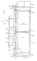
- Figur (3) eine Seitenansicht der Biegemaschine gemäß den Figuren (1) und (2) mit Teilschnittdarstellungen.
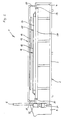
- Figure (1) is a plan view of the bending machine;
- Figure (2) is a front view of the bending machine according to Figure (1) seen from the bending cheek;
- Figure (3) is a side view of the bending machine according to Figures (1) and (2) with partial sectional views.
Die in den Figuren dargestellte Biegemaschine (1) weist einen Maschinenrahmen (2) auf, der im wesentlichen gebildet wird von einem vorderen Rahmenabschnitt (3), zwei seitlichen Rahmenabschnitten (4, 5) und einem rückwärtigen Rahmenabschnitt (6). Die Rahmenabschnitte (3, 4, 5, 6) schließen ein innenseitig im wesentlichen freies Rechteck (7) ein.The bending machine (1) shown in the figures has a machine frame (2) which is essentially formed by a front frame section (3), two side frame sections (4, 5) and a rear frame section (6). The frame sections (3, 4, 5, 6) enclose a substantially free rectangle (7) on the inside.
Wie insbesondere aus den Figuren (2) und (3) zu ersehen ist, ist der seitliche Rahmenabschnitt (5) hochgezogen und dient dabei als Rahmen für eine Acrylglasscheibe (8). Außenseitig an diesen seitlichen Rahmenabschnitt (5) angesetzt ist ein Bedienungspult (9).As can be seen in particular from Figures (2) and (3), the side frame section (5) is pulled up and serves as a frame for an acrylic glass pane (8). An operating panel (9) is attached to the outside of this side frame section (5).
Jeweils benachbart der seitlichen Rahmenabschnitte (5, 6) und parallel dazu verlaufene Führungsstangen (10̸, 11), die sich zwischen dem vorderen Rahmenabschnitt (3) und dem rückwärtigen Rahmenabschnitt (6) erstrecken. Auf diesen Führungsstangen (10̸, 11) ist eine Halteeinrichtung (12) verschieblich in den Richtungen des Doppelpfeils A gelagert. Die Halteeinrichtung (12) besteht aus zwei übereinander angeordneten Klemmleisten (13, 14), von denen die obere Klemmleiste (13) mittels hier nicht näher dargestellter Pneumatikzylinder gegenüber der unteren Klemmleiste (14) anhebbar oder zwecks Festklemmen einer Kunststoffplatte in Richtung auf die untere Klemmleiste (14) absenkbar ist. Die untere Klemmleiste (14) ist mit einem kolbenstangenlosen Positionierzylinder (15) verbunden, der parallel und mittig zu den Führungsstangen (10̸, 11) angeordnet ist und auf einer sich zwischen dem vorderen Rahmenabschnitt (3) und dem rückwärtigen Rahmenabschnitt (6) erstreckenden Stützstrebe (16) angeordnet ist. Der Positionierzylinder (15) wird mittels Druckluft betrieben. Mit der Verschiebung der unteren Klemmleiste (14) wird auch die obere Klemmleiste (13) mitgenommen, d. h. sie behält insoweit ihre Stellung relativ zur unteren Klemmleiste (14) bei.Each adjacent to the side frame sections (5, 6) and parallel to them guide rods (10̸, 11) which extend between the front frame section (3) and the rear frame section (6). On these guide rods (10̸, 11), a holding device (12) is slidably mounted in the directions of the double arrow A. The holding device (12) consists of two stacked clamping strips (13, 14), of which the upper clamping strip (13) can be raised relative to the lower clamping strip (14) by means of pneumatic cylinders (not shown here) or for the purpose of clamping a plastic plate in the direction of the lower clamping strip (14) can be lowered. The lower clamping bar (14) is connected to a rodless positioning cylinder (15) which is arranged parallel and centrally to the guide rods (10̸, 11) and on a support strut extending between the front frame section (3) and the rear frame section (6) (16) is arranged. The positioning cylinder (15) is operated by means of compressed air. With the displacement of the lower terminal block (14), the upper terminal block (13) is taken along, d. H. to this extent it maintains its position relative to the lower terminal block (14).
Mit der unteren Klemmleiste (14) der Halteeinrichtung (12) verbunden ist eine Heizeinrichtung (17). Sie weist zwei sich parallel zu den Klemmleisten (13, 14) erstreckende Heizschwerter (18, 19) auf, die im Abstand zueinander übereinander liegen und an seitlichen Führungsstangen (20̸, 21) vertikal verfahrbar geführt sind. Hierfür sind nicht näher dargestellte Pneumatikzylinder vorgesehen. Auf diese Weise können die Heizschwerter (18, 19) von oben bzw. von unten an eine in der Halteeinrichtung (12) zwischen den Klemmleisten (13, 14) eingeklemmte Kunststoffplatte herangefahren werden. Die Heizschwerter (18, 19) sind mittels elektrischer Energie erhitzbar.A heating device (17) is connected to the lower terminal block (14) of the holding device (12). It has two heating blades (18, 19) which extend parallel to the terminal strips (13, 14) and are at a distance from one another lie one above the other and are guided on the side guide rods (20̸, 21) so that they can move vertically. Pneumatic cylinders, not shown, are provided for this. In this way, the heating blades (18, 19) can be moved from above or from below to a plastic plate clamped in the holding device (12) between the terminal strips (13, 14). The heating blades (18, 19) can be heated by means of electrical energy.
Wie sich insbesondere aus Figur (3) ergibt, sind die Führungsstangen (20̸, 21) untenseitig an einer horizontalen Traverse (22) befestigt, welche über einen vertikalen Träger (23) und einen horizontalen Träger (24) mit der Unterseite der unteren Klemmleiste (14) verbunden ist. Beim Verfahren der Halteeinrichtung (12) wird also die Heizeinrichtung (17) mitgenommen, d. h. die Position der Heizschwerter (18, 19) in Bezug auf die Klemmleisten (13, 14) bleibt - abgesehen von ihren Höhenpositionen - gleich.As can be seen particularly from FIG. 14) is connected. When the holding device (12) is moved, the heating device (17) is taken along, ie. H. the position of the heating blades (18, 19) in relation to the terminal strips (13, 14) remains the same - apart from their height positions.
Auf dem vorderen Rahmenabschnitt (3) ist eine Klemmeinrichtung (25) angeordnet. Die Klemmeinrichtung (25) ist im wesentlichen gleich aufgebaut wie die Halteeinrichtung (12), weist also eine obere Klemmleiste (26) und eine untere Klemmleiste (27) auf. Die untere Klemmleiste (27) ist ortsfest angeordnet. Ihre Oberseite liegt auf der gleichen Höhe wie die Oberseite der unteren Klemmleiste (14) der Halteeinrichtung (12). Die obere Klemmleiste (26) der Klemmeinrichtung (25) ist mittels hier nicht näher dargestellten Pneumatikzylindern vertikal verfahrbar. In Offenstellung kann eine Kunststoffplatte zwischen die Klemmleisten (26, 27) geschoben und durch Absenken der oberen Klemmleiste (26) festgeklemmt werden.A clamping device (25) is arranged on the front frame section (3). The clamping device (25) is constructed essentially the same as the holding device (12), that is, it has an upper clamping bar (26) and a lower clamping bar (27). The lower terminal block (27) is arranged in a stationary manner. Its top is at the same height as the top of the lower terminal block (14) of the holding device (12). The upper clamping bar (26) of the clamping device (25) can be moved vertically by means of pneumatic cylinders, not shown here. In the open position, a plastic plate can be pushed between the terminal strips (26, 27) and clamped by lowering the upper terminal strip (26).
Vor der Klemmeinrichtung (25), und zwar vor der unteren Klemmleiste (27), ist eine Biegewange (28) angeordnet. Sie erstreckt sich im wesentlichen über die Breite des Maschinenrahmens (2) und ist in Schwenklagern (29, 30̸) um eine horizontale Achse aus der in Figur (3) gezeigten, horizontalen Stellung in eine vertikale Stellung verschwenkbar. Hierzu dient ein Elektromotor (31), dessen Drehmoment über ein Winkelgetriebe (32) auf die Biegewange (28) übertragen wird. In horizontaler Stellung fluchtet die Oberseite der Biegewange (28) mit den Oberseiten der unteren Klemmleisten (15) bzw. (27) der Halteeinrichtung (12) bzw. der Klemmeinrichtung (25). An der Biegewange (28) ist zusätzlich ein Stützgestell (33) angebracht, das den umzubiegenden Teil der Kunststoffplatte zusätzlich abstützt.A bending cheek (28) is arranged in front of the clamping device (25), namely in front of the lower clamping bar (27). It extends essentially over the width of the machine frame (2) and is in pivot bearings (29, 30̸) about a horizontal axis from the horizontal shown in Figure (3) Position swiveled into a vertical position. An electric motor (31) is used for this purpose, the torque of which is transmitted to the bending beam (28) via an angular gear (32). In the horizontal position, the upper side of the bending beam (28) is aligned with the upper sides of the lower clamping strips (15) or (27) of the holding device (12) or the clamping device (25). A support frame (33) is additionally attached to the bending cheek (28) and supports the part of the plastic plate to be bent.
Mit der gezeigten Biegemaschine (1) gestaltet sich ein Biegevorgang wie folgt.With the shown bending machine (1), a bending process is as follows.
Zunächst wird die Halteeinrichtung (12) vom Bedienungspult (9) her in die gezeigte vordere Endstellung gebracht, um für die Steuereinrichtung eine Null-Lage zu definieren. Die Klemmleisten (13, 14) der Halteeinrichtung (12) und die Klemmleisten (26, 27) der Klemmeinrichtung (25) werden in Offenstellung angehoben. Ferner wird die Biegewange (28) gegenüber der in Figur (3) dargestellten Stellung um 90̸° nach oben verschwenkt, um einen Anschlag zu bilden. Es kann dann eine Kunststoffplatte von hinten zwischen zunächst die Klemmleisten (13, 14) der Halteeinrichtung (12) und dann weiter nach vorn zwischen die Klemmleisten (26, 27) der Klemmeinrichtung (25) eingeschoben werden, bis sie mit ihrer Vorderkante an der Biegewange (28) zur Anlage kommt.First, the holding device (12) is brought from the control panel (9) into the front end position shown in order to define a zero position for the control device. The clamping strips (13, 14) of the holding device (12) and the clamping strips (26, 27) of the clamping device (25) are raised in the open position. Furthermore, the bending beam (28) is pivoted upwards by 90 ° relative to the position shown in FIG. (3) in order to form a stop. A plastic plate can then be inserted from the rear between the clamping strips (13, 14) of the holding device (12) and then further forward between the clamping strips (26, 27) of the clamping device (25) until their front edge touches the bending beam (28) comes to the plant.
In die Steuereinrichtung wird nun der Abstand eingegeben, in dem die Biegelinie zur an der Biegewange (9) anliegenden freien Kante der Kunststoffplatte zu liegen kommen soll. Der weitere Ablauf wird dann entweder von Hand, also halbautomatisch, oder durch entsprechende Programmierung der Steuereinrichtung vollautomatisch gesteuert.The distance at which the bending line is to come to lie against the free edge of the plastic plate resting on the bending cheek (9) is now entered into the control device. The further sequence is then controlled either manually, that is to say semi-automatically, or fully automatically by appropriate programming of the control device.
Zunächst wird die Klemmeinrichtung (25) durch Absenkung der oberen Klemmleiste (26) geschlossen und damit die Kunststoffplatte in ihrer Stellung fixiert. Anschließend wird die Halteeinrichtung (12) in geöffnetem Zustand durch entsprechende Ansteuerung des Positionierzylinders (15) nach hinten, also von der Klemmeinrichtung (25) weg verfahren, und zwar um einen solchen Betrag, daß die Heizschwerter (18, 19) nach dem Anhalten der Halteeinrichtung (12) oberhalb der vorgesehenen Biegelinie zu stehen kommen. Die Kunststoffplatte wird dann durch Absenken der oberen Klemmleiste (13) in der Halteeinrichtung (12) festgeklemmt. Gleichzeitig werden die beiden Heizschwerter (18, 19) einander angenähert, bis sie an der Oberseite bzw. der Unterseite der Kunststoffplatte zur Anlage gekommen sind. Sie erhitzen dann den Kunststoff im Bereich der vorgesehenen Biegelinie so stark, daß er plastifiziert und biegsam wird.First, the clamping device (25) is closed by lowering the upper clamping bar (26) and the plastic plate is thus fixed in its position. Then will move the holding device (12) in the open state by appropriate actuation of the positioning cylinder (15) to the rear, i.e. away from the clamping device (25), by an amount such that the heating swords (18, 19) after stopping the holding device ( 12) come to rest above the intended bending line. The plastic plate is then clamped in the holding device (12) by lowering the upper clamping strip (13). At the same time, the two heating blades (18, 19) are brought closer together until they come to rest on the top or bottom of the plastic plate. You then heat the plastic so strongly in the area of the intended bending line that it becomes plasticized and flexible.
Wenn die Biegelinie genügend stark erhitzt ist, wird die Klemmeinrichtung (25) durch Hochfahren der oberen Klemmleiste (26) geöffnet. Dann wird die Halteeinrichtung (12) durch entsprechende Ansteuerung des Positionierzylinders (15) wieder in Richtung auf die Biegewange (28) verfahren. Gleichzeitig werden die Heizschwerter (18, 19) von der Kunststoffplatte gelöst und so weit nach oben bzw. nach unten verfahren, daß sie beim weiteren Vorfahren der Halteeinrichtung (12) nicht mit der Klemmeinrichtung (25) bzw. der Biegewange (28) kollidieren können. Der horizontale Abstand zwischen den Heizschwertern (18, 19) und den Klemmleisten (13, 14) der Halteeinrichtung (12) ist so bemessen, daß die erhitzte Biegelinie bei Erreichen der vorderen Endstellung der Halteeinrichtung (12) etwa oberhalb der Hinterkante der Biegewange (28) zu liegen kommt.When the bending line is heated sufficiently, the clamping device (25) is opened by raising the upper clamping bar (26). The holding device (12) is then moved again in the direction of the bending cheek (28) by appropriate actuation of the positioning cylinder (15). At the same time, the heating elements (18, 19) are detached from the plastic plate and moved so far up or down that they cannot collide with the clamping device (25) or the bending cheek (28) as the holding device (12) moves forward . The horizontal distance between the heating bars (18, 19) and the terminal strips (13, 14) of the holding device (12) is dimensioned such that the heated bending line when the holding device (12) reaches the front end position approximately above the rear edge of the bending beam (28 ) comes to rest.
Anschließend wird die Klemmeinrichtung (25) durch Absenken der oberen Klemmleiste (26) zugefahren und damit die Kunststoffplatte festgeklemmt. Dann wird der Elektromotor (31) in der Weise angesteuert, daß die Biegewange (28) zusammen mit dem Stützgestell (33) hochgeschwenkt wird. Hierdurch wird der auf der Biegewange (28) aufgeschobene Teil der Kunststoffplatte entsprechend hochgebogen, wobei durch geeignete Eingabe an die Steuereinrichtung jeder beliebige Winkel einstellbar ist.The clamping device (25) is then closed by lowering the upper clamping strip (26) and the plastic plate is thus clamped in place. Then the electric motor (31) is controlled in such a way that the bending beam (28) is pivoted up together with the support frame (33). As a result, the part of the plastic plate pushed onto the bending cheek (28) is bent up accordingly, any angle being adjustable by suitable input to the control device.
Unmittelbar nach Festklemmen der Kunststoffplatte in der Klemmeinrichtung (25), also noch während des Biegevorgangs, wird die Verklemmung der Kunststoffplatte in der Halteeinrichtung (12) durch Hochfahren der oberen Klemmleiste (13) gelöst und die Halteeinrichtung (12) mittels des Positionierzylinders (15) nach hinten verfahren, bis die Heizschwerter (18, 19) wieder mit der nächsten, vorgesehenen Biegelinie fluchten. Der Abstand zur ersten Biegelinie kann durch entsprechende Eingabe in die Steuereinrichtung festgelegt werden, d. h. dieser Abstand kann derselbe sein wie beim ersten Biegevorgang, es kann jedoch auch ein anderer Abstand vorgegeben werden. Nach Anhalten der Halteeinrichtung (12) wird die Kunststoffplatte durch Absenken der oberen Klemmleiste (13) festgeklemmt und werden die Heizschwerter (18, 19) von oben bzw. von unten an die Oberflächen der Kunststoffplatte zur Anlage gebracht.Immediately after the plastic plate has been clamped in the clamping device (25), that is to say during the bending process, the clamping of the plastic plate in the holding device (12) is released by raising the upper clamping bar (13) and the holding device (12) by means of the positioning cylinder (15). Move backwards until the heating elements (18, 19) are aligned again with the next bending line. The distance to the first bending line can be determined by corresponding input in the control device, i. H. this distance can be the same as in the first bending process, but a different distance can also be specified. After the holding device (12) has stopped, the plastic plate is clamped by lowering the upper clamping bar (13) and the heating blades (18, 19) are brought into contact with the surfaces of the plastic plate from above and from below.
Die Ausbildung einer weiteren Biegelinie erfolgt somit während des Biege- und Aushärtvorgangs an der vorangegangenen Biegelinie. Wenn dieser Vorgang abgeschlossen ist und die neue Biegelinie hinreichend erhitzt ist, wiederholt sich der vorbeschriebene Ablauf, d. h. die Halteeinrichtung (12) wird unter Verklemmung der Kunststoffplatte geschlossen und nach Öffnen der Klemmeinrichtung (25) in Richtung auf die Biegewange (28) verfahren, wobei die Heizschwerter (18, 19) von der Kunststoffplatte wegbewegt werden. Nach Erreichen der vorderen Endstellung der Halteeinrichtung (12) schließt sich ein weiterer Biegevorgang in vorbeschriebener Weise an.A further bending line is thus formed during the bending and curing process on the previous bending line. When this process is complete and the new bending line is sufficiently heated, the above-described process is repeated, i.e. H. the holding device (12) is closed by jamming the plastic plate and, after opening the clamping device (25), is moved in the direction of the bending cheek (28), the heating blades (18, 19) being moved away from the plastic plate. After the front end position of the holding device (12) has been reached, a further bending process follows in the manner described above.
Auf diese Weise kann - wenn gewünscht - ein geschlossener Hohlkörper gebildet werden, dessen einzige offene Stelle ein Schlitz ist, der anschließend von einer entsprechenden Schweißeinrichtung geschlossen werden kann.In this way, if desired, a closed hollow body can be formed, the only open point of which is a slot, which can then be closed by a corresponding welding device.
Claims (4)
a) mit einer Biegewange (28) zum Umbiegen des Werkstückes;
b) mit einem Anschlag zur Anlage des vorderen Endes des Werkstückes beim Einlegen in die Biegemaschine (1);
c) mit einer im Maschinenrahmen (2) in und gegen die Transportrichtung des Werkstückes verfahrbaren Heizeinrichtung (17) zum Plastifizieren einer Biegelinie im Werkstück;
d) mit einer der Biegewange (28) benachbarten, zumindest im Betrieb ortsfesten Klemmeinrichtung (25) zum Einklemmen des Werkstückes nahe der Biegelinie bei einem Biegevorgang;
e) mit einer zur Klemmeinrichtung (25) hin und von dieser zurückfahrbaren Halteeinrichtung (12) zum Fixieren des Werkstückes während der Heizphase der Heizeinrichtung (17);
gekennzeichnet durch folgende Merkmale:
f) die Halteeinrichtung (12) ist während des Betriebes der Biegemaschine (1) frei bewegbar;
g) für die Verschiebung der Halteeinrichtung (12) ist ein motorischer Verschiebeantrieb (15) vorgesehen;
h) die Biegemaschine (1) weist eine solche Steuerung auf,
a) with a bending cheek (28) for bending the workpiece;
b) with a stop for abutting the front end of the workpiece when inserting it into the bending machine (1);
c) with a heating device (17) which can be moved in and against the transport direction of the workpiece in the machine frame (2) for plasticizing a bending line in the workpiece;
d) with a clamping device (25) adjacent to the bending beam (28) and at least stationary during operation for clamping the workpiece near the bending line during a bending process;
e) with a holding device (12) which can be retracted towards and from the clamping device (25) for fixing the workpiece during the heating phase of the heating device (17);
characterized by the following features:
f) the holding device (12) is freely movable during the operation of the bending machine (1);
g) for the displacement of the holding device (12) is a motorized displacement drive (15) provided;
h) the bending machine (1) has such a control,
dadurch gekennzeichnet, daß die Heizeinrichtung (17) auf der Halteeinrichtung (12) angeordnet ist.2. Bending machine according to claim 1,
characterized in that the heating device (17) is arranged on the holding device (12).
dadurch gekennzeichnet, daß die Heizeinrichtung (17) auch noch während des Verfahrens in der Halteeinrichtung (12) in Richtung auf die Klemmeinrichtung (25) aktivierbar ist.3. Bending machine according to claim 1 or 2,
characterized in that the heating device (17) can also be activated in the holding device (12) in the direction of the clamping device (25) during the process.
dadurch gekennzeichnet, daß die Halteeinrichtung (12) aus zumindest zwei gegeneinander bewegbaren Klemmleisten (13, 14) besteht.4. Bending machine according to one of claims 1 to 3,
characterized in that the holding device (12) consists of at least two mutually movable clamping strips (13, 14).
Priority Applications (6)
| Application Number | Priority Date | Filing Date | Title |
|---|---|---|---|
| ES89120237T ES2045342T3 (en) | 1989-11-01 | 1989-11-01 | BENDING MACHINE FOR PLASTIC PARTS. |
| AT89120237T ATE89782T1 (en) | 1989-11-01 | 1989-11-01 | BENDING MACHINE. |
| EP89120237A EP0425724B1 (en) | 1989-11-01 | 1989-11-01 | Bending machine |
| DE8989120237T DE58904519D1 (en) | 1989-11-01 | 1989-11-01 | BENDING MACHINE. |
| US07/604,908 US5112210A (en) | 1989-11-01 | 1990-10-31 | Bending machine |
| JP2293788A JP2948651B2 (en) | 1989-11-01 | 1990-11-01 | Bending machine |
Applications Claiming Priority (1)
| Application Number | Priority Date | Filing Date | Title |
|---|---|---|---|
| EP89120237A EP0425724B1 (en) | 1989-11-01 | 1989-11-01 | Bending machine |
Publications (2)
| Publication Number | Publication Date |
|---|---|
| EP0425724A1 true EP0425724A1 (en) | 1991-05-08 |
| EP0425724B1 EP0425724B1 (en) | 1993-05-26 |
Family
ID=8202084
Family Applications (1)
| Application Number | Title | Priority Date | Filing Date |
|---|---|---|---|
| EP89120237A Expired - Lifetime EP0425724B1 (en) | 1989-11-01 | 1989-11-01 | Bending machine |
Country Status (6)
| Country | Link |
|---|---|
| US (1) | US5112210A (en) |
| EP (1) | EP0425724B1 (en) |
| JP (1) | JP2948651B2 (en) |
| AT (1) | ATE89782T1 (en) |
| DE (1) | DE58904519D1 (en) |
| ES (1) | ES2045342T3 (en) |
Cited By (2)
| Publication number | Priority date | Publication date | Assignee | Title |
|---|---|---|---|---|
| EP0834389A2 (en) * | 1996-10-02 | 1998-04-08 | WEGENER GmbH | Welding apparatus for producing tubular articles |
| DE202013103273U1 (en) | 2013-07-22 | 2014-10-23 | Wegener International Gmbh | Bending machine for bending workpieces made of thermoplastic material |
Families Citing this family (6)
| Publication number | Priority date | Publication date | Assignee | Title |
|---|---|---|---|---|
| DE59104977D1 (en) * | 1990-05-10 | 1995-04-27 | Wegener Gmbh | Process for bending plate-shaped workpieces and bending machine for carrying out the process. |
| AUPO703597A0 (en) * | 1997-05-26 | 1997-06-19 | King, Norman Frederick | Sheet forming apparatus |
| DE20116623U1 (en) * | 2001-10-10 | 2002-11-21 | Wegener Gmbh | welding equipment |
| CA2449918A1 (en) * | 2002-11-19 | 2004-05-19 | Vinode Ramnauth | Apparatus and method for moving frameworks between workstations |
| KR101583333B1 (en) * | 2014-09-23 | 2016-01-07 | 황정식 | Bending apparatus for making a bend heater |
| US20220250304A1 (en) * | 2021-02-11 | 2022-08-11 | Timothy Joseph Dipaula | Transportable and portable board bending machine system |
Citations (1)
| Publication number | Priority date | Publication date | Assignee | Title |
|---|---|---|---|---|
| DE3637436A1 (en) * | 1986-11-04 | 1988-05-11 | Wegener Gmbh & Co Kg | Bending machine for processing workpieces of thermoplastic material |
Family Cites Families (9)
| Publication number | Priority date | Publication date | Assignee | Title |
|---|---|---|---|---|
| US2937689A (en) * | 1957-02-08 | 1960-05-24 | Uniflex Engineering Inc | Material bending apparatus |
| US3149376A (en) * | 1963-08-28 | 1964-09-22 | Top Fab Co | Post-forming machine |
| US3888613A (en) * | 1973-08-08 | 1975-06-10 | Steelcase Inc | Apparatus for post forming laminates |
| GB1448478A (en) * | 1973-11-28 | 1976-09-08 | Protocol Eng Ltd | Methods of and apparatus for edge-forming metallic plates |
| SU1017407A1 (en) * | 1982-02-25 | 1983-05-15 | Воронежское Специальное Конструкторское Бюро Кузнечно-Прессовых Машин И Автоматических Линий | Abutment to section bending machine with rotary cross-piece |
| US4557684A (en) * | 1984-10-04 | 1985-12-10 | Didde Graphic Systems Corporation | Bender for synthetic resin printing plates |
| WO1987002618A1 (en) * | 1985-10-24 | 1987-05-07 | Anechoic Systems, Inc. | Plastic bending |
| DE8531749U1 (en) * | 1985-11-09 | 1986-02-20 | Wegener GmbH & Co KG, 5100 Aachen | Welding equipment |
| FR2630356A1 (en) * | 1988-04-20 | 1989-10-27 | Dimeco Alipresse | FOLDING MACHINE |
-
1989
- 1989-11-01 DE DE8989120237T patent/DE58904519D1/en not_active Expired - Fee Related
- 1989-11-01 AT AT89120237T patent/ATE89782T1/en not_active IP Right Cessation
- 1989-11-01 EP EP89120237A patent/EP0425724B1/en not_active Expired - Lifetime
- 1989-11-01 ES ES89120237T patent/ES2045342T3/en not_active Expired - Lifetime
-
1990
- 1990-10-31 US US07/604,908 patent/US5112210A/en not_active Expired - Fee Related
- 1990-11-01 JP JP2293788A patent/JP2948651B2/en not_active Expired - Fee Related
Patent Citations (1)
| Publication number | Priority date | Publication date | Assignee | Title |
|---|---|---|---|---|
| DE3637436A1 (en) * | 1986-11-04 | 1988-05-11 | Wegener Gmbh & Co Kg | Bending machine for processing workpieces of thermoplastic material |
Cited By (4)
| Publication number | Priority date | Publication date | Assignee | Title |
|---|---|---|---|---|
| EP0834389A2 (en) * | 1996-10-02 | 1998-04-08 | WEGENER GmbH | Welding apparatus for producing tubular articles |
| EP0834389A3 (en) * | 1996-10-02 | 1999-08-04 | WEGENER GmbH | Welding apparatus for producing tubular articles |
| DE202013103273U1 (en) | 2013-07-22 | 2014-10-23 | Wegener International Gmbh | Bending machine for bending workpieces made of thermoplastic material |
| EP2829380A1 (en) | 2013-07-22 | 2015-01-28 | Wegener International GmbH | Bending machine for bending workpieces made of thermoplastic |
Also Published As
| Publication number | Publication date |
|---|---|
| US5112210A (en) | 1992-05-12 |
| EP0425724B1 (en) | 1993-05-26 |
| ES2045342T3 (en) | 1994-01-16 |
| DE58904519D1 (en) | 1993-07-01 |
| ATE89782T1 (en) | 1993-06-15 |
| JPH03176121A (en) | 1991-07-31 |
| JP2948651B2 (en) | 1999-09-13 |
Similar Documents
| Publication | Publication Date | Title |
|---|---|---|
| DE2839978C2 (en) | ||
| EP0456121B1 (en) | Method of bending plate-like workpieces and bending machine for carrying out this method | |
| CH678023A5 (en) | ||
| DE4020804A1 (en) | DEVICE AND METHOD FOR WELDING CONNECTING COMPONENTS TO A PIPE | |
| AT514821B1 (en) | Bending press and bending process | |
| EP0425724B1 (en) | Bending machine | |
| DE102018103870A1 (en) | Handling device, method for operating a handling device, workpiece machining system and movement device | |
| EP0249946B1 (en) | Method and device for the fabrication of a spacing frame for insulating glass panes | |
| EP0462961B1 (en) | Apparatus for bending hollow spaces frames | |
| DE3637436C2 (en) | ||
| DE102007043195A1 (en) | Method and device for welding plastic profile bars, stop and heating mirror for such a device | |
| DE2110540A1 (en) | Frame-welder - for plastic frames eg window frames | |
| DE102011113651A1 (en) | Planar organic sheet e.g. knitted fabric element, deforming device for manufacturing fiber composite component, has folding tool folding partial surface region around fold line relative to another partial surface region | |
| CH648774A5 (en) | DEVICE FOR PRODUCING A CURVED CARRIER AND METHOD FOR OPERATING THE DEVICE. | |
| EP2829382A1 (en) | Heating device for the plastification of workpieces made of a thermoplastic material | |
| DE60114695T2 (en) | Wringer and follower tool with such device | |
| DE102017117979A1 (en) | Bending machine for bending rod-shaped or tubular workpieces | |
| EP0426065B1 (en) | Bending machine | |
| DE3539842A1 (en) | Welding device | |
| EP1764177B1 (en) | Apparatus for cutting glazing bars or the like to lenth and method for cutting glazing bars or the like | |
| EP0439665B1 (en) | Welding machine for flat bars | |
| EP1882568B1 (en) | Device and method for moving window frames | |
| EP1377395B1 (en) | Bending machine, especially a bending or folding press, comprising an adjustable lower tool | |
| EP3199369A1 (en) | Method of preforming and rounding a book block | |
| DE202020002598U1 (en) | Bending machine for bending a workpiece from flat material and control unit for such a bending machine |
Legal Events
| Date | Code | Title | Description |
|---|---|---|---|
| PUAI | Public reference made under article 153(3) epc to a published international application that has entered the european phase |
Free format text: ORIGINAL CODE: 0009012 |
|
| 17P | Request for examination filed |
Effective date: 19900810 |
|
| AK | Designated contracting states |
Kind code of ref document: A1 Designated state(s): AT BE CH DE ES FR GB IT LI LU NL SE |
|
| 17Q | First examination report despatched |
Effective date: 19921109 |
|
| GRAA | (expected) grant |
Free format text: ORIGINAL CODE: 0009210 |
|
| AK | Designated contracting states |
Kind code of ref document: B1 Designated state(s): AT BE CH DE ES FR GB IT LI LU NL SE |
|
| REF | Corresponds to: |
Ref document number: 89782 Country of ref document: AT Date of ref document: 19930615 Kind code of ref document: T |
|
| REF | Corresponds to: |
Ref document number: 58904519 Country of ref document: DE Date of ref document: 19930701 |
|
| ET | Fr: translation filed | ||
| GBT | Gb: translation of ep patent filed (gb section 77(6)(a)/1977) |
Effective date: 19930708 |
|
| ITF | It: translation for a ep patent filed |
Owner name: JACOBACCI CASETTA & PERANI S.P.A. |
|
| EPTA | Lu: last paid annual fee | ||
| REG | Reference to a national code |
Ref country code: ES Ref legal event code: FG2A Ref document number: 2045342 Country of ref document: ES Kind code of ref document: T3 |
|
| PLBE | No opposition filed within time limit |
Free format text: ORIGINAL CODE: 0009261 |
|
| STAA | Information on the status of an ep patent application or granted ep patent |
Free format text: STATUS: NO OPPOSITION FILED WITHIN TIME LIMIT |
|
| 26N | No opposition filed | ||
| EAL | Se: european patent in force in sweden |
Ref document number: 89120237.6 |
|
| PGFP | Annual fee paid to national office [announced via postgrant information from national office to epo] |
Ref country code: GB Payment date: 20011116 Year of fee payment: 13 |
|
| PGFP | Annual fee paid to national office [announced via postgrant information from national office to epo] |
Ref country code: FR Payment date: 20011119 Year of fee payment: 13 |
|
| PGFP | Annual fee paid to national office [announced via postgrant information from national office to epo] |
Ref country code: NL Payment date: 20011123 Year of fee payment: 13 Ref country code: LU Payment date: 20011123 Year of fee payment: 13 Ref country code: BE Payment date: 20011123 Year of fee payment: 13 Ref country code: AT Payment date: 20011123 Year of fee payment: 13 |
|
| PGFP | Annual fee paid to national office [announced via postgrant information from national office to epo] |
Ref country code: SE Payment date: 20011126 Year of fee payment: 13 Ref country code: CH Payment date: 20011126 Year of fee payment: 13 |
|
| REG | Reference to a national code |
Ref country code: GB Ref legal event code: IF02 |
|
| PG25 | Lapsed in a contracting state [announced via postgrant information from national office to epo] |
Ref country code: LU Free format text: LAPSE BECAUSE OF NON-PAYMENT OF DUE FEES Effective date: 20021101 Ref country code: GB Free format text: LAPSE BECAUSE OF NON-PAYMENT OF DUE FEES Effective date: 20021101 Ref country code: AT Free format text: LAPSE BECAUSE OF NON-PAYMENT OF DUE FEES Effective date: 20021101 |
|
| PG25 | Lapsed in a contracting state [announced via postgrant information from national office to epo] |
Ref country code: SE Free format text: LAPSE BECAUSE OF NON-PAYMENT OF DUE FEES Effective date: 20021102 |
|
| PGFP | Annual fee paid to national office [announced via postgrant information from national office to epo] |
Ref country code: DE Payment date: 20021122 Year of fee payment: 14 |
|
| PG25 | Lapsed in a contracting state [announced via postgrant information from national office to epo] |
Ref country code: LI Free format text: LAPSE BECAUSE OF NON-PAYMENT OF DUE FEES Effective date: 20021130 Ref country code: CH Free format text: LAPSE BECAUSE OF NON-PAYMENT OF DUE FEES Effective date: 20021130 Ref country code: BE Free format text: LAPSE BECAUSE OF NON-PAYMENT OF DUE FEES Effective date: 20021130 |
|
| PGFP | Annual fee paid to national office [announced via postgrant information from national office to epo] |
Ref country code: ES Payment date: 20021224 Year of fee payment: 14 |
|
| BERE | Be: lapsed |
Owner name: *WEGENER G.M.B.H. Effective date: 20021130 |
|
| PG25 | Lapsed in a contracting state [announced via postgrant information from national office to epo] |
Ref country code: NL Free format text: LAPSE BECAUSE OF NON-PAYMENT OF DUE FEES Effective date: 20030601 |
|
| GBPC | Gb: european patent ceased through non-payment of renewal fee | ||
| EUG | Se: european patent has lapsed | ||
| REG | Reference to a national code |
Ref country code: CH Ref legal event code: PL |
|
| PG25 | Lapsed in a contracting state [announced via postgrant information from national office to epo] |
Ref country code: FR Free format text: LAPSE BECAUSE OF NON-PAYMENT OF DUE FEES Effective date: 20030731 |
|
| NLV4 | Nl: lapsed or anulled due to non-payment of the annual fee |
Effective date: 20030601 |
|
| REG | Reference to a national code |
Ref country code: FR Ref legal event code: ST |
|
| PG25 | Lapsed in a contracting state [announced via postgrant information from national office to epo] |
Ref country code: ES Free format text: LAPSE BECAUSE OF NON-PAYMENT OF DUE FEES Effective date: 20031103 |
|
| PG25 | Lapsed in a contracting state [announced via postgrant information from national office to epo] |
Ref country code: DE Free format text: LAPSE BECAUSE OF NON-PAYMENT OF DUE FEES Effective date: 20040602 |
|
| REG | Reference to a national code |
Ref country code: ES Ref legal event code: FD2A Effective date: 20031103 |
|
| PG25 | Lapsed in a contracting state [announced via postgrant information from national office to epo] |
Ref country code: IT Free format text: LAPSE BECAUSE OF NON-PAYMENT OF DUE FEES;WARNING: LAPSES OF ITALIAN PATENTS WITH EFFECTIVE DATE BEFORE 2007 MAY HAVE OCCURRED AT ANY TIME BEFORE 2007. THE CORRECT EFFECTIVE DATE MAY BE DIFFERENT FROM THE ONE RECORDED. Effective date: 20051101 |