EP0425381B1 - Apparatus for counting and determination of at least one leucocyte-subpopulation - Google Patents
Apparatus for counting and determination of at least one leucocyte-subpopulation Download PDFInfo
- Publication number
- EP0425381B1 EP0425381B1 EP90403006A EP90403006A EP0425381B1 EP 0425381 B1 EP0425381 B1 EP 0425381B1 EP 90403006 A EP90403006 A EP 90403006A EP 90403006 A EP90403006 A EP 90403006A EP 0425381 B1 EP0425381 B1 EP 0425381B1
- Authority
- EP
- European Patent Office
- Prior art keywords
- tank
- cell
- optical
- injection
- nozzle
- Prior art date
- Legal status (The legal status is an assumption and is not a legal conclusion. Google has not performed a legal analysis and makes no representation as to the accuracy of the status listed.)
- Expired - Lifetime
Links
- 230000003287 optical effect Effects 0.000 claims abstract description 47
- 238000005259 measurement Methods 0.000 claims abstract description 31
- 238000002347 injection Methods 0.000 claims abstract description 29
- 239000007924 injection Substances 0.000 claims abstract description 29
- 239000007788 liquid Substances 0.000 claims abstract description 10
- 238000012545 processing Methods 0.000 claims abstract description 6
- 238000002835 absorbance Methods 0.000 claims description 19
- 239000000243 solution Substances 0.000 claims description 13
- 238000004458 analytical method Methods 0.000 claims description 12
- 239000012530 fluid Substances 0.000 claims description 10
- 238000000034 method Methods 0.000 claims description 10
- 230000005684 electric field Effects 0.000 claims description 5
- 238000011144 upstream manufacturing Methods 0.000 claims description 5
- 239000011159 matrix material Substances 0.000 claims description 4
- 239000002245 particle Substances 0.000 claims description 4
- 238000010438 heat treatment Methods 0.000 claims description 2
- 230000001747 exhibiting effect Effects 0.000 claims 2
- 230000001527 leucocytic effect Effects 0.000 claims 2
- 238000004159 blood analysis Methods 0.000 abstract 1
- 239000000470 constituent Substances 0.000 abstract 1
- 210000004027 cell Anatomy 0.000 description 50
- 210000000265 leukocyte Anatomy 0.000 description 30
- 210000004369 blood Anatomy 0.000 description 9
- 239000008280 blood Substances 0.000 description 9
- 239000011521 glass Substances 0.000 description 5
- 238000010521 absorption reaction Methods 0.000 description 4
- 210000000805 cytoplasm Anatomy 0.000 description 3
- 230000000694 effects Effects 0.000 description 3
- 238000002360 preparation method Methods 0.000 description 3
- 230000035945 sensitivity Effects 0.000 description 3
- 239000003153 chemical reaction reagent Substances 0.000 description 2
- 238000004040 coloring Methods 0.000 description 2
- 230000000093 cytochemical effect Effects 0.000 description 2
- 238000001514 detection method Methods 0.000 description 2
- 230000004069 differentiation Effects 0.000 description 2
- 230000002327 eosinophilic effect Effects 0.000 description 2
- 230000004907 flux Effects 0.000 description 2
- 239000008187 granular material Substances 0.000 description 2
- 210000003714 granulocyte Anatomy 0.000 description 2
- 210000004698 lymphocyte Anatomy 0.000 description 2
- 239000000203 mixture Substances 0.000 description 2
- 230000004044 response Effects 0.000 description 2
- 206010018910 Haemolysis Diseases 0.000 description 1
- 238000011481 absorbance measurement Methods 0.000 description 1
- 230000009471 action Effects 0.000 description 1
- 238000013459 approach Methods 0.000 description 1
- 210000003651 basophil Anatomy 0.000 description 1
- 210000000601 blood cell Anatomy 0.000 description 1
- 210000000170 cell membrane Anatomy 0.000 description 1
- 239000003795 chemical substances by application Substances 0.000 description 1
- 239000011248 coating agent Substances 0.000 description 1
- 238000000576 coating method Methods 0.000 description 1
- 239000003086 colorant Substances 0.000 description 1
- 230000009089 cytolysis Effects 0.000 description 1
- 210000000172 cytosol Anatomy 0.000 description 1
- 230000006378 damage Effects 0.000 description 1
- 230000009699 differential effect Effects 0.000 description 1
- 238000010790 dilution Methods 0.000 description 1
- 239000012895 dilution Substances 0.000 description 1
- 239000000428 dust Substances 0.000 description 1
- 210000003979 eosinophil Anatomy 0.000 description 1
- 230000003628 erosive effect Effects 0.000 description 1
- 231100001261 hazardous Toxicity 0.000 description 1
- 230000008588 hemolysis Effects 0.000 description 1
- 230000007774 longterm Effects 0.000 description 1
- 230000002101 lytic effect Effects 0.000 description 1
- 239000012528 membrane Substances 0.000 description 1
- 210000001616 monocyte Anatomy 0.000 description 1
- 210000005087 mononuclear cell Anatomy 0.000 description 1
- 210000000440 neutrophil Anatomy 0.000 description 1
- 238000004204 optical analysis method Methods 0.000 description 1
- 230000009467 reduction Effects 0.000 description 1
- 238000012216 screening Methods 0.000 description 1
- 238000000926 separation method Methods 0.000 description 1
- 239000004575 stone Substances 0.000 description 1
Images

Classifications
-
- A—HUMAN NECESSITIES
- A61—MEDICAL OR VETERINARY SCIENCE; HYGIENE
- A61B—DIAGNOSIS; SURGERY; IDENTIFICATION
- A61B5/00—Measuring for diagnostic purposes; Identification of persons
-
- G—PHYSICS
- G01—MEASURING; TESTING
- G01N—INVESTIGATING OR ANALYSING MATERIALS BY DETERMINING THEIR CHEMICAL OR PHYSICAL PROPERTIES
- G01N15/00—Investigating characteristics of particles; Investigating permeability, pore-volume, or surface-area of porous materials
- G01N15/10—Investigating individual particles
- G01N15/12—Coulter-counters
-
- C—CHEMISTRY; METALLURGY
- C12—BIOCHEMISTRY; BEER; SPIRITS; WINE; VINEGAR; MICROBIOLOGY; ENZYMOLOGY; MUTATION OR GENETIC ENGINEERING
- C12N—MICROORGANISMS OR ENZYMES; COMPOSITIONS THEREOF; PROPAGATING, PRESERVING, OR MAINTAINING MICROORGANISMS; MUTATION OR GENETIC ENGINEERING; CULTURE MEDIA
- C12N1/00—Microorganisms, e.g. protozoa; Compositions thereof; Processes of propagating, maintaining or preserving microorganisms or compositions thereof; Processes of preparing or isolating a composition containing a microorganism; Culture media therefor
- C12N1/34—Processes using foam culture
-
- G01N15/01—
-
- G01N2015/016—
-
- G01N2015/1019—
-
- G01N2015/1024—
-
- G—PHYSICS
- G01—MEASURING; TESTING
- G01N—INVESTIGATING OR ANALYSING MATERIALS BY DETERMINING THEIR CHEMICAL OR PHYSICAL PROPERTIES
- G01N15/00—Investigating characteristics of particles; Investigating permeability, pore-volume, or surface-area of porous materials
- G01N15/10—Investigating individual particles
- G01N15/14—Electro-optical investigation, e.g. flow cytometers
- G01N15/1404—Fluid conditioning in flow cytometers, e.g. flow cells; Supply; Control of flow
- G01N2015/1413—Hydrodynamic focussing
Definitions
- the subject of the invention is the counting and analysis of at least one leukocyte subpopulation and more specifically relates to an apparatus ensuring this identification by optical and electronic measurement.
- the analysis and automatic resistivity counting are based on the principle of passage of a cell in an electric field where a constant current is maintained.
- the resistance that this cell opposes in the field causes an increase in the voltage necessary for the constancy of the current according to Ohm's law.
- the voltage pulse, generated by the passage of this cell is proportional to the opposite resistance, therefore to its volume regardless of shape.
- it is necessary to treat the blood sample beforehand using specific cytochemical agents allowing the partial destruction of the cells, not to be considered in order to obtain a size discrimination. as precise as the treatment is specific.
- the most commonly used method of differentiation with this principle is the so-called "Leukocyte Screening” method, making it possible to obtain an approach to the blood formula in three populations: Lymphocytes, Mononuclear cells and Granulocytes.
- the main part of the analysis is based on the use of a lytic reagent with differential action.
- a lytic reagent with differential action.
- the leukocyte membranes leak the content of the cytoplasm.
- the cells having no granules contained in their cytoplasm are therefore found, with the cytoplasmic membrane coating their nucleus; granulocytes, on the other hand, keep part of the cytosol, their granules partially preventing its escape.
- the major drawback of this method lies in the fact that leukocytes are only differentiated by their final size and that the action of lysis on certain cells, in particular eosinophils and basophils, is not completely controlled, this causing frequently an overlap or even a superposition of populations which make differentiation impossible or very hazardous.
- the analysis and counting of a leukocyte subpopulation by optical methods uses either the principle of measuring optical diffraction, or the principle of measuring optical density of a cell, or a combination of the two. .
- a cell crossing a light ray generates a diffraction of the incident light, the intensity of which at different angles is a function of the size of the cell and the quantity of light absorbed by it.
- An optical collector having at its center a disc with a black background is placed in alignment with the optical path. The transmitted light is stopped by the disc while the diffracted light is collected on a photosensitive sensor whose response is proportional to the diffraction of the cell.
- a cell crossing a light ray generates an absorbance of the incident light.
- the transmitted light is filtered at the wavelength corresponding to the coloring of the cell, then is collected on a photosensitive sensor whose response is proportional to the light absorbed at the specified wavelength.
- Combinations of these principles are used in order to obtain, for the same cell, diffraction and coloring intensity values or diffraction values at different wavelengths, or alternatively diffraction values at different angles. .
- Cell specific discrimination is obtained through specific cytochemistry.
- Apparatuses using these principles suffer from a high sensitivity of optical alignment making the diffraction measurements of relative stability. Many factors also weaken the measurement such as, in particular, the fouling of the reading tank, the sensitivity of the optical parts to atmospheric dust and temperature and the humidity of the room. In addition, the high technicality required for an efficient optical assembly makes the cost of the device unattractive.
- the subject of the invention is therefore an apparatus which avoids the drawbacks inherent in apparatuses applying the above methods and which allows the identification, counting and / or analysis of at least one leukocyte subpopulation and in particular the eosinophilic polymorphonuclear cells.
- the object of the present invention lies in an apparatus for counting and determining at least one leukocyte subpopulation using at least in part a method of analysis and counting by resistivity based on the principle of passage of a cell in an electric field where a constant current providing a signal interpreted in order to obtain information on the volume of the cell passing through this field and using at least part of an optical method consisting in passing a cell through a light ray and collecting the light in an optical collector absorbed by the cell to provide an interpreted signal in order to obtain information on the absorbance of the cell, which device essentially comprises a housing for the injection, inside a measuring tank, of the flow of sample to be analyzed from a supply circuit upstream of the injection box, which tank is crossed by a light beam collected by a sensor and units for collecting and processing the signals supplied by the optical sensor and by the electrodes serving to generate the electric field being provided downstream of the injection housing, characterized in that the sample flow is hydrodynamically sleeved at the inside the tank by two pressurized sleeving liquids
- Document EP-A-0 165 868 discloses an apparatus as described in the preamble of claim 1.
- an external injection nozzle is mounted inside the housing and ends in a calibrated orifice which makes the interior chamber of said nozzle communicate with the tank, for the emission of a first sleeving fluid.
- annular chamber is formed between a conical part of the external injection nozzle and an internal face of the housing; it communicates with the measurement tank and it is supplied with pressurized fluid by at least one conduit.
- an internal injection nozzle is mounted inside the external nozzle and carries an orifice for injecting pressurized fluid from a conduit which opens into a chamber internal to said external nozzle to the right of the calibrated orifice.
- the invention also provides glass walls on either side of the measuring tank, and which are framed by, on one side a lamp and on the other by a sensor which receives the beam emitted by the lamp and focused by optical elements, which has passed through the sleeved flow of the solution to be analyzed, passing into the tank.
- the interpretation of the results provided by the device is advantageously obtained according to the invention by the fact that the information coming from the resistivity measurements are restored on a curve of distribution of sizes making it possible to locate between a low threshold and a high threshold the population main leukocyte, separating stromas and platelets as well as very large particles.
- the information coming from optical measurements is restored by an absorbance distribution curve making it possible to locate between a low threshold and a high threshold the absorbance of leukocytes by separating the populations of poorly absorbing cells as well as the populations of cells with intense absorption. .
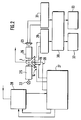
- the device shown in FIG. 1 comprises an injection box 1 of generally cylindrical shape, the upper part of which has a conical profile 2.
- the orifice 3 of the box 1 is capped on at least two opposite sides, with glass walls 4 between which is placed a measuring tank 5 communicating by its base with the injection box and opening at its upper part in a discharge duct 6.
- a plug 7, applied to the glass walls 4, holds the tank 5 and also serves as a support for the end piece 8 of the exhaust duct.
- an external injection nozzle 10 Inside the injection box 1 is mounted in leaktight manner thanks to O-rings 9 an external injection nozzle 10, the upper end 11 of conical shape opens at the base of the measuring tank 5. It is ends with a calibrated orifice 12, for example a hole stone which communicates the inner chamber 18 of said nozzle with the tank 5. It will be noted that between the internal face of the conical part 2 of the injection box, and the face external of the conical end 11 of the nozzle 10, there is provided an annular chamber 13 which also communicates with the measuring tank. This chamber 13 is supplied with pressurized fluid through a conduit 14.
- an internal injection nozzle 16 Inside the external injection nozzle 10 is mounted in a sealed manner by means of O-rings 15 an internal injection nozzle 16 whose upper end 17, also of conical shape, extends into the internal chamber 18 of the external nozzle 10, below the calibrated orifice 12.
- the chamber 18 is itself supplied with pressurized fluid by a conduit 19.
- the internal nozzle is traversed by a conduit 20 allowing the injection of fluid under pressure through the orifice 21 of said nozzle, in line with the calibrated orifice 12.
- the two glass walls 4 are framed by, on one side a lamp 22 and on the other a sensor 23 so that the light beam 24 emitted by the lamp and focused by a suitable optical projector 25 passes through these walls and the measurement tank 5 and are collected by the sensor after passage through another optical system 26.
- the leukocyte solution to be analyzed is injected through the central duct 20 and escapes through the orifice 21 into the chamber 18.
- a liquid under pressure called the sleeving liquid is injected through the duct 19 carrying out a hydrodynamic sheathing of the solution the calibrated orifice 12.
- the sleeved flow coming from this first sleeving therefore crosses the calibrated orifice 12, and is then subjected to a second sleeving carried out by injection of pressurized liquid through the conduit 14 and oriented inside the annular chamber 13.
- This sleeving opens through the orifice 3 in the measuring tank 5, crossed, perpendicular to the flow, of a light beam 24, concentrated and focused on the flow of leukocyte solution.
- the flow of flows in the measuring assembly is done from bottom to top, along a vertical axis, thus avoiding the stagnation of possible bubbles.
- Using double sleeving in this way has a number of advantages.
- the first sleeving achieves perfect centering of the flow of cells in the counting orifice and prevents, by the smoothness of the flow produced and the dilution ratio, the coincident passage of several cells.
- the phenomena of cell deformation due to edge effects as well as rebound of the cells in the sensitivity zone of the counting orifice are also eliminated.
- the second sleeving envelops the flow leaving the orifice and keeps it concentric and stabilized throughout the journey in the optical tank, thus allowing one or more multiple readings at different angles and at different levels.
- This second sleeving makes it possible to use an optical reading tank with a large interior passage eliminating the turbulence of the edge effects and the risk of fouling which would have the effect of making the flow unstable and the optical quality poor.
- Counting and volume detection are ensured by resistivity measurements.
- a current is applied to the terminals of two electrodes situated on either side of the orifice 12, namely an anode constituted by the end piece 8 of the discharge duct and a cathode constituted by the internal nozzle of injection 16.
- the leukocyte counting is carried out when the solution passes through the calibrated orifice 12; each cell passing through the orifice causes an increase in the resistivity of the medium located between the electrodes (8, 16), thus creating a voltage pulse proportional to the volume of the leukocyte.
- Optical detection that is to say the determination of the intensity of the absorption of leukocytes is measured by means of the light beam 24 passing through the tank 5 perpendicular to the flow to be analyzed.
- the light beam is produced by means of the lamp 22, the light energy of which passes through a filter of wavelength corresponding to the absorption of the cell, then of a window is concentrated on a diaphragm behind which is placed the optical projector assembly 25, focused on the flow of leukocyte solution.
- the image of the light window traversed by the flow of solution passes through a collimator then is projected by the other optical collector system 26 onto a photodiode 23 at the terminals of which an amplifier assembly is connected.
- Each leukocyte crossing the light beam causes a reduction in the light intensity measured on the photodiode, proportional to the intensity of its absorption. This results in an electrical pulse across the amplifier, the amplitude of which is itself proportional to the optical density of the leukocyte.
- the calibrated orifice 12 is, as noted in Figure 1, slightly away from the light beam 24, passing through the tank.
- micro-bubbles are naturally eliminated from the counting by the resistance to the vertical flows opposed by the air bubble, thus generating a shift in the resistive and optical counts greater than the standard shift generated by a cell.
- a blood cell must, before the optical measurement, be measured resistively by its passage in the calibrated orifice 12.
- the possible particles contained in the liquid sleeve injected after the counting orifice cannot be taken into account, having not generated a resistive pulse.
- the blood sample Before carrying out the blood injections in the apparatus described above, it is advisable to prepare the blood sample to be analyzed so as to obtain a solution containing mainly the leukocytes in their most natural form possible If necessary the cells can be specifically stained by a specific cytochemical means.
- FIG. 2 shows the processing circuits associated with the apparatus of FIG. 1.
- the box 1 and its associated optical assembly consisting of the lamp 22, the optical projector 25, the optical collector system 26 and the reception photodiode 23.
- the electrodes located in the housing 1 supply signals proportional to the volume of the leukocytes received in an analog circuit 29 for measuring resistivity, signals converted into digital value in a unit 30 for digital processing of information.
- the photodiode 23, for its part, provides signals proportional to the optical density of the leukocytes received in an analog absorbance measurement circuit 31, signals also processed in the unit 30 which then provides graphical 32 or digital 33 results.
- L The set of signals from the same sample is processed using a calculator to determine the number of leukocytes counted in a preset time as well as the relative values of volume and optical density for each of ax.
- each cell When the treated blood solution passes through the measuring device 1, each cell alternately causes a pulse proportional to its size when it passes through the calibrated orifice 12, then a pulse proportional to its absorbance when it passes through the beam. luminous 24.
- a volume value and an absorbance value are memorized and the total results of the volumes and absorbances are distributed according to a histogram.
- the other two populations on the right are considered to be all of the leukocytes in the sample analyzed.
- a distribution curve of the absorbances also presented by way of example in FIG. 4, one obtains a first population on the left made up of weakly or weakly absorbing cells, a second central population made up of cells with medium absorbance, and a third population more on the right, made up of high absorbance cells.
- the invention is not limited to the embodiments described nor to this type of analysis.
- the optical filter with a filter wheel, it is conceivable to liter multiple colors allowing the analysis of other cell types.
- an optical measurement tank According to an alternative embodiment it would be possible to measure the light diffraction of a cell passing through this tank.
- One or more sensors being arranged focused on the tank, in alignment with a light beam passing through it. The information collected, depending on whether the total diffraction or the diffractions at several angles are measured, makes it possible to determine either the relative size of the cell or, in the case of two diffraction measurements at two different angles, the size and relative optical density.
- cytofluorescence measurement it would also be possible to carry out a cytofluorescence measurement by positioning a sensor assembly focused on the measurement tank, 90 degrees from a laser beam passing through it.
- the entire sample preparation must be adapted in order to obtain the desired cell fluorescence.
- the measurements thus obtained make it possible to evaluate the volume of the cell by resistivity, and its fluorescence.
- the current applied to the electrodes and flowing in the counting orifice can be a high frequency current making it possible to obtain, depending on the shape of the pulses collected, an identification on the internal composition of the cell, ie the relative size of the nucleus, more dense compared to the external envelope (cytoplasm) of the cell.
Abstract
Description
L'invention a pour objet le comptage et l'analyse d'au moins une sous-population leucocytaire et concerne plus précisément un appareil assurant cette identification par mesurage optique et électronique.The subject of the invention is the counting and analysis of at least one leukocyte subpopulation and more specifically relates to an apparatus ensuring this identification by optical and electronic measurement.
Indépendament des méthodes manuelles de comptage et d'analyse d'une sous-population leucocytaire qui consistent à visualiser au microscope des échantillons de sang étalés sur une lame, et préalablement colorés, il existe des méthodes automatiques beaucoup plus performantes et précises qui permettent de différencier simultanément plusieurs types de populations sanguines. On connait essentiellement deux types de méthodes d'analyse : les méthodes d'analyse de taille par résistivité et les méthodes d'analyse optique.Independently of the manual methods of counting and analysis of a leukocyte subpopulation which consist in visualizing under the microscope blood samples spread on a slide, and previously colored, there are automatic methods much more efficient and precise which make it possible to differentiate several types of blood populations simultaneously. There are essentially two types of analysis methods: size analysis methods by resistivity and optical analysis methods.
L'analyse et le comptage automatique par résistivité sont basés sur le principe de passage d'une cellule dans un champ électrique où est entretenu un courant constant. La résistance qu'oppose cette cellule dans le champ provoque une augmentation de la tension nécessaire à la constance du courant selon la loi d'Ohm. L'impulsion en tension, générée par le passage de cette cellule, est proportionnelle à la résistance opposée, donc à son volume sans considération de forme. Afin de déterminer une sous-population leucocytaire par ce principe il est nécessaire de traiter préalablement l'échantillon de sang au moyen d'agents cytochimiques spécifiques permettant la destruction partielle des cellules n'étant pas à considérer ceci afin d'obtenir une discrimination de taille aussi précise que le traitement est spécifique.The analysis and automatic resistivity counting are based on the principle of passage of a cell in an electric field where a constant current is maintained. The resistance that this cell opposes in the field causes an increase in the voltage necessary for the constancy of the current according to Ohm's law. The voltage pulse, generated by the passage of this cell, is proportional to the opposite resistance, therefore to its volume regardless of shape. In order to determine a leukocyte subpopulation by this principle, it is necessary to treat the blood sample beforehand using specific cytochemical agents allowing the partial destruction of the cells, not to be considered in order to obtain a size discrimination. as precise as the treatment is specific.
La méthode de différenciation la plus communément utilisée avec ce principe est la méthode dite "Screening Leucocytaire", permettant d'obtenir une approche de la formule sanguine sur trois populations : les Lymphocytes, les cellules Mononucléées et les Granulocytes.The most commonly used method of differentiation with this principle is the so-called "Leukocyte Screening" method, making it possible to obtain an approach to the blood formula in three populations: Lymphocytes, Mononuclear cells and Granulocytes.
L'essentiel de l'analyse repose sur l'utilisation d'une réactif lytique à action différentielle. Par le biais de ce réactif les membranes des leucocytes laissent fuir le contenu du cytoplasme. Les cellules n'ayant pas de granules contenus dans leur cytoplasme se retrouvent donc, avec la membrane cytoplasmique enrobant leur noyau ; les granulocytes, eux, conservent une partie du cytosol, leurs granules empêchant partiellement sa fuite.The main part of the analysis is based on the use of a lytic reagent with differential action. Through this reagent, the leukocyte membranes leak the content of the cytoplasm. The cells having no granules contained in their cytoplasm are therefore found, with the cytoplasmic membrane coating their nucleus; granulocytes, on the other hand, keep part of the cytosol, their granules partially preventing its escape.
L'inconvénient majeur de cette méthode réside dans le fait que les leucocytes ne sont différenciés que par leur taille finale et que l'action de la lyse sur certaines cellules, notamment les éosinophiles et les basophiles, n'est pas maîtrisée totalement, ceci provoquant fréquement un chevauchement voir une superposition des populations qui rendent la différenciation impossible où trés hasardeuse.The major drawback of this method lies in the fact that leukocytes are only differentiated by their final size and that the action of lysis on certain cells, in particular eosinophils and basophils, is not completely controlled, this causing frequently an overlap or even a superposition of populations which make differentiation impossible or very hazardous.
D'un autre coté l'analyse et le comptage d'une sous-population leucocytaire par les méthodes optiques utilisent soit le principe de mesure de diffraction optique, soit le principe de mesure de densité optique d'une cellule, soit une combinaison des deux.On the other hand, the analysis and counting of a leukocyte subpopulation by optical methods uses either the principle of measuring optical diffraction, or the principle of measuring optical density of a cell, or a combination of the two. .
Dans le premier cas, une cellule traversant un rayon lumineux engendre une diffraction de la lumière incidente, dont l'intensité à différents angles est fonction de la taille de la cellule et de la quantité de lumière absorbée par celle-ci. Un collecteur optique ayant en son centre un disque à fond noir est placé dans l'alignement du trajet optique. La lumière transmise est stoppée par le disque tandis que la lumière diffractée est collectée sur un capteur photosensible dont la réponse est proportionnelle à la diffraction de la cellule.In the first case, a cell crossing a light ray generates a diffraction of the incident light, the intensity of which at different angles is a function of the size of the cell and the quantity of light absorbed by it. An optical collector having at its center a disc with a black background is placed in alignment with the optical path. The transmitted light is stopped by the disc while the diffracted light is collected on a photosensitive sensor whose response is proportional to the diffraction of the cell.
Dans le second cas, une cellule traversant un rayon lumineux engendre une absorbance de la lumière incidente. La lumière transmise est filtrée à la longueur d'onde correspondant à la coloration de la cellule, puis est collectée sur un capteur photosensible dont la réponse est proportionnelle à la lumière absorbée à la longeuer d'onde spécifiée.In the second case, a cell crossing a light ray generates an absorbance of the incident light. The transmitted light is filtered at the wavelength corresponding to the coloring of the cell, then is collected on a photosensitive sensor whose response is proportional to the light absorbed at the specified wavelength.
La diffraction cellulaire étant liée à l'absorbance de la cellule ainsi qu'à sa forme, les mesures de volume restent aléatoires, notamment pour ce qui est des leucocytes et il est nécessaire de rendre artificiellement sphériques les cellules à mesurer.On note aussi qu'une cellule de grande taille très colorée sera vue plus petite que sa taille réelle.Cell diffraction being linked to the absorbance of the cell as well as to its shape, the volume measurements remain random, in particular with regard to leukocytes and it is necessary to make the cells to be artificially spherical. It is also noted that a large, very colorful cell will be seen smaller than its actual size.
Des combinaisons de ces principes sont utilisées afin d'obtenir pour une même cellule, des valeurs de diffraction et d'intensité de coloration ou des valeurs de diffraction à des longueurs d'onde différentes, ou encore, des valeurs de diffraction à des angles différents. Par le truchement de cytochimies spécifiques il est obtenu une discrimination cellulaire.Combinations of these principles are used in order to obtain, for the same cell, diffraction and coloring intensity values or diffraction values at different wavelengths, or alternatively diffraction values at different angles. . Cell specific discrimination is obtained through specific cytochemistry.
Les appareillages utilisant ces principes souffrent d'une grande sensibilité de l'alignement optique rendant les mesures de diffraction d'une stabilité relative. De nombreux facteurs fragilisent également la mesure comme, notamment, l'encrassement de la cuve de lecture, la sensibilité des parties optiques aux poussières atmosphériques et à la température et l'hygromètrie du local. En outre, la haute technicité nécessaire à un ensemble optique performant rend le coût de l'appareil peu attractif.Apparatuses using these principles suffer from a high sensitivity of optical alignment making the diffraction measurements of relative stability. Many factors also weaken the measurement such as, in particular, the fouling of the reading tank, the sensitivity of the optical parts to atmospheric dust and temperature and the humidity of the room. In addition, the high technicality required for an efficient optical assembly makes the cost of the device unattractive.
L'invention a donc pour objet un appareil qui évite les inconvénients inhérents aux appareils mettant en application les méthodes précitées et qui permet l'identification, le comptage et/ou l'analyse d'au moins une sous-population leucocytaire et en particulier les polynucléaires éosinophiles.The subject of the invention is therefore an apparatus which avoids the drawbacks inherent in apparatuses applying the above methods and which allows the identification, counting and / or analysis of at least one leukocyte subpopulation and in particular the eosinophilic polymorphonuclear cells.
Ainsi l'objet de la présente invention réside en un appareil pour le comptage et la détermination d'au moins une sous-population leucocytaire utilisant au moins en partie une méthode d'analyse et de comptage par résistivité basée sur le principe de passage d'une cellule dans un champ électrique où est entretenu un courant constant fournissant un signal interprété en vue d'obtenir une information sur le volume de la cellule traversant ce champ et utilisant au moins en partie une méthode optique consistant à faire passer une cellule dans un rayon lumineux et à recueillir dans un collecteur optique la lumière absorbée par la cellule pour fournir un signal interprété en vue d'obtenir une information sur l'absorbance de la cellule, lequel appareil comportant essentiellement un boîtier pour l'injection, à l'intérieur d'une cuve de mesure, du flux d'échantillon à analyser provenant d'un circuit d'alimentation en amont du boîtier d'injection, laquelle cuve est traversée par un faisceau lumineux recueilli par un capteur et des unités de recueil et de traitement des signaux fournis par le capteur optique et par les électrodes servant à engendrer le champ électrique étant prévues en aval du boîtier d'injection, caractérisé en ce que le flux d'échantillon est manchonné hydrodynamiquement à l'intérieur de la cuve par deux liquides de manchonnage sous pression injectés dans la cuve par deux conduits d'alimentation séparés, disposés en amont de la cuve, le second manchonnage enveloppant le premier flux manchonné, et en ce que les deux électrodes pour les mesures de résistivité de la sous-population leucocytaire sont des éléments constitués d'une part, d'une anode formée par l'embout du conduit d'évacuation du flux manchonné de solution sortant de la cuve, et d'autre part, d'une cathode formée par une buse interne d'injection de la solution à analyser.Thus the object of the present invention lies in an apparatus for counting and determining at least one leukocyte subpopulation using at least in part a method of analysis and counting by resistivity based on the principle of passage of a cell in an electric field where a constant current providing a signal interpreted in order to obtain information on the volume of the cell passing through this field and using at least part of an optical method consisting in passing a cell through a light ray and collecting the light in an optical collector absorbed by the cell to provide an interpreted signal in order to obtain information on the absorbance of the cell, which device essentially comprises a housing for the injection, inside a measuring tank, of the flow of sample to be analyzed from a supply circuit upstream of the injection box, which tank is crossed by a light beam collected by a sensor and units for collecting and processing the signals supplied by the optical sensor and by the electrodes serving to generate the electric field being provided downstream of the injection housing, characterized in that the sample flow is hydrodynamically sleeved at the inside the tank by two pressurized sleeving liquids injected into the tank by two separate supply conduits, arranged upstream of the tank, the second sleeving enveloping the first sleeved flow, and in that the two electrodes for the measurements of resistivity of the leukocyte subpopulation are elements consisting on the one hand, of an anode formed by the end-piece of the evacuation duct of the sleeved flow of solution leaving the tank, and on the other hand, of a cathode formed by an internal nozzle for injecting the solution to be analyzed.
Le document EP-A-0 165 868 divulgue un appareil tel que décrit dans le préambule de la revendication 1.Document EP-A-0 165 868 discloses an apparatus as described in the preamble of
Selon une caractéristique de l'invention, une buse externe d'injection est montée à l'intérieur du boitier et se termine par un orifice calibré qui fait communiquer la chambre intérieure de ladite buse avec la cuve, pour l'émission d'un premier liquide de manchonnage.According to a characteristic of the invention, an external injection nozzle is mounted inside the housing and ends in a calibrated orifice which makes the interior chamber of said nozzle communicate with the tank, for the emission of a first sleeving fluid.
Avantageusement, une chambre annulaire est ménagée entre une partie conique de la buse externe d'injection et une face interne du boitier ; elle communique avec la cuve de mesure et elle est alimentée en fluide sous pression par au moins un conduit.Advantageously, an annular chamber is formed between a conical part of the external injection nozzle and an internal face of the housing; it communicates with the measurement tank and it is supplied with pressurized fluid by at least one conduit.
Selon une autre caractéristique particulière de l'invention, une buse interne d'injection est montée à l'intérieur de la buse externe et porte un orifice d'injection de fluide sous pression provenant d'un conduit qui débouche dans une chambre intérieure à ladite buse externe au droit de l'orifice calibré.According to another particular characteristic of the invention, an internal injection nozzle is mounted inside the external nozzle and carries an orifice for injecting pressurized fluid from a conduit which opens into a chamber internal to said external nozzle to the right of the calibrated orifice.
L'invention prévoit également des parois de verre de part et d'autre de la cuve de mesure, et qui sont encadrées par, d'un coté une lampe et de l'autre par un capteur qui reçoit le faisceau émis par la lampe et focalisé par des éléments optiques, qui a traversé le flux manchonné de la solution à analyser, passant dans la cuve.The invention also provides glass walls on either side of the measuring tank, and which are framed by, on one side a lamp and on the other by a sensor which receives the beam emitted by the lamp and focused by optical elements, which has passed through the sleeved flow of the solution to be analyzed, passing into the tank.
L'interprétation des résultats fournis par l'appareil est avantageusement obtenue selon l'invention par le fait que les informations provenant des mesures de résistivité sont restituées sur une courbe de répartition des tailles permettant de localiser entre un seuil bas et un seuil haut la population principale de leucocytes, en séparant les stromas et plaquettes ainsi que les particules de trés grande taille.The interpretation of the results provided by the device is advantageously obtained according to the invention by the fact that the information coming from the resistivity measurements are restored on a curve of distribution of sizes making it possible to locate between a low threshold and a high threshold the population main leukocyte, separating stromas and platelets as well as very large particles.
De même les informations provenant des mesures optiques sont restituées par une courbe de répartition des absorbances permettant de localiser entre un seuil bas et un seuil haut l'absorbance des leucocytes en séparant les populations de cellules peu absorbantes ainsi que les populations de cellules à absorption intense.Similarly, the information coming from optical measurements is restored by an absorbance distribution curve making it possible to locate between a low threshold and a high threshold the absorbance of leukocytes by separating the populations of poorly absorbing cells as well as the populations of cells with intense absorption. .
De plus il apparait également avantageux que les informations provenant des mesures de résistivité et des mesures optiques puissent être resituées dans une représentation graphique en matrice, permettant de visualiser des contours représentatifs de la répartition des populations.In addition, it also appears advantageous that the information coming from resistivity measurements and optical measurements can be reproduced in a graphic representation in matrix, making it possible to visualize contours representative of the distribution of the populations.
D'autres caractéristiques et avantages de l'invention serant mieux perçus à la lecute de la description qui va suivre qui fait référence aux dessins annexés qui représentent
- Figure 1 une vue en coupe de boitier d'injection.
- Figure 2 une vue schématique des circuits de préparation et de traitement associés à l'appareil.
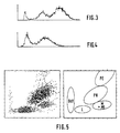
- Figure 3 une courbe de répartition des tailles des leucocytes analysés.
- Figure 4 une courbe de répartition des absorbances des leucocytes analysés.
- Figure 5 une représentation graphique matricielle des contours représentatifs de la répartition des populations.
- Figure 1 a sectional view of the injection box.
- Figure 2 a schematic view of the preparation and processing circuits associated with the device.
- Figure 3 is a curve showing the size distribution of the leukocytes analyzed.
- Figure 4 a distribution curve of the absorbances of the analyzed leukocytes.
- Figure 5 a matrix graphic representation of the contours representative of the distribution of populations.
L'appareil représenté à la figure 1 comporte un boitier d'injection 1 de forme générale cylindrique dont la partie supérieure présente un profil conique 2. L'orifice 3 du boitier 1 est coiffé sur au moins deux faces opposées, de parois de verre 4 entre lesquelles est disposée une cuve de mesure 5 communiquant par sa base avec le boitier d'injection et débouchant à sa partie supérieure dans un conduit d'évacuation 6. Un bouchon 7, appliqué sur les parois de verre 4, maintient la cuve 5 et sert également de support à l'embout 8 du conduit d'évacuation.The device shown in FIG. 1 comprises an
A l'intérieur du boitier d'injection 1 est montée de façon étanche grâce à des joints toriques 9 une buse externe d'injection 10 dont l'extrémité supérieure 11 de forme conique débouche à la base de la cuve de mesure 5. Elle se termine par un orifice calibré 12, par exemple une pierre à trou qui fait communiquer la chambre intérieure 18 de ladite buse avec la cuve 5. On notera qu'entre la face interne de la partie conique 2 du boitier d'injection, et la face externe de l'extrémité conique 11 de la buse 10, se trouve ménagée une chambre annulaire 13 qui communique également avec la cuve de mesure. Cette chambre 13 est alimentée en fluide sous pression par un conduit 14.Inside the
A l'intérieur de la buse externe d'injection 10 est montée de façon étanche grâce à des joints toriques 15 une buse interne d'injection 16 dont l'extrémité supérieure 17, également de forme conique s'étend dans la chambre intérieure 18 de la buse externe 10, au dessous de l'orifice calibré 12. La chambre 18 est elle-même alimentée en fluide sous pression par un conduit 19. De même la buse interne est traversée par un conduit 20 permettant l'injection de fluide sous pression par l'orifice 21 de ladite buse, au droit de l'orifice calibré 12. Les deux parois de verre 4 sont encadrées par, d'un coté une lampe 22 et de l'autre un capteur 23 de telle sorte que le faisceau lumineux 24 émis par la lampe et focalisé par un projecteur optique approprié 25 traverse ces parois et la cuve de mesure 5 et soient recueillis par le capteur après passage au travers d'un autre système optique 26.Inside the
La solution de leucocytes à analyser est injectée par le conduit central 20 et s'échappe par l'orifice 21 dans la chambre 18. Simultanément on injecte par le conduit 19 un liquide sous pression dit liquide de manchonnage réalisant un gainage hydrodynamique de la solution dans l'orifice calibré 12. Le flux manchonné provenant de ce premier manchonnage traverse donc l'orifice calibré 12, et se trouve alors soumis à un deuxième manchonnage réalisé par injection de liquide sous pression par le conduit 14 et orienté à l'intérieur de la chambre annulaire 13. Ce manchonnage débouche par l'orifice 3 dans la cuve de mesure 5, traversée, perpendiculairement au flux, d'un faisceau lumineux 24, concentré et focalisé sur le flux de solution de leucocytes. La circulation des flux dans l'ensemble de mesure se fait du bas vers le haut, selon un axe vertical, évitant ainsi la stagnation d'éventuelles bulles. Le fait d'utiliser ainsi un double manchonnage présente un certain nombre d'avantages.The leukocyte solution to be analyzed is injected through the
Le premier manchonnage réalise un centrage parfait du flux de cellules dans l'orifice de comptage et interdit, de par la finesse du flux réalisé et du ratio de dilution, le passage coïncidant de plusieurs cellules. Les phénomènes de déformation des cellules dus aux effets de bord ainsi que de rebond des cellules dans la zone de sensibilité de l'orifice de comptage, sont également éliminés.The first sleeving achieves perfect centering of the flow of cells in the counting orifice and prevents, by the smoothness of the flow produced and the dilution ratio, the coincident passage of several cells. The phenomena of cell deformation due to edge effects as well as rebound of the cells in the sensitivity zone of the counting orifice are also eliminated.
Le second manchonnage enveloppe le flux sortant de l'orifice et le maintient concentrique et stabilisé pendant tout le trajet dans la cuve optique, autorisant ainsi une ou plusieurs lectures à différents angles et à différents niveaux.The second sleeving envelops the flow leaving the orifice and keeps it concentric and stabilized throughout the journey in the optical tank, thus allowing one or more multiple readings at different angles and at different levels.
Ce second manchonnage permet d'utiliser une cuve de lecture optique de large passage intérieur éliminant les turbulences des effets de bord et le risque d'encrassement qui auraient pour effets de rendre le flux instable et la qualité optique médiocre.This second sleeving makes it possible to use an optical reading tank with a large interior passage eliminating the turbulence of the edge effects and the risk of fouling which would have the effect of making the flow unstable and the optical quality poor.
Le fait d'utiliser une cuve de larges dimensions élimine également la vitesse du flux sur ces parois; cette vitesse étant faible, l'érosion des parois de verre,- que l'on peut constater à long terme sur les cuves optiques capillaires dans lesquelles la vitesse du manchon doit être égale à la vitesse du flux - est diminuée.The fact of using a large tank also eliminates the speed of the flow on these walls; this speed being low, the erosion of the glass walls - which can be observed in the long term on capillary optical tanks in which the speed of the sleeve must be equal to the speed of the flow - is reduced.
Le cumul de ces caractéristiques ajouté au fait que le positionnement du flux est réalisé par le positionnement de l'orifice de comptage, rend l'alignement du faisceau optique sur le flux extrêmement stable. Un démontage de la cuve ne justifie nullement un réglage optique après son remontage.The combination of these characteristics added to the fact that the positioning of the flux is achieved by the positioning of the counting orifice, makes the alignment of the optical beam on the flux extremely stable. Dismantling the tank in no way justifies an optical adjustment after reassembly.
Le comptage et la détection du volume sont assurés par des mesures de résistivité. A cet effet on applique un courant aux bornes de deux électrodes situées de part et d'autre de l'orifice 12, à savoir une anode constituée par l'embout 8 du conduit d'évacuation et une cathode constituée de la buse interne d'injection 16. Le comptage des leucocytes est réalisé lors du passage de la solution dans l'orifice calibré 12 ; chaque cellule passant dans l'orifice provoque une augmentation de la résistivité du milieu situé entre les électrodes (8, 16), créant ainsi une impulsion en tension proportionnelle au volume du leucocyte.Counting and volume detection are ensured by resistivity measurements. To this end, a current is applied to the terminals of two electrodes situated on either side of the
La détection optique c'est à dire la détermination de l'intensité de l'absorpiton des leucocytes est mesurée au moyen du faisceau lumineux 24 traversant la cuve 5 perpendiculairement au flux à analyser. Le faisceau lumineux est réalisé au moyen de la lampe 22, dont l'énergie lumineuse passant au travers d'un filtre de longueur d'onde correspondant à l'absorption de la cellule, puis d'une fenêtre est concentrée sur un diaphragme derrière lequel est placé l'ensemble projecteur optique 25, focalisé sur le flux de solution de leucocytes. L'image de la fenêtre lumineuse traversée par le flux de solution, passe par un collimateur puis est projetée par l'autre système optique collecteur 26 sur une photodiode 23 aux bornes de laquelle est connecté un montage amplificateur.Optical detection, that is to say the determination of the intensity of the absorption of leukocytes is measured by means of the
Chaque leucocyte traversant le faisceau lumineux, provoque une réduction de l'intensité lumineuse mesurée sur la photodiode, proportionnelle à l'intensité de son absorption. Cela se traduit par une impulsion électrique aux bornes de l'amplificateur, dont l'amplitude est elle-même, proportionnelle à la densité optique du leucocyte.Each leukocyte crossing the light beam causes a reduction in the light intensity measured on the photodiode, proportional to the intensity of its absorption. This results in an electrical pulse across the amplifier, the amplitude of which is itself proportional to the optical density of the leukocyte.
L'orifice calibré 12 se trouve, comme on le remarque à la figure 1, légèrement à l'écart du faisceau lumineux 24, traversant la cuve.The calibrated
On notera que cette distance séparant l'orifice 12 du point de focalisation de mesure optique engendre un décalage temporel des impulsions résistives et optiques.It will be noted that this distance separating the
La constance de ce décalage est contrôlée et permet de mettre en évidence la moindre chute de performance de la fluidique.The constancy of this offset is controlled and makes it possible to highlight the slightest drop in fluidic performance.
Les micro-bulles sont naturellement éliminées du comptage par la résistance aux flux vertical qu'oppose la bulle d'air, engendrant ainsi un décalage dans les comptages résistifs et optiques supérieur au décalage standard engendré par une cellule.The micro-bubbles are naturally eliminated from the counting by the resistance to the vertical flows opposed by the air bubble, thus generating a shift in the resistive and optical counts greater than the standard shift generated by a cell.
Pour être prise en compte, une cellule sanguine doit, préalablement à la mesure optique, être mesurée de manière résistive par son passage dans l'orifice calibré 12. Ainsi les éventuelles particules contenues dans le manchon liquide injecté après l'orifice de comptage ne peuvent être prises en compte, n'ayant pas généré d'impulsion résistive.To be taken into account, a blood cell must, before the optical measurement, be measured resistively by its passage in the calibrated
Avant de procéder aux injections de sang dans l'appraeil décrit plus haut, il convient de préparer l'échantillon de sang à analyser de manière à obtenir une solution contenant principalement les leucocytes dans leur forme la plus naturelle possible Si nécessaire les cellules peuvent être spécifiquement colorées par un moyen cytochimique déterminé .Before carrying out the blood injections in the apparatus described above, it is advisable to prepare the blood sample to be analyzed so as to obtain a solution containing mainly the leukocytes in their most natural form possible If necessary the cells can be specifically stained by a specific cytochemical means.
On a représenté à la figure 2 les circuits de traitement associés à l'appareil de la figure 1. On a schématisé le boitier 1 et son ensemble optique associé constitué de la lampe 22, du projecteur optique 25, du système optique collecteur 26 et la photodiode de réception 23. Le sang admis dans le boitier 1 par conduit 20, ainsi que les fluides de manchonnage admis par les conduits 14 et 19 subissent une préparation et proviennent d'une ensemble de distribution hydraulique 27, lui-même alimenté par un échantillon de sang provenant d'une unité 28 de mélange et de chauffage. Les électrodes localisées dans le boitier 1 fournissent des signaux proportionnels au volume des leucocytes reçus dans un circuit analogique 29 de mesure de résistivité, signaux convertis en valeur numérique dans une unité 30 de traitement numérique des informations. La photodiode 23, de son coté, fournit des signaux proportionnels à la densité optique des leucocytes reçus dans un circuit analogique 31 de mesure d'absorbance, signaux également traités dans l'unité 30 qui fournit ensuite des résultats graphiques 32 ou numériques 33. L'ensemble des signaux d'un même échantillon est traité au moyen d'un calculateur afin de déterminer le nombre de leucocytes comptés dans un temps préétabli ainsi que des valeurs relatives de volume et de densité optique pour chacun d'eax.FIG. 2 shows the processing circuits associated with the apparatus of FIG. 1. The
Quand la solution de sang traité passe dans l'appareil de mesure 1, chaque cellule provoque alternativement une impulsion proportionnelle à sa taille lorsqu'elle passe dans l'orifice calibré 12, puis une impulsion proportionnelle à son absorbance lors de son passage dans le faisceau lumineux 24. Pour une même cellule, une valeur de volume et une valeur d'absorbance sont mémorisées et les résultats totaux des volumes et des absorbances sont répartis selon un histogramme.When the treated blood solution passes through the measuring
Sur une courbe de répartition des tailles présentée à titre d'exemple à la figure 3, avec en ordonnée la représentation quantitative et en abscisse le volume, on note la présence de trois populations distinctes. La population la plus à gauche, donc de particules de petites tailles, est considérée comme étant le bruit de fond composé principalement des stromas, résultants de l'hémolyse, et des plaquettes.On a size distribution curve presented by way of example in FIG. 3, with the quantitative representation on the ordinate and the volume on the abscissa, the presence of three distinct populations is noted. The leftmost population, therefore of particles of small sizes, is considered to be the background noise composed mainly of stromas, resulting from hemolysis, and platelets.
Les deux autres populations de droite sont considérées comme étant la totalité des leucocytes de l'échantillon analysé. Sur une courbe de répartition des absorbances présentée aussi à titre d'exemple à la figure 4, on obtient une première population à gauche constituée de cellules peu ou faiblement absorbantes, une seconde population centrale constituée de cellules à absorbance moyenne, et une troisième population plus à droite constituée de cellules de forte absorbance.The other two populations on the right are considered to be all of the leukocytes in the sample analyzed. On a distribution curve of the absorbances also presented by way of example in FIG. 4, one obtains a first population on the left made up of weakly or weakly absorbing cells, a second central population made up of cells with medium absorbance, and a third population more on the right, made up of high absorbance cells.
Sur une représentation graphique matricielle presentée également à titre d'exemple à la figure 5, on observe la répartition des populations en taille selon l'axe des X et en absorbance selon l'axe des Y. Cette représentation permet l'étude des leucocytes par un logiciel de taxonomie, le positionnement de seuils permettant la séparation d'au moins une population de leucocytes, Bdf représentant les bruits de fond (stomas + plaquettes) :
L : Lymphocytes
M : Monocytes
PN : Polynucléaires neutrophiles
PE : Polynucléaires éosinophiles
PB : Polynucléaires basophiles.On a matrix graphic representation also presented by way of example in FIG. 5, the distribution of the populations in size is observed along the X axis and in absorbance along the Y axis. This representation allows the study of leukocytes by taxonomy software, the positioning of thresholds allowing the separation of at least one population of leukocytes, Bdf representing the background noises (stomas + platelets):
L: Lymphocytes
M: Monocytes
PN: Neutrophil polymorphonuclear
PE: Eosinophilic polymorphonuclear
PB: Basophilic polymorphonuclear cells.
L'invention ne se limite pas aux modes de réalisation décrits ni à ce type d'analyses. Notamment on peut envisager, en remplaçant le filtre optique par une roue à filtres, de litre des colorations multiples autorisant l'analyse d'autres types cellulaires.The invention is not limited to the embodiments described nor to this type of analysis. In particular, by replacing the optical filter with a filter wheel, it is conceivable to liter multiple colors allowing the analysis of other cell types.
De plus, on a parlé précédemment d'une cuve de mesure optique .Selon une variante de réalisation il serait possible de mesurer la diffraction lumineuse d'une cellule traversant cette cuve. Un ou plusieurs capteurs étant disposés focalisés sur la cuve, dans l'alignement d'un rayon lumineux traversant celle-ci. Les informations recueillies, selon que l'on mesure la diffraction totale ou les diffractions à plusieurs angles, permettent la détermination soit de la taille relative de la cellule, soit, dans le cas deu deux mesures de diffraction à deux angles différents, de la taille et de la densité optique relative.In addition, we previously talked about an optical measurement tank. According to an alternative embodiment it would be possible to measure the light diffraction of a cell passing through this tank. One or more sensors being arranged focused on the tank, in alignment with a light beam passing through it. The information collected, depending on whether the total diffraction or the diffractions at several angles are measured, makes it possible to determine either the relative size of the cell or, in the case of two diffraction measurements at two different angles, the size and relative optical density.
En variante, il serait possible également de réaliser une mesure de cytofluorescence en positionnant un ensemble capteur focalisé sur la cuve de mesure, à 90 degrés d'un rayon laser la traversant. L'ensemble de préparation de l'échantillon devant être adapté afin d'obtenir la fluorescence cellulaire recherchée. Les mesures ainsi obtenues permettent d'évaluer le volume de la cellule par résistivité, et sa fluorescence.As a variant, it would also be possible to carry out a cytofluorescence measurement by positioning a sensor assembly focused on the measurement tank, 90 degrees from a laser beam passing through it. The entire sample preparation must be adapted in order to obtain the desired cell fluorescence. The measurements thus obtained make it possible to evaluate the volume of the cell by resistivity, and its fluorescence.
En variante encore, et toujours selon le principe même de l'ensemble de mesure, le courant appliqué aux électrodes et circulant dans l'orifice de comptage, peut être un courant à haute fréquence permettant d'obtenir, selon la forme des impulsions recueillies, une identification sur la composition interne de la cellule, soit la taille relative du noyau, plus dense par rapport à l'enveloppe externe (cytoplasme) de la cellule.In another variant, and always according to the very principle of the measuring assembly, the current applied to the electrodes and flowing in the counting orifice, can be a high frequency current making it possible to obtain, depending on the shape of the pulses collected, an identification on the internal composition of the cell, ie the relative size of the nucleus, more dense compared to the external envelope (cytoplasm) of the cell.
La combinaison des variantes exposées ci-dessus permet d'obtenir pour un flux de cellules traversant la cuve de mesure, à la fois le volume global de chaque cellule, associé à sa densité optique et/ou sa fluorescence, ainsi que des informations sur sa composition interne, à savoir la taille relative de son noyau et/ou sa forme relative ou sa régularité.The combination of the variants set out above makes it possible to obtain, for a flow of cells passing through the measuring cell, both the overall volume of each cell, associated with its optical density and / or its fluorescence, as well as information on its internal composition, namely the relative size of its nucleus and / or its relative shape or regularity.
Claims (9)
- Apparatus for counting and determining at least one leucocytic sub-population using at least in part an analysis and counting method by resistivity based on the principle of a cell passing through an electric field where a constant current is maintained delivering a signal which is interpreted so as to obtain information about the volume of the cell passing through this field and using at least in part an optical method which consists in causing a cell to pass through a light ray and collecting in an optical reader the light absorbed by the cell so as to provide a signal interpreted in order to obtain information about the absorbance of the cell, said apparatus comprising essentially a case (1) for injecting inside a measurement tank (5) the flow of sample to be analysed, which is supplied from a feed circuit upstream of the injection case (1), and said tank (5) is crossed by a light beam collected by a sensor (23) and units (29, 30, 31) for collecting and processing the signals delivered by the optical sensor (23) and by the electrodes used to generate the electric field which are provided upstream of the injection case (1),
characterised in that the sample flow is sleeved hydrodynamically inside the tank by two pressurised sleeving liquids injected into the tank (5) through two separate feed ducts (14, 19) arranged upstream of the tank, the second sleeving enveloping the first sleeved flow, and in that the two electrodes for measurement of the resistivity of the leucocytic sub-population are elements constituted, on the one hand, by an anode formed by the end piece (8) of the discharge duct (6) for the sleeved flow of solution leaving the tank (5), and on the other hand by a cathode formed by an internal nozzle (16) for injection of the solution to be analysed. - Apparatus according to claim 1, characterised in that an external injection nozzle (10) ending in a calibrated orifice (12) is mounted inside the case (1) and causes the internal chamber (18) of said nozzle to communicate with the tank (5), for the emission of the first sleeving liquid, and in that an annular chamber (13) which also communicates with the measurement tank (5) is incorporated between a conical part (11) of said external injection nozzle (10) and an internal face of the injection case (1), said chamber being fed with pressurised fluid through a duct (14), for the emission of the second sleeving liquid.
- Apparatus according to claims 1 and 2, characterised in that an internal injection nozzle (16) is mounted inside the external nozzle (10) and has an orifice (21) for the injection of pressurised fluid coming from a duct (20) which opens into a chamber (18) inside said external nozzle in line with the calibrated orifice (12).
- Apparatus according to claim 1, using a measurement tank surrounded, on one side, by a lamp and, on the other, by a sensor which receives the light beam emitted by the lamp and focused by optical elements, characterised in that the measurement tank (5) has a wide internal passage so that the doubly sleeved flow remains concentric and stabilised during the whole of its travel through the tank.
- Apparatus according to claim 1, characterised in that a sensor assembly is positioned, focused on the measurement tank (5), at 90° from a laser ray passing through it, for carrying out a cytofluorescence measurement.
- Apparatus according to claim 1, characterised in that the liquid to be analysed and the sleeving fluids come from a hydraulic distribution assembly (27) fed by a sample from a mixing and heating unit (28).
- Apparatus according to claim 1, characterised in that the information coming from the resistivity measurements is restored in the form of a curve of distribution of the volumes for localising, between at least a low threshold and a high threshold, the main leucocyte population, by separating the stromata and platelets as well as the very large sized particles.
- Apparatus according to claim 1, characterised in that the information coming from the optical measurements is restored by means of an absorbance distribution curve for localising, between a low threshold and a high threshold, the absorbance of the leucocytes by eliminating the cell populations exhibiting little absorbance and the cell populations exhibiting intense absorbance.
- Apparatus according to claims 1, 7 and 8, characterised in that the information coming from the resistivity measurements and optical measurements is restored in a graphic representation in matrix form, for displaying the contours representative of the distribution of the populations.
Applications Claiming Priority (2)
| Application Number | Priority Date | Filing Date | Title |
|---|---|---|---|
| FR8914120 | 1989-10-27 | ||
| FR8914120A FR2653885B1 (en) | 1989-10-27 | 1989-10-27 | APPARATUS FOR COUNTING AND DETERMINING AT LEAST ONE LEUKOCYTAIC SUB-POPULATION. |
Publications (2)
| Publication Number | Publication Date |
|---|---|
| EP0425381A1 EP0425381A1 (en) | 1991-05-02 |
| EP0425381B1 true EP0425381B1 (en) | 1995-02-22 |
Family
ID=9386856
Family Applications (1)
| Application Number | Title | Priority Date | Filing Date |
|---|---|---|---|
| EP90403006A Expired - Lifetime EP0425381B1 (en) | 1989-10-27 | 1990-10-25 | Apparatus for counting and determination of at least one leucocyte-subpopulation |
Country Status (17)
| Country | Link |
|---|---|
| US (1) | US5138181A (en) |
| EP (1) | EP0425381B1 (en) |
| JP (1) | JP3069795B2 (en) |
| KR (1) | KR0164208B1 (en) |
| AT (1) | ATE118888T1 (en) |
| AU (1) | AU628679B2 (en) |
| CA (1) | CA2028474C (en) |
| DE (1) | DE69017144T2 (en) |
| DK (1) | DK0425381T3 (en) |
| ES (1) | ES2071061T3 (en) |
| FI (1) | FI102324B1 (en) |
| FR (1) | FR2653885B1 (en) |
| HK (1) | HK53796A (en) |
| IE (1) | IE67378B1 (en) |
| NO (1) | NO312487B1 (en) |
| PT (1) | PT95709B (en) |
| ZA (1) | ZA908601B (en) |
Cited By (1)
| Publication number | Priority date | Publication date | Assignee | Title |
|---|---|---|---|---|
| FR3138211A1 (en) | 2022-07-25 | 2024-01-26 | Horiba Abx Sas | Device for counting and differentiating particles from a sample stream |
Families Citing this family (48)
| Publication number | Priority date | Publication date | Assignee | Title |
|---|---|---|---|---|
| JP3232145B2 (en) * | 1991-12-27 | 2001-11-26 | シスメックス株式会社 | Reticulocyte measurement method |
| JP3052665B2 (en) * | 1993-01-26 | 2000-06-19 | 株式会社日立製作所 | Flow cell device |
| US5601234A (en) * | 1994-08-01 | 1997-02-11 | Abbott Laboratories | Fluid nozzle and method of introducing a fluid |
| US5530540A (en) * | 1994-08-03 | 1996-06-25 | Wyatt Technology Corporation | Light scattering measurement cell for very small volumes |
| FR2733835B1 (en) * | 1995-05-03 | 1997-07-18 | Hycel Groupe Lisabio | METHOD AND DEVICE FOR DETECTING THE LYSIS POINT OF RED CELLS |
| FR2734637B1 (en) * | 1995-05-24 | 1997-08-14 | Abx Sa | DEVICE FOR OPTICAL INSPECTION OF A FLUID, PARTICULARLY FOR HEMATOLOGICAL ANALYSIS |
| FR2734636B1 (en) * | 1995-05-24 | 1997-07-11 | Abx Sa | DEVICE FOR OPTICAL INSPECTION OF A FLUID, PARTICULARLY FOR HEMATOLOGICAL ANALYSIS |
| JP3587607B2 (en) * | 1995-12-22 | 2004-11-10 | シスメックス株式会社 | Particle measuring apparatus and method |
| EP2264428B1 (en) | 1997-01-31 | 2017-05-03 | Xy, Llc | Optical apparatus with focussing reflector for converging radiation onto a flow of particles |
| US6149867A (en) | 1997-12-31 | 2000-11-21 | Xy, Inc. | Sheath fluids and collection systems for sex-specific cytometer sorting of sperm |
| KR100346118B1 (en) * | 1998-07-13 | 2002-10-25 | 삼성전자 주식회사 | Device and method for beleting electrical noise of cover in hard driver |
| US6473171B1 (en) * | 1999-01-15 | 2002-10-29 | Coors Brewing Company | Biocompatible apparatus for ultrasensitive and rapid detection of contaminants in liquids |
| US6507400B1 (en) | 1999-02-27 | 2003-01-14 | Mwi, Inc. | Optical system for multi-part differential particle discrimination and an apparatus using the same |
| US7208265B1 (en) | 1999-11-24 | 2007-04-24 | Xy, Inc. | Method of cryopreserving selected sperm cells |
| US6646742B1 (en) | 2000-02-19 | 2003-11-11 | Mwi, Inc. | Optical device and method for multi-angle laser light scatter |
| AU2002220018A1 (en) | 2000-11-29 | 2002-06-11 | Colorado State University | System for in-vitro fertilization with spermatozoa separated into x-chromosome and y-chromosome bearing populations |
| US7713687B2 (en) | 2000-11-29 | 2010-05-11 | Xy, Inc. | System to separate frozen-thawed spermatozoa into x-chromosome bearing and y-chromosome bearing populations |
| US8486618B2 (en) | 2002-08-01 | 2013-07-16 | Xy, Llc | Heterogeneous inseminate system |
| AU2003265362B2 (en) | 2002-08-01 | 2009-11-05 | Xy, Llc. | Low pressure sperm cell separation system |
| BRPI0313476B1 (en) | 2002-08-15 | 2015-06-23 | Xy Llc | High resolution flow cytometer |
| US7169548B2 (en) | 2002-09-13 | 2007-01-30 | Xy, Inc. | Sperm cell processing and preservation systems |
| US8323984B2 (en) * | 2002-12-19 | 2012-12-04 | Beckman Coulter, Inc. | Method and apparatus for mixing blood samples for cell analysis |
| DE602004024874D1 (en) | 2003-03-28 | 2010-02-11 | Inguran Llc | EASTER-ASSORTED TIERSPERMIES |
| DE10320870A1 (en) * | 2003-05-09 | 2004-12-09 | Evotec Technologies Gmbh | Particle injector for a cell sorter |
| AU2004242121B2 (en) | 2003-05-15 | 2010-06-24 | Xy, Llc. | Efficient haploid cell sorting for flow cytometer systems |
| ES2397678T3 (en) | 2004-03-29 | 2013-03-08 | Inguran, Llc | Sperm suspensions for classification in enriched populations carrying the X or Y chromosome |
| MX2007000888A (en) | 2004-07-22 | 2007-04-02 | Monsanto Technology Llc | Process for enriching a population of sperm cells. |
| FR2878032B1 (en) * | 2004-11-18 | 2007-03-02 | Horiba Abx Sa Sa | DEVICE FOR INSPECTING A UNIFORM ILLUMINATION FLUID BY MEANS OF A CONFORMING LIGHT GUIDE |
| US7355696B2 (en) * | 2005-02-01 | 2008-04-08 | Arryx, Inc | Method and apparatus for sorting cells |
| US7580120B2 (en) * | 2005-04-07 | 2009-08-25 | Sysmex Corporation | Blood analyzer, sample analyzer, and flow cytometer |
| WO2008061058A2 (en) * | 2006-11-10 | 2008-05-22 | Luminex Corporation | Flow cytometer and fluidic line assembly with multiple injection needles |
| US7804594B2 (en) * | 2006-12-29 | 2010-09-28 | Abbott Laboratories, Inc. | Method and apparatus for rapidly counting and identifying biological particles in a flow stream |
| JP4994920B2 (en) * | 2007-02-01 | 2012-08-08 | シスメックス株式会社 | Sample analyzer |
| EP1953526B1 (en) | 2007-02-01 | 2017-08-30 | Sysmex Corporation | Hematological analyzer, method for analyzing body fluid and computer program product |
| EP3680643A1 (en) | 2007-02-01 | 2020-07-15 | Sysmex Corporation | Sample analyzer and computer program product |
| US8159670B2 (en) | 2007-11-05 | 2012-04-17 | Abbott Laboratories | Method and apparatus for rapidly counting and identifying biological particles in a flow stream |
| FR2933192B1 (en) | 2008-06-25 | 2010-09-17 | Horiba Abx Sas | DEVICE AND METHOD FOR ELECTRO OPTICAL MEASUREMENT FOR CLASSIFYING AND COUNTING MICROSCOPIC ELEMENTS. |
| FR2939199B1 (en) | 2008-12-02 | 2011-02-11 | C2 Diagnostics | METHOD AND DEVICE FOR FLOW CYTOMETRY WITHOUT SAGING FLUID |
| CA2759392A1 (en) | 2009-04-27 | 2010-11-04 | Abbott Laboratories | Method for discriminating red blood cells from white blood cells by using forward scattering from a laser in an automated hematology analyzer |
| FR2956207B1 (en) * | 2010-02-10 | 2012-05-04 | Horiba Abx Sas | DEVICE AND METHOD FOR MULTIPARAMETRIC MEASUREMENTS OF MICROPARTICLES IN A FLUID |
| US9097704B2 (en) | 2010-05-05 | 2015-08-04 | Abbott Laboratories | Method for hematology analysis |
| FR2971337B1 (en) | 2011-02-04 | 2013-03-01 | Horiba Abx Sas | DEVICE AND METHOD FOR MULTIPARAMETRIC MEASUREMENTS OF MICROPARTICLES IN A FLUID |
| CN103575637B (en) * | 2013-11-12 | 2016-02-10 | 桂林优利特医疗电子有限公司 | A kind of sheath flow impedance, optical synchronous counting assembly |
| FR3022998B1 (en) * | 2014-06-30 | 2016-07-15 | Alain Rousseau Techniques & Innovations Arteion | SYSTEM AND ASSEMBLY FOR FLOW CYTOMETRY, ANALYSIS DEVICE COMPRISING SUCH A CYTOMETRY ASSEMBLY AND ASSEMBLY COMPRISING SUCH A CYTOMETRY SYSTEM |
| FR3034198B1 (en) | 2015-03-26 | 2019-05-31 | C2 Diagnostics | HYDROFOCUS APPARATUS WITH SINGLE ANALYSIS SOLUTION |
| FR3034520B1 (en) | 2015-04-02 | 2020-02-14 | Horiba Abx Sas | PARTICLE COUNTING DEVICE |
| FR3068469B1 (en) | 2017-06-28 | 2020-09-11 | Diagdev | MEASURING TANK FOR ENUMERATION AND / OR CHARACTERIZATION OF CELLS |
| FR3106408A1 (en) | 2020-01-17 | 2021-07-23 | Horiba Abx Sas | Electro-optical device for flow measurements |
Family Cites Families (11)
| Publication number | Priority date | Publication date | Assignee | Title |
|---|---|---|---|---|
| BE793185A (en) * | 1971-12-23 | 1973-04-16 | Atomic Energy Commission | APPARATUS FOR QUICKLY ANALYZING AND SORTING PARTICLES SUCH AS BIOLOGICAL CELLS |
| US3781112A (en) * | 1972-12-15 | 1973-12-25 | Technicon Instr | Method and apparatus for analysis of leukocytes using light scattered by each leukocyte at absorbing and non-absorbing wavelength |
| DE2943116C2 (en) * | 1979-10-25 | 1986-06-19 | Gesellschaft für Strahlen- und Umweltforschung mbH, 8000 München | Device for flow cytometric reaction and / or diffusion measurement |
| US4348107A (en) * | 1980-07-18 | 1982-09-07 | Coulter Electronics, Inc. | Orifice inside optical element |
| US4515274A (en) * | 1981-12-02 | 1985-05-07 | Coulter Corporation | Particle analyzing and sorting apparatus |
| CH651930A5 (en) * | 1983-03-24 | 1985-10-15 | Coulter Corp | Apparatus for analysis and sorting of particles |
| JPS59184841A (en) * | 1983-04-05 | 1984-10-20 | ベクトン・デイツキンソン・アンド・カンパニ− | Method and device for discriminating sub-class of leukocyte in sample |
| FR2566543B1 (en) * | 1984-06-20 | 1988-02-26 | Commissariat Energie Atomique | HIGH COLLECTION AND CYTOFLUORIMETER OPTICAL DEVICE USING THE SAME |
| JPS63262565A (en) * | 1987-04-20 | 1988-10-28 | Hitachi Ltd | Flow cell |
| FR2621123B1 (en) * | 1987-09-30 | 1989-12-01 | Commissariat Energie Atomique | METHOD FOR MANUFACTURING A DEVICE FOR OPTICAL ANALYSIS OF A MICROPARTICLE STREAM AND APPLICATION TO THE MANUFACTURE OF A CYTOFLUORIMETER |
| US5030002A (en) * | 1989-08-11 | 1991-07-09 | Becton, Dickinson And Company | Method and apparatus for sorting particles with a moving catcher tube |
-
1989
- 1989-10-27 FR FR8914120A patent/FR2653885B1/en not_active Expired - Fee Related
-
1990
- 1990-10-24 CA CA002028474A patent/CA2028474C/en not_active Expired - Fee Related
- 1990-10-25 ES ES90403006T patent/ES2071061T3/en not_active Expired - Lifetime
- 1990-10-25 IE IE384790A patent/IE67378B1/en not_active IP Right Cessation
- 1990-10-25 DE DE69017144T patent/DE69017144T2/en not_active Expired - Fee Related
- 1990-10-25 DK DK90403006.1T patent/DK0425381T3/en active
- 1990-10-25 AT AT90403006T patent/ATE118888T1/en not_active IP Right Cessation
- 1990-10-25 EP EP90403006A patent/EP0425381B1/en not_active Expired - Lifetime
- 1990-10-26 US US07/602,952 patent/US5138181A/en not_active Expired - Lifetime
- 1990-10-26 PT PT95709A patent/PT95709B/en not_active IP Right Cessation
- 1990-10-26 AU AU65502/90A patent/AU628679B2/en not_active Ceased
- 1990-10-26 ZA ZA908601A patent/ZA908601B/en unknown
- 1990-10-26 KR KR1019900017192A patent/KR0164208B1/en not_active IP Right Cessation
- 1990-10-26 NO NO19904640A patent/NO312487B1/en unknown
- 1990-10-26 FI FI905296A patent/FI102324B1/en not_active IP Right Cessation
- 1990-10-29 JP JP2293503A patent/JP3069795B2/en not_active Expired - Fee Related
-
1996
- 1996-03-28 HK HK53796A patent/HK53796A/en not_active IP Right Cessation
Cited By (2)
| Publication number | Priority date | Publication date | Assignee | Title |
|---|---|---|---|---|
| FR3138211A1 (en) | 2022-07-25 | 2024-01-26 | Horiba Abx Sas | Device for counting and differentiating particles from a sample stream |
| WO2024023430A1 (en) | 2022-07-25 | 2024-02-01 | Horiba Abx Sas | Device for counting and differentiating the particles of a sample flow |
Also Published As
| Publication number | Publication date |
|---|---|
| CA2028474C (en) | 2002-06-11 |
| DK0425381T3 (en) | 1995-05-01 |
| KR910007483A (en) | 1991-05-30 |
| HK53796A (en) | 1996-04-03 |
| DE69017144D1 (en) | 1995-03-30 |
| ZA908601B (en) | 1991-08-28 |
| FI102324B (en) | 1998-11-13 |
| DE69017144T2 (en) | 1995-06-22 |
| ES2071061T3 (en) | 1995-06-16 |
| FI102324B1 (en) | 1998-11-13 |
| US5138181A (en) | 1992-08-11 |
| KR0164208B1 (en) | 1999-01-15 |
| IE903847A1 (en) | 1991-05-08 |
| NO904640D0 (en) | 1990-10-26 |
| JPH03170843A (en) | 1991-07-24 |
| FR2653885B1 (en) | 1994-01-14 |
| NO312487B1 (en) | 2002-05-13 |
| IE67378B1 (en) | 1996-03-20 |
| EP0425381A1 (en) | 1991-05-02 |
| AU6550290A (en) | 1991-05-02 |
| ATE118888T1 (en) | 1995-03-15 |
| NO904640L (en) | 1991-04-29 |
| JP3069795B2 (en) | 2000-07-24 |
| PT95709B (en) | 1998-07-31 |
| FR2653885A1 (en) | 1991-05-03 |
| AU628679B2 (en) | 1992-09-17 |
| CA2028474A1 (en) | 1991-04-28 |
| PT95709A (en) | 1991-09-13 |
| FI905296A0 (en) | 1990-10-26 |
Similar Documents
| Publication | Publication Date | Title |
|---|---|---|
| EP0425381B1 (en) | Apparatus for counting and determination of at least one leucocyte-subpopulation | |
| CA1144280A (en) | Automated method for cell volume determination | |
| US3788744A (en) | Method and apparatus for photoanalysis | |
| EP2671063B1 (en) | Device and method for multiparametric measurements of microparticles in a fluid | |
| WO2010063936A9 (en) | Sheath-fluid-free flow cytometry method and device | |
| EP0737307A1 (en) | Liquid flow cytometer | |
| GB1578695A (en) | Apparatus for measuring particles dispersed in a liquid | |
| FR2938649A1 (en) | METHOD AND SYSTEM FOR ANALYSIS OF SOLID PARTICLES IN A MEDIUM | |
| CA3068599C (en) | Measuring cuvette for counting and/or characterizing cells | |
| CN103278432B (en) | A kind of pick-up unit of integrity of filtration membranes and detection method thereof | |
| Eisert | High resolution optics combined with high spatial reproducibility in flow | |
| Latkoczy et al. | Development of a mobile fast-screening laser-induced breakdown detection (LIBD) system for field-based measurements of nanometre sized particles in aqueous solutions | |
| WO2021144545A1 (en) | Electro-optical device for taking measurements of flow | |
| FR3138211A1 (en) | Device for counting and differentiating particles from a sample stream | |
| WO2023118708A1 (en) | Element for an optical measurement system | |
| FR2604257A1 (en) | INSTRUMENT FOR MEASURING ULTRA-FINE PARTICLES | |
| JPS6171336A (en) | Grain-size measuring apparatus | |
| CN111504888A (en) | Particle analysis and sorting device and method | |
| FR2777350A1 (en) | Maintaining optical system on cytometric head free from bubbles, useful to allow measurements to continue without halt for maintenance |
Legal Events
| Date | Code | Title | Description |
|---|---|---|---|
| PUAI | Public reference made under article 153(3) epc to a published international application that has entered the european phase |
Free format text: ORIGINAL CODE: 0009012 |
|
| AK | Designated contracting states |
Kind code of ref document: A1 Designated state(s): AT BE CH DE DK ES FR GB GR IT LI LU NL SE |
|
| 17P | Request for examination filed |
Effective date: 19911003 |
|
| 17Q | First examination report despatched |
Effective date: 19930712 |
|
| GRAA | (expected) grant |
Free format text: ORIGINAL CODE: 0009210 |
|
| AK | Designated contracting states |
Kind code of ref document: B1 Designated state(s): AT BE CH DE DK ES FR GB GR IT LI LU NL SE |
|
| REF | Corresponds to: |
Ref document number: 118888 Country of ref document: AT Date of ref document: 19950315 Kind code of ref document: T |
|
| REF | Corresponds to: |
Ref document number: 69017144 Country of ref document: DE Date of ref document: 19950330 |
|
| GBT | Gb: translation of ep patent filed (gb section 77(6)(a)/1977) |
Effective date: 19950328 |
|
| REG | Reference to a national code |
Ref country code: DK Ref legal event code: T3 |
|
| ITF | It: translation for a ep patent filed |
Owner name: STUDIO TORTA SOCIETA' SEMPLICE |
|
| REG | Reference to a national code |
Ref country code: ES Ref legal event code: FG2A Ref document number: 2071061 Country of ref document: ES Kind code of ref document: T3 |
|
| REG | Reference to a national code |
Ref country code: GR Ref legal event code: FG4A Free format text: 3016015 |
|
| PLBE | No opposition filed within time limit |
Free format text: ORIGINAL CODE: 0009261 |
|
| STAA | Information on the status of an ep patent application or granted ep patent |
Free format text: STATUS: NO OPPOSITION FILED WITHIN TIME LIMIT |
|
| 26N | No opposition filed | ||
| REG | Reference to a national code |
Ref country code: GB Ref legal event code: IF02 |
|
| PGFP | Annual fee paid to national office [announced via postgrant information from national office to epo] |
Ref country code: NL Payment date: 20050930 Year of fee payment: 16 |
|
| PGFP | Annual fee paid to national office [announced via postgrant information from national office to epo] |
Ref country code: SE Payment date: 20051005 Year of fee payment: 16 Ref country code: AT Payment date: 20051005 Year of fee payment: 16 |
|
| PGFP | Annual fee paid to national office [announced via postgrant information from national office to epo] |
Ref country code: GR Payment date: 20051007 Year of fee payment: 16 |
|
| PGFP | Annual fee paid to national office [announced via postgrant information from national office to epo] |
Ref country code: GB Payment date: 20051014 Year of fee payment: 16 |
|
| PGFP | Annual fee paid to national office [announced via postgrant information from national office to epo] |
Ref country code: DK Payment date: 20051018 Year of fee payment: 16 |
|
| PGFP | Annual fee paid to national office [announced via postgrant information from national office to epo] |
Ref country code: BE Payment date: 20051021 Year of fee payment: 16 |
|
| PGFP | Annual fee paid to national office [announced via postgrant information from national office to epo] |
Ref country code: FR Payment date: 20051026 Year of fee payment: 16 |
|
| PGFP | Annual fee paid to national office [announced via postgrant information from national office to epo] |
Ref country code: ES Payment date: 20051027 Year of fee payment: 16 |
|
| PGFP | Annual fee paid to national office [announced via postgrant information from national office to epo] |
Ref country code: LU Payment date: 20051028 Year of fee payment: 16 |
|
| PGFP | Annual fee paid to national office [announced via postgrant information from national office to epo] |
Ref country code: CH Payment date: 20051107 Year of fee payment: 16 |
|
| PGFP | Annual fee paid to national office [announced via postgrant information from national office to epo] |
Ref country code: DE Payment date: 20051222 Year of fee payment: 16 |
|
| PG25 | Lapsed in a contracting state [announced via postgrant information from national office to epo] |
Ref country code: AT Free format text: LAPSE BECAUSE OF NON-PAYMENT OF DUE FEES Effective date: 20061025 |
|
| PG25 | Lapsed in a contracting state [announced via postgrant information from national office to epo] |
Ref country code: SE Free format text: LAPSE BECAUSE OF NON-PAYMENT OF DUE FEES Effective date: 20061026 |
|
| PG25 | Lapsed in a contracting state [announced via postgrant information from national office to epo] |
Ref country code: LI Free format text: LAPSE BECAUSE OF NON-PAYMENT OF DUE FEES Effective date: 20061031 Ref country code: DK Free format text: LAPSE BECAUSE OF NON-PAYMENT OF DUE FEES Effective date: 20061031 Ref country code: CH Free format text: LAPSE BECAUSE OF NON-PAYMENT OF DUE FEES Effective date: 20061031 |
|
| PGFP | Annual fee paid to national office [announced via postgrant information from national office to epo] |
Ref country code: IT Payment date: 20061031 Year of fee payment: 17 |
|
| PG25 | Lapsed in a contracting state [announced via postgrant information from national office to epo] |
Ref country code: DE Free format text: LAPSE BECAUSE OF NON-PAYMENT OF DUE FEES Effective date: 20070501 Ref country code: NL Free format text: LAPSE BECAUSE OF NON-PAYMENT OF DUE FEES Effective date: 20070501 |
|
| REG | Reference to a national code |
Ref country code: CH Ref legal event code: PL |
|
| EUG | Se: european patent has lapsed | ||
| GBPC | Gb: european patent ceased through non-payment of renewal fee |
Effective date: 20061025 |
|
| NLV4 | Nl: lapsed or anulled due to non-payment of the annual fee |
Effective date: 20070501 |
|
| REG | Reference to a national code |
Ref country code: FR Ref legal event code: ST Effective date: 20070629 |
|
| PG25 | Lapsed in a contracting state [announced via postgrant information from national office to epo] |
Ref country code: GB Free format text: LAPSE BECAUSE OF NON-PAYMENT OF DUE FEES Effective date: 20061025 |
|
| BERE | Be: lapsed |
Owner name: *ABX Effective date: 20061031 |
|
| REG | Reference to a national code |
Ref country code: ES Ref legal event code: FD2A Effective date: 20061026 |
|
| PG25 | Lapsed in a contracting state [announced via postgrant information from national office to epo] |
Ref country code: FR Free format text: LAPSE BECAUSE OF NON-PAYMENT OF DUE FEES Effective date: 20061031 Ref country code: ES Free format text: LAPSE BECAUSE OF NON-PAYMENT OF DUE FEES Effective date: 20061026 |
|
| PG25 | Lapsed in a contracting state [announced via postgrant information from national office to epo] |
Ref country code: LU Free format text: LAPSE BECAUSE OF NON-PAYMENT OF DUE FEES Effective date: 20061025 |
|
| PG25 | Lapsed in a contracting state [announced via postgrant information from national office to epo] |
Ref country code: GR Free format text: LAPSE BECAUSE OF NON-PAYMENT OF DUE FEES Effective date: 20070503 |
|
| PG25 | Lapsed in a contracting state [announced via postgrant information from national office to epo] |
Ref country code: BE Free format text: LAPSE BECAUSE OF FAILURE TO SUBMIT A TRANSLATION OF THE DESCRIPTION OR TO PAY THE FEE WITHIN THE PRESCRIBED TIME-LIMIT Effective date: 20061031 Ref country code: IT Free format text: LAPSE BECAUSE OF NON-PAYMENT OF DUE FEES Effective date: 20071025 |