EP0424302B1 - Method for controlling the multi-frame transmission on token ring networks - Google Patents
Method for controlling the multi-frame transmission on token ring networks Download PDFInfo
- Publication number
- EP0424302B1 EP0424302B1 EP90480153A EP90480153A EP0424302B1 EP 0424302 B1 EP0424302 B1 EP 0424302B1 EP 90480153 A EP90480153 A EP 90480153A EP 90480153 A EP90480153 A EP 90480153A EP 0424302 B1 EP0424302 B1 EP 0424302B1
- Authority
- EP
- European Patent Office
- Prior art keywords
- frame
- transmitted
- counter
- transmit
- contents
- Prior art date
- Legal status (The legal status is an assumption and is not a legal conclusion. Google has not performed a legal analysis and makes no representation as to the accuracy of the status listed.)
- Expired - Lifetime
Links
Images


Classifications
-
- H—ELECTRICITY
- H04—ELECTRIC COMMUNICATION TECHNIQUE
- H04L—TRANSMISSION OF DIGITAL INFORMATION, e.g. TELEGRAPHIC COMMUNICATION
- H04L12/00—Data switching networks
- H04L12/28—Data switching networks characterised by path configuration, e.g. LAN [Local Area Networks] or WAN [Wide Area Networks]
- H04L12/42—Loop networks
- H04L12/427—Loop networks with decentralised control
- H04L12/433—Loop networks with decentralised control with asynchronous transmission, e.g. token ring, register insertion
Definitions
- This invention relates to communication networks in general and more particularly to a method and apparatus for controlling the multi-frame transmission and providing optimal utilization of the transmission bandwidth when a station is capable of transmitting multiple frames onto the ring before releasing the token.
- a transmit station can send frames using either a single frame or a multi-frame mode.
- single frame mode a station sends only one frame for each usable token that it acquires.
- multi-frame mode a station sends multiple frames per usable token.
- the maximum number of frames a station can transmit per usable token is limited by the token holding timer which is specified in the applicable standard, i.e., either the IEEE 802.5 standard for token rings or the ANSI standard X3T9.5 for fiber distributed data interface (FDDI).
- One way of managing the transmission of a multi-frame transmit sequence is for the transmit station to transmit its frame queue until it gets to the last frame in the queue. If, at that time, the THT has not expired, the transmitter terminates the transmit sequence by marking the intermediate frame bit (I-bit) in the ending delimiter of the current frame as the last frame. If the transmit frame sequence is not completed at the end of the THT window, the transmit station aborts the partially transmitted last frame and releases a token.
- I-bit intermediate frame bit
- IBM Technical Diclosure Bulletin, Vol. 26, Noll, 4/84 discloses a technique which enable a station on a token ring communication system to transmit a plurality of frames without releasing a free token.
- Each station is fitted with a Token Holding Timer which is used to indicate to the transmitting station when to terminate its transmission. It shows the maximum number of bytes that a station is allowed to transmit. If there is a pending message, and its size is less than or equal to the THT, then that message may be sent. If ther is a pending message whose size is greater than the THT, than the message is inhibited.
- the transmit station always looks ahead at the length of the next frame to be transmitted.
- the transmitter sets a counter identified as the total transmit length counter (TTLEN) which is used to manage the maximum amount of data bytes that the transmitter can send within the THT time window.
- TTLEN total transmit length counter
- the transmitter then decrements the TTLEN on each data byte that it transmits.
- the transmitter compares the length of the next frame (NFLEN) with the residual count value in the TTLEN counter.
- the transmitter terminates the transmit sequence by marking the current frame as the last frame in the I-bit of the ending delimiter in the frame trailer, and then releasing the token if in early token release mode. If the TTLEN counter value is greater than the next frame length, the transmitter marks the current frame as an intermediate frame and continues to transmit the next frame.
- the last frame decision algorithm is performed before transmitting the frame check sequence (FCS) of each frame transmitted. The last frame decision algorithm does not waste any ring bandwidth if the total transmit queue exceeds the THT time window.
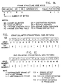
- FIGS 1A-1E illustrate the frame structure and delimiters used in conjunction with the IEEE 802.5 protocol standard.
- Figure 2 illustrates a block diagram implementation of this invention.
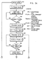
- Figures 3A-3B illustrate a flow chart for the last frame decision algorithm of this invention.
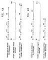
- Figures 4A-4B illustrate scenarios demonstrating the two different last frame ending conditions handled by the last frame decision algorithm.
- the invention will be particularly described with respect to the frame structure used in the IEEE 802.5 protocol.
- a person skilled in the art will readily be able to apply the last frame decision algorithm described herein to the ANSI X3T9.5 protocol for FDDI or any other protocol using a ring topology.
- the frame structure and delimiter patterns of the IEEE 802.5 token ring protocol are shown in Figures 1A-1E.
- the token ring frame structure is used here to illustrate the operation and timing of the last frame decision algorithm relative to the different fields of the frame.
- Figure 1A shows the overall frame structure which contains a starting delimiter (SD), access control field (AC), frame control field (FC), destination address (DA), source address (SA), information field, frame check sequence (FCS), ending delimiter (ED), and frame status field (FS).
- SD delimiter
- AC access control field
- FC frame control field
- DA destination address
- SA source address
- FCS frame check sequence
- ED ending delimiter
- FS frame status field
- the frame header consists of the SD, AC, FC, DA and SA fields.
- the frame trailer consists of the FCS, ED and FS fields.
- Figures 1B and 1C show the starting delimiter and ending delimiter data patterns respectively. In IEEE 802.5 token ring application, only the first six bits of the ending delimiter are considered in decoding the pattern; the last two are ignored.
- the I-bit which is used to indicate whether a frame is an intermediate frame or the last frame, follows in the first half of bit number 6.
- the I-bit is set by the transmitter to indicate whether the transmit frame is the last frame or an intermediate frame. A zero in the I-bit indicates the last frame. A one in the I-bit indicates an intermediate frame.
- Figure 1D shows the bit pattern of the access control byte.
- Figure 1E shows the bit pattern for a token which consists of a starting delimiter, access control byte and ending delimiter.
- FIG. 2 A block diagram of the apparatus implementing the last frame decision algorithm is shown in Figure 2.
- Incoming ring data is first converted from Differential Manchester code to Transitional code via the Manchester-to-Transitional decoder (M/T) 10.
- M/T Manchester-to-Transitional decoder
- the decoded serial ring data is shifted into a 16-bit data deserializer 12 which deserializes a serial data stream into a parallel data stream.
- Tapping at the parallel output of data deserializer 12 are the starting delimiter (SD) detector 14, the ending delimiter (ED) 16, and the token detector 18 which are connected through an internal control bus 20 to the multi-frame transmit finite state machine (TXFSM) 30.
- the logic flow sequence employed in the last decision frame algorithm is controlled by TXFSM 30.
- the adapter processor 40 through its microcode stored in read-only memory (ROM) 42 initiates the assigned transmit frame queues and stores them in transmit buffer 44 implemented in random access memory (RAM).
- the transmit data is transferred through the direct memory access (DMA) bus control block 46 into the transmit data first in-first out (FIFO) buffer 48.
- DMA direct memory access
- the frame data and the delimiters generated by generator 52 are multiplexed into transmitter data serializer 54 according to the protocol frame structure.
- the parallel data stream is converted into a serial data stream and fed into the transmitter data multiplexer control block 60.
- the transmit output is selected from the repeat data path 58 or from the transmit data path 56, respectively.
- TXFSM 30 Individual bits can be modified by the TXFSM 30 through line 62 as they pass through the transmitter data multiplexer control block 60.
- serial transmit data which is in transitional code is converted back into Differential Manchester code by the Transitional-to-Manchester encoder (T/M) 70.
- T/M Transitional-to-Manchester encoder
- the TXSFM 30 loads the maximum transmittable byte value (TBMAX) from a holding register 22 into the total transmit length counter (TTLEN) 24. TBMAX is loaded into holding register 22 during system initialization.
- TXFSM 30 loads the length of the next frame into the next frame length counter (NFLEN) 26, and initiates a comparison of the TTLEN and NFLEN counters 24, 26 in frame length comparator 28. The comparison results in TXFSM 30 setting the I-bit in the ending delimiter to the appropriate value depending on whether that frame is an intermediate frame or a final frame.
- FIGS 3A-3B illustrate a flow chart for the last frame decision algorithm.
- the algorithm starts with the transmitter in repeat mode as indicated in block 100.
- the transmitter starts looking for a usable token (block 120).
- the transmitter goes into transmit mode at the TI bit time in the access control field of the frame as indicated in block 140.
- the location of the TI bit was previously shown in Figure 1D.
- the transmitter loads the maximum transmittable byte value (TBMAX) from holding register 22 into the total transmit length counter 24.
- the TBMAX value is calculated by microcode during adapter initialization and stored in the TBMAX holding register 22.
- the TTLEN counter 24 is loaded with the TBMAX value, it is decremented in block 170 at the end of every transmitted byte (block 160). After the transmitter sends the last data byte in the information field of the frame being transmitted which is tested in decision block 180, it checks to see if there are any more frames waiting in the transmit queue in block 190.
- the transmitter treats the current frame as the last frame. It transmits the four bytes of frame check sequence (block 210 and decision block 220), sets the I-bit to 0 in the transmitted ending delimiter (block 230), transmits the 1 byte frame status field (block 240) and the interframe gap or IFG (block 250). After transmitting the last IFG byte (decision block 260), the token is released in block 270 if early token release is being employed. If in normal token release mode, idle characters are transmitted until the source address (SA) of the return frame is recognized, at which time the token is released. Releasing a token causes a transmitter to go into repeat mode (block 100).
- SA source address
- the transmitter compares the current value in the TTLEN counter with the byte length of the next frame contained in the NFLEN counter in block 300. If the TTLEN value is less than the NFLEN value (block 310), the remaining THT window is insufficient to send the next frame. The transmitter, therefore, treats the current frame as the last frame and repeats the process just described when there is no frame in the transmit queue, i.e., transmit the FCS, set the I-bit to 0 and transmit the ED, transmit the FS byte and IFG, and release the token.
- the transmitter treats the current frame as an intermediate frame, transmits the FCS, sets the I-bit in the transmitted ending delimiter to one, transmits the FS byte, the IFG and the next frame.
- the TTLEN counter is decremented after each byte of the FCS (block 330 and decision block 340). Similarly, the TTLEN counter is decremented after each transmitted byte in blocks 350, 360 and 370 after transmitting the ending delimiter, the frame status byte and the interframe gap, respectively.
- the starting delimiter of the next frame is transmitted and the TTLEN counter is decremented again in block 390. At this point, control is transferred back to block 160 for transmission of the next frame.
- the process embodied in this sequence of steps continues until the last frame in the transmit queue is transmitted or until the remaining THT window is not long enough to send the next frame in the transmit queue.
- the first point is that the frame length of the first frame in the transmit queue is not checked. The reason the length is not checked is that the applicable standard restricts the maximum frame length of any transmit frame to be less than the byte capacity of the token holding timer (THT). Thus, the first frame in a multi-frame transmit queue should always be accommodated for transmission.
- the second point is that the last frame decision algorithm can be forced into a single frame transmit mode by setting the maximum transmittable byte value (TBMAX) to zero. Two examples are provided below on how TBMAX is calculated for a 16 Megabits per second (Mbps) and a Mbps token ring.
- the IFG on a 16 Mbps token ring is 5 bytes while on a 4 Mbps token ring, it is 1 byte.
- FIGS 4A-4B Scenarios demonstrating the two different last frame ending conditions handled by the last frame decision algorithm are shown in Figures 4A-4B.
- the length of the assigned transmit frame queue ready to be transmitted containing frames F1, F2, F3 and F4 is shorter than a THT time window.
- the transmitter has enough time to send all the frames in the queue. Therefore, the actual transmitted frame queue is the same as the assigned frame queue ready to be transmitted.
- the token T1 is released after frame F4 is transmitted.
- the length of the assigned transmit frame queue ready to be transmitted is larger than the THT time window. In this case, the transmitter does not have enough time to send the last frame F4.
- the actual transmitted frame queue terminates at the end of the third frame F3 with the token released at the end. Frame F4 will be held for the next transmitting queue.
Landscapes
- Engineering & Computer Science (AREA)
- Computer Networks & Wireless Communication (AREA)
- Signal Processing (AREA)
- Small-Scale Networks (AREA)
Description
- This invention relates to communication networks in general and more particularly to a method and apparatus for controlling the multi-frame transmission and providing optimal utilization of the transmission bandwidth when a station is capable of transmitting multiple frames onto the ring before releasing the token.
- In a token ring network, a transmit station can send frames using either a single frame or a multi-frame mode. In single frame mode, a station sends only one frame for each usable token that it acquires. In multi-frame mode, a station sends multiple frames per usable token. The maximum number of frames a station can transmit per usable token is limited by the token holding timer which is specified in the applicable standard, i.e., either the IEEE 802.5 standard for token rings or the ANSI standard X3T9.5 for fiber distributed data interface (FDDI).
- One way of managing the transmission of a multi-frame transmit sequence is for the transmit station to transmit its frame queue until it gets to the last frame in the queue. If, at that time, the THT has not expired, the transmitter terminates the transmit sequence by marking the intermediate frame bit (I-bit) in the ending delimiter of the current frame as the last frame. If the transmit frame sequence is not completed at the end of the THT window, the transmit station aborts the partially transmitted last frame and releases a token.
- Although this method is simple and inexpensive to implement, a major disadvantage is that if the last frame transmitted is a long frame relative to the THT window and gets aborted due to expiration of the THT, the ring band-width used to transmit the partial last frame is wasted. This effectively reduces the throughput of the network. This method is only applicable to the ANSI X3T9.5 protocol for FDDI. It does not apply to the IEEE 802.5 protocol for token rings because the transmitter in this protocol does not release a token after aborting a frame.
- Thus, there is a need to provide a method and apparatus for determining whether or not to transmit another frame waiting in the frame queue that eliminates the transmission of frames that otherwise would be aborted by the expiration of the token holding timer, and that is applicable to both the IEEE 802.5 and FDDI protocols.
- IBM Technical Diclosure Bulletin, Vol. 26, Noll, 4/84, discloses a technique which enable a station on a token ring communication system to transmit a plurality of frames without releasing a free token. Each station is fitted with a Token Holding Timer which is used to indicate to the transmitting station when to terminate its transmission. It shows the maximum number of bytes that a station is allowed to transmit. If there is a pending message, and its size is less than or equal to the THT, then that message may be sent. If ther is a pending message whose size is greater than the THT, than the message is inhibited.
- It is therefore an object of this invention to provide a last frame decision algorithm for automatically adjusting the number of variable length frames transmitted in a multi-frame transmit sequence.
- It is another object of this invention to provide a last frame decision algorithm that is applicable to both normal token release and early token release, to both the IEEE 802.5 and the ANSI X3T9.5 (FDDI) standards, and to both the single frame and multi-frame transmit modes.
- These objects and advantages are accomplished by the present invention through a last frame decision algorithm which counts transmitted octets (bytes) instead of measuring time in making a decision to transmit another frame. The transmit station always looks ahead at the length of the next frame to be transmitted. At the start of each transmit sequence, the transmitter sets a counter identified as the total transmit length counter (TTLEN) which is used to manage the maximum amount of data bytes that the transmitter can send within the THT time window. The transmitter then decrements the TTLEN on each data byte that it transmits. Before transmitting the trailer of the current frame, the transmitter compares the length of the next frame (NFLEN) with the residual count value in the TTLEN counter. If the TTLEN counter value is less than the next frame length, the transmitter terminates the transmit sequence by marking the current frame as the last frame in the I-bit of the ending delimiter in the frame trailer, and then releasing the token if in early token release mode. If the TTLEN counter value is greater than the next frame length, the transmitter marks the current frame as an intermediate frame and continues to transmit the next frame. The last frame decision algorithm is performed before transmitting the frame check sequence (FCS) of each frame transmitted. The last frame decision algorithm does not waste any ring bandwidth if the total transmit queue exceeds the THT time window.
- The foregoing features and advantages of the invention will be more fully described below in conjunction with the accompanying drawings wherein :
- Figures 1A-1E illustrate the frame structure and delimiters used in conjunction with the IEEE 802.5 protocol standard.
- Figure 2 illustrates a block diagram implementation of this invention.
- Figures 3A-3B illustrate a flow chart for the last frame decision algorithm of this invention.
- Figures 4A-4B illustrate scenarios demonstrating the two different last frame ending conditions handled by the last frame decision algorithm.
- The invention will be particularly described with respect to the frame structure used in the IEEE 802.5 protocol. A person skilled in the art will readily be able to apply the last frame decision algorithm described herein to the ANSI X3T9.5 protocol for FDDI or any other protocol using a ring topology.
- The frame structure and delimiter patterns of the IEEE 802.5 token ring protocol are shown in Figures 1A-1E. The token ring frame structure is used here to illustrate the operation and timing of the last frame decision algorithm relative to the different fields of the frame.
- Figure 1A shows the overall frame structure which contains a starting delimiter (SD), access control field (AC), frame control field (FC), destination address (DA), source address (SA), information field, frame check sequence (FCS), ending delimiter (ED), and frame status field (FS). The frame header consists of the SD, AC, FC, DA and SA fields. The frame trailer consists of the FCS, ED and FS fields. Figures 1B and 1C show the starting delimiter and ending delimiter data patterns respectively. In IEEE 802.5 token ring application, only the first six bits of the ending delimiter are considered in decoding the pattern; the last two are ignored. The I-bit, which is used to indicate whether a frame is an intermediate frame or the last frame, follows in the first half of
bit number 6. The I-bit is set by the transmitter to indicate whether the transmit frame is the last frame or an intermediate frame. A zero in the I-bit indicates the last frame. A one in the I-bit indicates an intermediate frame. Figure 1D shows the bit pattern of the access control byte. The token indicator (TI) bit is used to indicate whether a frame (TI=1) or a token (TI=0) is being transmitted. Figure 1E shows the bit pattern for a token which consists of a starting delimiter, access control byte and ending delimiter. - A block diagram of the apparatus implementing the last frame decision algorithm is shown in Figure 2. Incoming ring data is first converted from Differential Manchester code to Transitional code via the Manchester-to-Transitional decoder (M/T) 10. The decoded serial ring data is shifted into a 16-
bit data deserializer 12 which deserializes a serial data stream into a parallel data stream. Tapping at the parallel output ofdata deserializer 12 are the starting delimiter (SD)detector 14, the ending delimiter (ED) 16, and thetoken detector 18 which are connected through aninternal control bus 20 to the multi-frame transmit finite state machine (TXFSM) 30. The logic flow sequence employed in the last decision frame algorithm is controlled by TXFSM 30. - During a transmit operation, the
adapter processor 40 through its microcode stored in read-only memory (ROM) 42 initiates the assigned transmit frame queues and stores them intransmit buffer 44 implemented in random access memory (RAM). The transmit data is transferred through the direct memory access (DMA) bus control block 46 into the transmit data first in-first out (FIFO)buffer 48. At thetransmitter serializer multiplexer 50, the frame data and the delimiters generated bygenerator 52 are multiplexed intotransmitter data serializer 54 according to the protocol frame structure. Here the parallel data stream is converted into a serial data stream and fed into the transmitter datamultiplexer control block 60. Depending on whether the transmitter is in repeat mode or transmit mode, the transmit output is selected from therepeat data path 58 or from thetransmit data path 56, respectively. Individual bits can be modified by the TXFSM 30 throughline 62 as they pass through the transmitter datamultiplexer control block 60. Finally, the serial transmit data which is in transitional code is converted back into Differential Manchester code by the Transitional-to-Manchester encoder (T/M) 70. - At the beginning of every multi-frame transmit sequence, the TXSFM 30 loads the maximum transmittable byte value (TBMAX) from a
holding register 22 into the total transmit length counter (TTLEN) 24. TBMAX is loaded intoholding register 22 during system initialization. At the end of each transmit frame, the TXFSM 30 loads the length of the next frame into the next frame length counter (NFLEN) 26, and initiates a comparison of the TTLEN and NFLENcounters frame length comparator 28. The comparison results inTXFSM 30 setting the I-bit in the ending delimiter to the appropriate value depending on whether that frame is an intermediate frame or a final frame. - Figures 3A-3B illustrate a flow chart for the last frame decision algorithm. The algorithm starts with the transmitter in repeat mode as indicated in
block 100. When an assigned transmit frame queue is ready to be transmitted (block 110), the transmitter starts looking for a usable token (block 120). After a usable token is acquired inblock 130, the transmitter goes into transmit mode at the TI bit time in the access control field of the frame as indicated inblock 140. The location of the TI bit was previously shown in Figure 1D. Simultaneously, inblock 150, the transmitter loads the maximum transmittable byte value (TBMAX) from holdingregister 22 into the total transmitlength counter 24. The TBMAX value is calculated by microcode during adapter initialization and stored in theTBMAX holding register 22. The equation for calculating the TBMAX value is as follows:
where - THTB
- = number of octets (bytes) in the token holding time window
- FCS
- = number of octets in the frame check sequence
- ED
- = number of octets in the ending delimiter
- FS
- = number of octets in the frame status field
- IFG
- = number of interframe gap octets
- SD
- = number of octets in the starting delimiter.
- Once the
TTLEN counter 24 is loaded with the TBMAX value, it is decremented inblock 170 at the end of every transmitted byte (block 160). After the transmitter sends the last data byte in the information field of the frame being transmitted which is tested indecision block 180, it checks to see if there are any more frames waiting in the transmit queue inblock 190. - If there are no additional frames in the transmit queue (decision block 200), the transmitter treats the current frame as the last frame. It transmits the four bytes of frame check sequence (block 210 and decision block 220), sets the I-bit to 0 in the transmitted ending delimiter (block 230), transmits the 1 byte frame status field (block 240) and the interframe gap or IFG (block 250). After transmitting the last IFG byte (decision block 260), the token is released in
block 270 if early token release is being employed. If in normal token release mode, idle characters are transmitted until the source address (SA) of the return frame is recognized, at which time the token is released. Releasing a token causes a transmitter to go into repeat mode (block 100). - If in
decision block 200, another frame is found waiting in the transmit queue, the transmitter compares the current value in the TTLEN counter with the byte length of the next frame contained in the NFLEN counter inblock 300. If the TTLEN value is less than the NFLEN value (block 310), the remaining THT window is insufficient to send the next frame. The transmitter, therefore, treats the current frame as the last frame and repeats the process just described when there is no frame in the transmit queue, i.e., transmit the FCS, set the I-bit to 0 and transmit the ED, transmit the FS byte and IFG, and release the token. - If the TTLEN value is greater than or equal to the NFLEN value, the transmitter treats the current frame as an intermediate frame, transmits the FCS, sets the I-bit in the transmitted ending delimiter to one, transmits the FS byte, the IFG and the next frame. The TTLEN counter is decremented after each byte of the FCS (block 330 and decision block 340). Similarly, the TTLEN counter is decremented after each transmitted byte in
blocks decision block 380, the starting delimiter of the next frame is transmitted and the TTLEN counter is decremented again inblock 390. At this point, control is transferred back to block 160 for transmission of the next frame. The process embodied in this sequence of steps continues until the last frame in the transmit queue is transmitted or until the remaining THT window is not long enough to send the next frame in the transmit queue. - Two additional points need to be clarified regarding the last frame decision algorithm. The first point is that the frame length of the first frame in the transmit queue is not checked. The reason the length is not checked is that the applicable standard restricts the maximum frame length of any transmit frame to be less than the byte capacity of the token holding timer (THT). Thus, the first frame in a multi-frame transmit queue should always be accommodated for transmission. The second point is that the last frame decision algorithm can be forced into a single frame transmit mode by setting the maximum transmittable byte value (TBMAX) to zero. Two examples are provided below on how TBMAX is calculated for a 16 Megabits per second (Mbps) and a Mbps token ring.
- Example 1:
- Ring speed = 16,000,000 bits/sec
= 2,000,000 bytes / sec
Byte Transmit time = 1 / 2,000,000 sec
= 5 E-7 sec
Token Holding Timer (THT) = 10 msec
= 0.010 sec
Number of bytes that can be transmitted in the THT window: THTB = 0 .010 sec / 5 E-7 sec
= 20,000 bytes
TBMAX = THTB - {2(FCS+ED+FS+IFG)+2(SD)}
= 20,000 - {2(4+1+1+5)+2(1)}
= 19,976 bytes - Example 2:
- Ring speed = 4,000,000 bits/sec
= 500,000 bytes / sec
Byte Transmit time = 1 / 500,000 sec
= 2 E-6 sec
Token Holding Timer (THT) = 10 msec
= 0.010 sec
Number of bytes that can be transmitted in the THT window: THTB = 0.010 sec / 2 E-6 sec
= 5,000 bytes
TBMAX = THTB - {2(FCS+ED+FS+IFG)+2(SD)}
= 5,000 - {2(4+1+1+1)+2(1)}
= 5,000 - 16
= 4,984 bytes - In the above examples, the IFG on a 16 Mbps token ring is 5 bytes while on a 4 Mbps token ring, it is 1 byte.
- Scenarios demonstrating the two different last frame ending conditions handled by the last frame decision algorithm are shown in Figures 4A-4B. In Figure 4A, the length of the assigned transmit frame queue ready to be transmitted containing frames F1, F2, F3 and F4 is shorter than a THT time window. In this case, the transmitter has enough time to send all the frames in the queue. Therefore, the actual transmitted frame queue is the same as the assigned frame queue ready to be transmitted. The token T1 is released after frame F4 is transmitted.
- In Figure 4B, the length of the assigned transmit frame queue ready to be transmitted is larger than the THT time window. In this case, the transmitter does not have enough time to send the last frame F4. The actual transmitted frame queue terminates at the end of the third frame F3 with the token released at the end. Frame F4 will be held for the next transmitting queue.
Claims (7)
- A method for controlling the transmission of frames onto a token ring in a computer network at an originating station, wherein each station in the network is capable of transmitting multiple frames onto the ring during a transmission time window after acquiring a transmit token, with each frame transmitted onto the ring having a frame header, an information field, and a frame trailer, said method characterized by the steps of:
determining the maximum frame byte length that can be transmitted during the transmission time window,
transmitting frames waiting in a transmit buffer at said originating station and tracking the total number of bytes transmitted,
terminating the transmission of frames if the transmission of the next frame waiting to be transmitted results in the total number of bytes transmitted exceeding the maximum frame byte length or if all of the frames waiting in the transmit buffer are transmitted before the total number of bytes transmitted exceeds the maximum frame byte length, and
releasing the transmit token immediately after terminating the transmission of frames if in early token release mode. - The method of claim 1 wherein the step of determining the maximum frame byte length includes the steps of:
selecting the operating speed of the token ring,
determining the total number of bytes that can be transmitted during the transmission time window, and
subtracting the frame overhead associated with trans mitting the frame header and the frame trailer from the total number of bytes that can be transmitted. - The method of any one of claims 1 or 2 wherein the step of transmitting frames waiting in the transmit buffer includes:
setting a first frame counter at the originating station to the maximum frame byte length,
transmitting the first frame in the transmit buffer waiting to be transmitted,
decrementing the first frame counter after each byte in said first frame is transmitted onto the ring,
setting a second frame counter to the length of the next frame in the transmit buffer waiting to be transmitted,
comparing the contents of said first frame counter with the contents of said second frame counter,
transmitting the next frame if the contents in said first frame counter exceeds the contents of said second frame counter,
decrementing said first frame counter after each byte in said next frame is transmitted, and
repeating the steps of setting the second frame counter, comparing, transmitting the next frame, and decrementing said first frame counter until the contents of said second frame counter exceeds the contents of said first frame counter. - The method of claim 3 wherein the step of comparing is performed before the frame trailer of the current frame is transmitted and further includes marking the current frame as an intermediate frame if the contents of said first frame counter exceeds the contents of said second frame counter, and marking the current frame as the last frame if the contents of said second frame counter exceeds the contents of said first frame counter.
- The method of claim 3 or 4 including the step of resetting the first frame counter to zero to place the originating station into a single frame transmit mode by forcing the contents of said second frame counter to exceed the contents of said first frame counter.
- An apparatus for controlling the transmission of frames onto a token ring in a computer network at an originating station, wherein each station on the ring is capable of transmitting multiple frames onto the ring during a transmission time window after acquiring a transmit token with each frame transmitted onto the ring having a frame header, an information field, and a frame trailer, said apparatus comprising:
means (22) for determining the maximum frame byte length that can be transmitted during the transmission time window, said means including logic means for converting said transmission time window into the number of bytes that can be transmitted in said window based on said operating speed.
buffer means (44) for storing frames to be transmit ted at said originating station,
means (60) for transmitting frames waiting in said transmit buffer at said originating station,
means (24, 26, 28) for tracking the total number of bytes transmitted during the transmission time window, and
means (30) for terminating the transmission of frames when the transmission of the next frame waiting to be transmitted would result in the total number of bytes transmitted exceeding the maximum transmittable byte length or if all of the frames waiting in the transmit buffer (44) are transmitted before the total number of bytes transmitted exceeds the maximum frame byte length. - The apparatus of claim 6 wherein the means for tracking the total number of bytes transmitted includes:
a first counter means (24) for counting in descending sequence the number of bytes transmitted during the transmission time window starting from the maximum frame byte length,
a second counter means (26) for holding the length of the next frame in the transmit buffer waiting to be transmitted, and
comparator means (28) for comparing the contents of said first counter means and said second counter means.
Applications Claiming Priority (2)
| Application Number | Priority Date | Filing Date | Title |
|---|---|---|---|
| US07/424,850 US4964113A (en) | 1989-10-20 | 1989-10-20 | Multi-frame transmission control for token ring networks |
| US424850 | 1989-10-20 |
Publications (3)
| Publication Number | Publication Date |
|---|---|
| EP0424302A2 EP0424302A2 (en) | 1991-04-24 |
| EP0424302A3 EP0424302A3 (en) | 1991-07-24 |
| EP0424302B1 true EP0424302B1 (en) | 1995-02-22 |
Family
ID=23684133
Family Applications (1)
| Application Number | Title | Priority Date | Filing Date |
|---|---|---|---|
| EP90480153A Expired - Lifetime EP0424302B1 (en) | 1989-10-20 | 1990-10-09 | Method for controlling the multi-frame transmission on token ring networks |
Country Status (4)
| Country | Link |
|---|---|
| US (1) | US4964113A (en) |
| EP (1) | EP0424302B1 (en) |
| JP (1) | JPH07105805B2 (en) |
| DE (1) | DE69017142T2 (en) |
Families Citing this family (22)
| Publication number | Priority date | Publication date | Assignee | Title |
|---|---|---|---|---|
| JP2535615B2 (en) * | 1989-08-14 | 1996-09-18 | 株式会社東芝 | Data synchronous transmission system |
| US5142530A (en) * | 1989-10-16 | 1992-08-25 | International Business Machines Corporation | Multi-frame stripping protocol for token ring networks |
| US5106910A (en) * | 1989-11-09 | 1992-04-21 | Applied Polymer Systems | High concentration acid resistant coatings |
| US5235593A (en) * | 1989-12-01 | 1993-08-10 | National Semiconductor Corporation | Ring latency timer |
| EP0453863A2 (en) * | 1990-04-27 | 1991-10-30 | National Semiconductor Corporation | Methods and apparatus for implementing a media access control/host system interface |
| GB9011700D0 (en) * | 1990-05-25 | 1990-07-18 | Inmos Ltd | Communication interface |
| US5210749A (en) * | 1990-05-29 | 1993-05-11 | Advanced Micro Devices, Inc. | Configuration of srams as logical fifos for transmit and receive of packet data |
| US5539727A (en) * | 1992-04-14 | 1996-07-23 | Kramarczyk; Marian | Method and apparatus for configuring and maintaining token ring networks |
| US5351242A (en) * | 1992-04-14 | 1994-09-27 | Marian Kramarczyk | Method and apparatus for configuring and maintaining token ring networks |
| US5586266A (en) * | 1993-10-15 | 1996-12-17 | International Business Machines Corporation | System and method for adaptive, active monitoring of a serial data stream having a characteristic pattern |
| US5475685A (en) * | 1993-10-27 | 1995-12-12 | International Business Machines Corporation | Multi-media flow control over FDDI synchronous networks |
| GB9517619D0 (en) * | 1995-08-29 | 1995-11-01 | Madge Networks Ltd | End station port |
| US6067591A (en) * | 1998-10-08 | 2000-05-23 | Intel Corporation | Method and apparatus for avoidance of invalid transactions in a bus host controller |
| US7283968B2 (en) | 2003-09-29 | 2007-10-16 | Sony Corporation | Method for grouping short windows in audio encoding |
| US7325023B2 (en) * | 2003-09-29 | 2008-01-29 | Sony Corporation | Method of making a window type decision based on MDCT data in audio encoding |
| US7349842B2 (en) * | 2003-09-29 | 2008-03-25 | Sony Corporation | Rate-distortion control scheme in audio encoding |
| US7426462B2 (en) * | 2003-09-29 | 2008-09-16 | Sony Corporation | Fast codebook selection method in audio encoding |
| US20050104873A1 (en) * | 2003-11-14 | 2005-05-19 | Mallinath Hatti | Last frame repeat |
| US7697529B2 (en) * | 2006-02-28 | 2010-04-13 | Cisco Technology, Inc. | Fabric channel control apparatus and method |
| US8732536B2 (en) * | 2009-08-18 | 2014-05-20 | Mitsubishi Electric Corporation | Communication system and communication apparatus state determining method |
| US10608943B2 (en) * | 2017-10-27 | 2020-03-31 | Advanced Micro Devices, Inc. | Dynamic buffer management in multi-client token flow control routers |
| CN107809436B (en) * | 2017-11-10 | 2020-04-21 | 北京世纪鼎点软件有限公司 | Authority authentication method, encryption method, device and system for network video access |
Family Cites Families (6)
| Publication number | Priority date | Publication date | Assignee | Title |
|---|---|---|---|---|
| US4404557A (en) * | 1982-03-05 | 1983-09-13 | Burroughs Corporation | Timed token ring with multiple priorities |
| US4536874A (en) * | 1983-07-21 | 1985-08-20 | Stoffel James C | Bandwidth efficient multipoint data communication system |
| JPS60250742A (en) * | 1984-05-28 | 1985-12-11 | Nec Corp | Access control method of transmission line system |
| US4667323A (en) * | 1985-09-03 | 1987-05-19 | Allen-Bradley Company, Inc. | Industrialized token passing network |
| JPS62233951A (en) * | 1986-04-02 | 1987-10-14 | Nec Corp | Multiplex packet transmission system |
| US4926418A (en) * | 1989-04-11 | 1990-05-15 | International Business Machines Corporation | Fairness algorithm for full-duplex buffer insertion ring |
-
1989
- 1989-10-20 US US07/424,850 patent/US4964113A/en not_active Expired - Fee Related
-
1990
- 1990-10-05 JP JP2266605A patent/JPH07105805B2/en not_active Expired - Lifetime
- 1990-10-09 EP EP90480153A patent/EP0424302B1/en not_active Expired - Lifetime
- 1990-10-09 DE DE69017142T patent/DE69017142T2/en not_active Expired - Fee Related
Also Published As
| Publication number | Publication date |
|---|---|
| DE69017142T2 (en) | 1995-08-10 |
| DE69017142D1 (en) | 1995-03-30 |
| US4964113A (en) | 1990-10-16 |
| EP0424302A2 (en) | 1991-04-24 |
| JPH07105805B2 (en) | 1995-11-13 |
| EP0424302A3 (en) | 1991-07-24 |
| JPH03145353A (en) | 1991-06-20 |
Similar Documents
| Publication | Publication Date | Title |
|---|---|---|
| EP0424302B1 (en) | Method for controlling the multi-frame transmission on token ring networks | |
| US4566097A (en) | Token ring with secondary transmit opportunities | |
| EP0462349B1 (en) | Broadband ring communication system and access control method | |
| US4726018A (en) | Method of providing priority access to a transmission communication ring | |
| US4404557A (en) | Timed token ring with multiple priorities | |
| US5436902A (en) | Ethernet extender | |
| US4482999A (en) | Method of transmitting information between stations attached to a _unidirectional transmission ring | |
| JP2603717B2 (en) | Cyclic data transmission method | |
| US4567590A (en) | Message stripping protocol for a ring communication network | |
| US4459588A (en) | Timed token protocol for local area networks | |
| EP1128612A2 (en) | Transmission of high-priority, real-time traffic on low-speed communications links | |
| EP0122765A2 (en) | Network protocol for integrating synchronous and asynchronous traffic on a common serial data bus | |
| US5173898A (en) | Multiple-access control for a communication system with order pad passing | |
| JP3934915B2 (en) | Flow control apparatus and method | |
| US5235593A (en) | Ring latency timer | |
| EP1302011A4 (en) | Media access control for isochronous data packets in carrier sensing multiple access systems | |
| CA1278873C (en) | Runt packet filter | |
| US5812554A (en) | Efficiency of a network having a minimum data transmission time | |
| JPH07110010B2 (en) | Information transmission method | |
| EP0505656B1 (en) | Insert/remove signalling in LAN systems | |
| EP0459756A2 (en) | Fiber distributed data interface network | |
| JP3034405B2 (en) | Local area network device | |
| JPS59117351A (en) | Bus type communication system | |
| CN108964823B (en) | Ethernet dual-engine data processing method and system | |
| JPH03267844A (en) | Ring waiting time timer |
Legal Events
| Date | Code | Title | Description |
|---|---|---|---|
| PUAI | Public reference made under article 153(3) epc to a published international application that has entered the european phase |
Free format text: ORIGINAL CODE: 0009012 |
|
| 17P | Request for examination filed |
Effective date: 19901213 |
|
| AK | Designated contracting states |
Kind code of ref document: A2 Designated state(s): DE FR GB |
|
| PUAL | Search report despatched |
Free format text: ORIGINAL CODE: 0009013 |
|
| AK | Designated contracting states |
Kind code of ref document: A3 Designated state(s): DE FR GB |
|
| 17Q | First examination report despatched |
Effective date: 19930624 |
|
| GRAA | (expected) grant |
Free format text: ORIGINAL CODE: 0009210 |
|
| AK | Designated contracting states |
Kind code of ref document: B1 Designated state(s): DE FR GB |
|
| REF | Corresponds to: |
Ref document number: 69017142 Country of ref document: DE Date of ref document: 19950330 |
|
| ET | Fr: translation filed | ||
| PGFP | Annual fee paid to national office [announced via postgrant information from national office to epo] |
Ref country code: FR Payment date: 19951009 Year of fee payment: 6 |
|
| PLBE | No opposition filed within time limit |
Free format text: ORIGINAL CODE: 0009261 |
|
| STAA | Information on the status of an ep patent application or granted ep patent |
Free format text: STATUS: NO OPPOSITION FILED WITHIN TIME LIMIT |
|
| 26N | No opposition filed | ||
| PG25 | Lapsed in a contracting state [announced via postgrant information from national office to epo] |
Ref country code: FR Effective date: 19970630 |
|
| REG | Reference to a national code |
Ref country code: FR Ref legal event code: ST |
|
| PGFP | Annual fee paid to national office [announced via postgrant information from national office to epo] |
Ref country code: GB Payment date: 19990930 Year of fee payment: 10 |
|
| PG25 | Lapsed in a contracting state [announced via postgrant information from national office to epo] |
Ref country code: GB Free format text: LAPSE BECAUSE OF NON-PAYMENT OF DUE FEES Effective date: 20001009 |
|
| PGFP | Annual fee paid to national office [announced via postgrant information from national office to epo] |
Ref country code: DE Payment date: 20001101 Year of fee payment: 11 |
|
| GBPC | Gb: european patent ceased through non-payment of renewal fee |
Effective date: 20001009 |
|
| PG25 | Lapsed in a contracting state [announced via postgrant information from national office to epo] |
Ref country code: DE Free format text: LAPSE BECAUSE OF NON-PAYMENT OF DUE FEES Effective date: 20020702 |