EP0424247A1 - Vorrichtung zum Komprimieren von Federn - Google Patents
Vorrichtung zum Komprimieren von Federn Download PDFInfo
- Publication number
- EP0424247A1 EP0424247A1 EP90402897A EP90402897A EP0424247A1 EP 0424247 A1 EP0424247 A1 EP 0424247A1 EP 90402897 A EP90402897 A EP 90402897A EP 90402897 A EP90402897 A EP 90402897A EP 0424247 A1 EP0424247 A1 EP 0424247A1
- Authority
- EP
- European Patent Office
- Prior art keywords
- head
- jaw
- plate
- barrel
- axis
- Prior art date
- Legal status (The legal status is an assumption and is not a legal conclusion. Google has not performed a legal analysis and makes no representation as to the accuracy of the status listed.)
- Withdrawn
Links
Images
Classifications
-
- B—PERFORMING OPERATIONS; TRANSPORTING
- B25—HAND TOOLS; PORTABLE POWER-DRIVEN TOOLS; MANIPULATORS
- B25B—TOOLS OR BENCH DEVICES NOT OTHERWISE PROVIDED FOR, FOR FASTENING, CONNECTING, DISENGAGING OR HOLDING
- B25B27/00—Hand tools, specially adapted for fitting together or separating parts or objects whether or not involving some deformation, not otherwise provided for
- B25B27/14—Hand tools, specially adapted for fitting together or separating parts or objects whether or not involving some deformation, not otherwise provided for for assembling objects other than by press fit or detaching same
- B25B27/30—Hand tools, specially adapted for fitting together or separating parts or objects whether or not involving some deformation, not otherwise provided for for assembling objects other than by press fit or detaching same positioning or withdrawing springs, e.g. coil or leaf springs
- B25B27/302—Hand tools, specially adapted for fitting together or separating parts or objects whether or not involving some deformation, not otherwise provided for for assembling objects other than by press fit or detaching same positioning or withdrawing springs, e.g. coil or leaf springs coil springs other than torsion coil springs
- B25B27/304—Hand tools, specially adapted for fitting together or separating parts or objects whether or not involving some deformation, not otherwise provided for for assembling objects other than by press fit or detaching same positioning or withdrawing springs, e.g. coil or leaf springs coil springs other than torsion coil springs by compressing coil springs
-
- B—PERFORMING OPERATIONS; TRANSPORTING
- B60—VEHICLES IN GENERAL
- B60G—VEHICLE SUSPENSION ARRANGEMENTS
- B60G2206/00—Indexing codes related to the manufacturing of suspensions: constructional features, the materials used, procedures or tools
- B60G2206/01—Constructional features of suspension elements, e.g. arms, dampers, springs
- B60G2206/90—Maintenance
- B60G2206/92—Tools or equipment used for assembling
- B60G2206/921—Coil spring compressor
Definitions
- the present invention relates to a device for mounting and dismounting compression springs, in particular springs for the suspension of a motor vehicle.
- These cups are generally integral with the sleeves or can be fixed to the latter. It has a helical surface for supporting the turns of the spring.
- the pitch of this propeller is fixed, so that it does not exactly correspond to the pitch of the spring propeller in a single configuration thereof. If from this configuration, the spring is compressed, or it is relaxed, there is no longer a coincidence between the pitch of the turns of the cups and that of the spring which is forced for the turns in contact with the cups to adopt their not, at the cost of a deformation of the spring (bending of its axis of symmetry). This deformation generates a modification in the orientation of the significant forces at play which tends to unbalance the disassembly-spring assembly.
- the present invention intends to remedy this drawback by proposing a tool in which the cups engaged with the springs are constantly adapted to the pitch of the turns of the spring whatever its degree of compression. It eliminates by this arrangement the creation of parasitic forces between the tool and the spring which can lead to deformations or even accidents.
- the subject of the invention is therefore a device for compressing springs, in particular for suspending a motor vehicle, comprising two gripping jaws, each being coupled laterally to a barrel section which can be moved telescopically relative to the other by means of a member.
- operating mechanism of the screw-nut system type in which the means for coupling each jaw to the corresponding section, comprise an axis integral with one of the jaw or section elements provided at its end with a retaining head and an integral plate of the other element comprising two parallel walls distant from each other by the thickness of the head, one of the walls forming a connecting member with this other element, the other wall being indented to overlap the axis above as adjusted.
- the axis is carried by the barrel, while the plate is secured to the jaw.
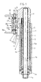
- the device shown comprises a screw 1 rotatably mounted in the bottom 2 a of a cylindrical tube 2 and having an end 1 a external to this tube for its operation in rotation.
- This screw cooperates with a nut 3 formed in the bottom of a second tubular sleeve 3.
- the tubular cylinder 3 is prevented from rotating relative to the sleeve 1.
- the sleeve 3 is slidably mounted in an intermediate sleeve 4 itself mounted sliding in the sheath 1.
- the means for immobilizing in rotation the three sheaths between them include keys 5 and 6 respectively disposed between the sheaths 2 and 4 and the sheaths 4 and 3.
- the free end of the sheath 3 carries a part 7 which forms a fitting for receiving a compression jaw of the spring to be treated.
- This fitting 7 comprises a lateral flat surface 8 from which a pin 9 fitted perpendicularly protrudes at its free end, distant from the face 8, a retaining head 10.
- the upper end of the outer sheath 2 carries a lateral fitting 11, having a flat surface 12 from which protrudes an axis 13, perpendicular to the face 12 and equipped, at its free end, with a retaining head 14 remote from the face 12, a value and parallel thereto.
- the head is oblong so that its greatest length is parallel to the axis of the barrel.
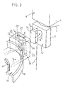
- Each of the above-mentioned fittings equipped with their head axis receives a plate 15, 16 which constitutes the support and the coupling means of a jaw 17 in the form of a flat ring portion, provided with an outer rim 18 and an inner rim 19.
- This cup which is not shown in FIG. 1, is coupled by any known means, for example welded, to a return 15 a , 16 a of the corresponding plate 15, 16, so that the annular gutter of one, defined by the flanges 18 and 19, is turned towards the annular gutter of the other.
- the coupling part of each plate 15, 16 (only the plate 16 is described with reference to FIG.
- the front front wall 21 is of a thickness E which will be at most equal to the value a of the head 14 from the surface 12. E and a correspond to sliding fit tolerances.
- the housing 20 is such that the spacing d between the two end faces is slightly greater than the thickness e of the head 10, 14 while the distance L separating the two side walls 12, 24 is greater than the width l of this head.
- the front wall 21 is notched.
- the notch 25 whose bottom is semi-cylindrical is of width equal to the diameter of the axis 9, 13.
- the axis 9,13 is housed in the notch 25 and the head 10,14 in the housing 20.
- the upper plate 15 overlaps the axis 9 from below while the lower plate 16 overlaps axis 13 from above.
- the two plates, therefore the two jaws, are identical; only their orientation is reversed.
- the distance L is greater than the width l of the head so that a movement of the plate is possible around the axis 9,13 that it overlaps, as long as the corners of the head 10,14 do not come into abutment on the sides 23 and 24 of the housing.
- the jaws can therefore tilt in contact with the turn of the spring which they trap to adopt its slope and this inclination (rotation around the overlapped axis) can vary with the pitch of the turns depending on the degree of spring compression.
- the invention allows an extremely easy installation of the device on a spring. It suffices to place the cups on the chosen turns and to retract the telescopic barrel by sliding the pins and heads in the jaw plates. The further compression of the spring, for example its disassembly, then takes place in complete safety. When it is desired to relax a spring after dismantling, it suffices to reverse the operation of the screw to extend the telescopic barrel until reaching the rest position of the spring.
Landscapes
- Engineering & Computer Science (AREA)
- Mechanical Engineering (AREA)
- Springs (AREA)
- Vehicle Cleaning, Maintenance, Repair, Refitting, And Outriggers (AREA)
Applications Claiming Priority (2)
| Application Number | Priority Date | Filing Date | Title |
|---|---|---|---|
| FR8913602 | 1989-10-18 | ||
| FR8913602A FR2653051A1 (fr) | 1989-10-18 | 1989-10-18 | Dispositif de compression de ressorts. |
Publications (1)
| Publication Number | Publication Date |
|---|---|
| EP0424247A1 true EP0424247A1 (de) | 1991-04-24 |
Family
ID=9386508
Family Applications (1)
| Application Number | Title | Priority Date | Filing Date |
|---|---|---|---|
| EP90402897A Withdrawn EP0424247A1 (de) | 1989-10-18 | 1990-10-16 | Vorrichtung zum Komprimieren von Federn |
Country Status (2)
| Country | Link |
|---|---|
| EP (1) | EP0424247A1 (de) |
| FR (1) | FR2653051A1 (de) |
Cited By (6)
| Publication number | Priority date | Publication date | Assignee | Title |
|---|---|---|---|---|
| GB2261185A (en) * | 1991-08-23 | 1993-05-12 | Sykes Pickavant Ltd | Coil spring compressor |
| EP0771616A1 (de) * | 1995-11-03 | 1997-05-07 | Sykes-Pickavant Limited | Hochbelastbarer Spiralfederkompressor |
| FR2749362A1 (fr) * | 1996-06-03 | 1997-12-05 | Mecanique Energetique | Perfectionnement aux compresseurs de ressorts |
| FR2767736A1 (fr) * | 1997-09-03 | 1999-03-05 | Virax Sa | Dispositif de pince pousse-bague utilise dans le domaine de la plomberie pour l'emboitement des tuyaux en matiere plastique ou en complexe plastique-aluminium sur des raccords |
| WO2003057414A1 (fr) * | 2002-01-11 | 2003-07-17 | Mecanique Energetique | Compresseur de ressorts de suspension de vehicule automobile |
| EP1714936A1 (de) * | 2005-04-20 | 2006-10-25 | Stork Industry Services B.V. | Hebevorrichtung zum Anbringen und/oder Entfernen von schweren Flanschschrauben und Verfahren zum Anbringen von einer solchen Flanschschraube |
Families Citing this family (1)
| Publication number | Priority date | Publication date | Assignee | Title |
|---|---|---|---|---|
| FR2876756B1 (fr) * | 2004-10-19 | 2007-01-05 | Patrick Lambert | Verin a vis |
Citations (6)
| Publication number | Priority date | Publication date | Assignee | Title |
|---|---|---|---|---|
| US3384348A (en) * | 1966-10-13 | 1968-05-21 | James A. Wicker | Spring compressing devices |
| FR2055745A1 (de) * | 1969-08-07 | 1971-04-30 | Lebre Charles | |
| DE3021084A1 (de) * | 1980-06-04 | 1981-12-24 | August Bilstein GmbH & Co KG, 5828 Ennepetal | Federspanngeraet |
| DE3208510A1 (de) * | 1981-03-10 | 1982-10-28 | Kenneth D. 43537 Maumee Ohio Kloster | Federspannwerkzeug |
| DE3335979C1 (de) * | 1983-10-04 | 1985-03-14 | Horst 7730 Villingen-Schwenningen Klann | Druckfedernspanner,insbesondere fuer Achsfedern von Kraftfahrzeugen |
| EP0250638A1 (de) * | 1986-07-04 | 1988-01-07 | Horst Klann | Druckfedernspanner |
-
1989
- 1989-10-18 FR FR8913602A patent/FR2653051A1/fr active Granted
-
1990
- 1990-10-16 EP EP90402897A patent/EP0424247A1/de not_active Withdrawn
Patent Citations (6)
| Publication number | Priority date | Publication date | Assignee | Title |
|---|---|---|---|---|
| US3384348A (en) * | 1966-10-13 | 1968-05-21 | James A. Wicker | Spring compressing devices |
| FR2055745A1 (de) * | 1969-08-07 | 1971-04-30 | Lebre Charles | |
| DE3021084A1 (de) * | 1980-06-04 | 1981-12-24 | August Bilstein GmbH & Co KG, 5828 Ennepetal | Federspanngeraet |
| DE3208510A1 (de) * | 1981-03-10 | 1982-10-28 | Kenneth D. 43537 Maumee Ohio Kloster | Federspannwerkzeug |
| DE3335979C1 (de) * | 1983-10-04 | 1985-03-14 | Horst 7730 Villingen-Schwenningen Klann | Druckfedernspanner,insbesondere fuer Achsfedern von Kraftfahrzeugen |
| EP0250638A1 (de) * | 1986-07-04 | 1988-01-07 | Horst Klann | Druckfedernspanner |
Cited By (11)
| Publication number | Priority date | Publication date | Assignee | Title |
|---|---|---|---|---|
| GB2261185A (en) * | 1991-08-23 | 1993-05-12 | Sykes Pickavant Ltd | Coil spring compressor |
| EP0771616A1 (de) * | 1995-11-03 | 1997-05-07 | Sykes-Pickavant Limited | Hochbelastbarer Spiralfederkompressor |
| FR2749362A1 (fr) * | 1996-06-03 | 1997-12-05 | Mecanique Energetique | Perfectionnement aux compresseurs de ressorts |
| EP0811547A1 (de) * | 1996-06-03 | 1997-12-10 | Mecanique Energetique | Verbesserung an Federspannern |
| FR2767736A1 (fr) * | 1997-09-03 | 1999-03-05 | Virax Sa | Dispositif de pince pousse-bague utilise dans le domaine de la plomberie pour l'emboitement des tuyaux en matiere plastique ou en complexe plastique-aluminium sur des raccords |
| EP0900633A1 (de) * | 1997-09-03 | 1999-03-10 | Virax S.A. | Zange zum Aufschieben von Ringen |
| WO2003057414A1 (fr) * | 2002-01-11 | 2003-07-17 | Mecanique Energetique | Compresseur de ressorts de suspension de vehicule automobile |
| FR2834660A1 (fr) * | 2002-01-11 | 2003-07-18 | Mecanique Energetique | Compresseur de ressorts de suspension de vehicule automobile |
| US7114228B2 (en) | 2002-01-11 | 2006-10-03 | Mecanique Energetique | Motor vehicle suspension spring compressor |
| EP1714936A1 (de) * | 2005-04-20 | 2006-10-25 | Stork Industry Services B.V. | Hebevorrichtung zum Anbringen und/oder Entfernen von schweren Flanschschrauben und Verfahren zum Anbringen von einer solchen Flanschschraube |
| NL1028828C2 (nl) * | 2005-04-20 | 2006-10-30 | Stork Industry Services B V | Hefinrichting voor gebruik bij het monteren en/of demonteren van zware flensbouten en werkwijze voor het monteren van een dergelijke flensbout. |
Also Published As
| Publication number | Publication date |
|---|---|
| FR2653051B1 (de) | 1994-08-19 |
| FR2653051A1 (fr) | 1991-04-19 |
Similar Documents
| Publication | Publication Date | Title |
|---|---|---|
| EP0322265B1 (de) | Kupplungssteuereinrichtung, insbesondere für Kraftfahrzeuge | |
| EP0417265B1 (de) | Tragbares datenverarbeitungsgerät mit einem schwenkbaren bildschirm | |
| FR2808483A1 (fr) | Dispositif de reglage motorise pour siege de vehicule | |
| EP0424247A1 (de) | Vorrichtung zum Komprimieren von Federn | |
| EP0586297A1 (de) | Vorrichtung zum axialen Ausrichten und zur Stosspositionierung von zwei länglichen Körpern | |
| EP0536005A1 (de) | Vorrichtung zum schnellen Montieren und Demontieren von zwei aufeinanderliegenden Teilen | |
| EP0398815B1 (de) | Vorrichtung zum Ein- und Ausbauen von Spiralfedern | |
| EP0114543B1 (de) | Allseitige Orientierungsvorrichtung für eine Antenne | |
| EP0491603B1 (de) | Verbindungsglied zwischen einem Scheibenwischerarm, insbesondere für Kraftfahrzeug | |
| EP0368700A1 (de) | Vorrichtung zum axialen Sperren eines teleskopischen Teiles, z.B. einer Kraftfahrzeuglenksäule | |
| EP0905410B1 (de) | Elastisches Dämpfungsglied, insbesondere für Zweimassenschwungräder und ein mit diesem ausgerüstetes Zweimassenschwungrad | |
| EP0484215B1 (de) | Druckfedernspanner | |
| FR2720151A1 (fr) | Ensemble pour la fixation amovible du berceau à la culasse d'une arme. | |
| FR2594086A1 (fr) | Dispositif de reglage perfectionne de la position angulaire d'un organe sur un arbre, notamment d'un volant sur un arbre de direction | |
| FR2486885A2 (fr) | Dispositif de commande d'un miroir de retroviseur pour vehicule | |
| FR2775946A1 (fr) | Dispositif d'accouplement d'un mecanisme de direction | |
| EP0292371A1 (de) | Radsatz für lenkbare Räder eines Kraftfahrzeuges mit teleskopischen Federbeinen mit Schrägfedern | |
| FR2540585A1 (fr) | Butee de debrayage en deux parties | |
| FR2811699A1 (fr) | Charniere a couple controle | |
| EP0505282B1 (de) | Federkompressor, insbesondere für bogenförmige Federn | |
| CA1254757A (fr) | Dispositif d'accouplement a denture pour arbres oscillants | |
| EP0744588B1 (de) | Vorrichtung zur Herstellung einer abnehmbaren Verbindung zwischen einem Verschluss und einer Wiege eines Geschützes | |
| FR2715982A1 (fr) | Tendeur de courroie pour moteur à combustion interne de véhicule automobile. | |
| FR2749362A1 (fr) | Perfectionnement aux compresseurs de ressorts | |
| FR2650232A1 (fr) | Projecteur pour vehicule avec regulation motorisee de l'orientation |
Legal Events
| Date | Code | Title | Description |
|---|---|---|---|
| PUAI | Public reference made under article 153(3) epc to a published international application that has entered the european phase |
Free format text: ORIGINAL CODE: 0009012 |
|
| 17P | Request for examination filed |
Effective date: 19901018 |
|
| AK | Designated contracting states |
Kind code of ref document: A1 Designated state(s): AT BE CH DE DK ES GB GR IT LI LU NL SE |
|
| 17Q | First examination report despatched |
Effective date: 19930111 |
|
| STAA | Information on the status of an ep patent application or granted ep patent |
Free format text: STATUS: THE APPLICATION IS DEEMED TO BE WITHDRAWN |
|
| 18D | Application deemed to be withdrawn |
Effective date: 19950314 |