EP0423904A1 - Verbesserte Anodenzusammenstellung für die selektive Galvanisierung - Google Patents
Verbesserte Anodenzusammenstellung für die selektive Galvanisierung Download PDFInfo
- Publication number
- EP0423904A1 EP0423904A1 EP90202904A EP90202904A EP0423904A1 EP 0423904 A1 EP0423904 A1 EP 0423904A1 EP 90202904 A EP90202904 A EP 90202904A EP 90202904 A EP90202904 A EP 90202904A EP 0423904 A1 EP0423904 A1 EP 0423904A1
- Authority
- EP
- European Patent Office
- Prior art keywords
- anode
- terminal
- shroud
- plating
- passageway
- Prior art date
- Legal status (The legal status is an assumption and is not a legal conclusion. Google has not performed a legal analysis and makes no representation as to the accuracy of the status listed.)
- Granted
Links
- 238000007747 plating Methods 0.000 title claims abstract description 75
- 239000004020 conductor Substances 0.000 claims description 13
- 230000000712 assembly Effects 0.000 description 25
- 238000000429 assembly Methods 0.000 description 25
- 239000003792 electrolyte Substances 0.000 description 15
- 239000000243 solution Substances 0.000 description 11
- 230000006641 stabilisation Effects 0.000 description 11
- 238000011105 stabilization Methods 0.000 description 11
- 239000000463 material Substances 0.000 description 10
- 229910052751 metal Inorganic materials 0.000 description 7
- 239000002184 metal Substances 0.000 description 7
- 238000003780 insertion Methods 0.000 description 4
- 230000037431 insertion Effects 0.000 description 4
- 238000004519 manufacturing process Methods 0.000 description 4
- 230000007246 mechanism Effects 0.000 description 4
- 150000002739 metals Chemical class 0.000 description 4
- 239000010935 stainless steel Substances 0.000 description 4
- 229910001220 stainless steel Inorganic materials 0.000 description 4
- 125000000218 acetic acid group Chemical group C(C)(=O)* 0.000 description 3
- 239000002253 acid Substances 0.000 description 3
- 239000003989 dielectric material Substances 0.000 description 3
- 239000008151 electrolyte solution Substances 0.000 description 3
- 238000009713 electroplating Methods 0.000 description 3
- 229910021645 metal ion Inorganic materials 0.000 description 3
- 238000000034 method Methods 0.000 description 3
- 229910000510 noble metal Inorganic materials 0.000 description 3
- BASFCYQUMIYNBI-UHFFFAOYSA-N platinum Chemical compound [Pt] BASFCYQUMIYNBI-UHFFFAOYSA-N 0.000 description 3
- 230000008569 process Effects 0.000 description 3
- 229920005989 resin Polymers 0.000 description 3
- 239000011347 resin Substances 0.000 description 3
- 230000007704 transition Effects 0.000 description 3
- 229920004943 Delrin® Polymers 0.000 description 2
- 229920001328 Polyvinylidene chloride Polymers 0.000 description 2
- 230000009471 action Effects 0.000 description 2
- 229910045601 alloy Inorganic materials 0.000 description 2
- 239000000956 alloy Substances 0.000 description 2
- 238000004891 communication Methods 0.000 description 2
- 230000008021 deposition Effects 0.000 description 2
- 238000009826 distribution Methods 0.000 description 2
- 239000012530 fluid Substances 0.000 description 2
- 229920006158 high molecular weight polymer Polymers 0.000 description 2
- 150000002500 ions Chemical class 0.000 description 2
- 238000013507 mapping Methods 0.000 description 2
- 239000007787 solid Substances 0.000 description 2
- 229920000785 ultra high molecular weight polyethylene Polymers 0.000 description 2
- 239000004734 Polyphenylene sulfide Substances 0.000 description 1
- 150000007513 acids Chemical class 0.000 description 1
- 239000010953 base metal Substances 0.000 description 1
- 230000015572 biosynthetic process Effects 0.000 description 1
- 230000008878 coupling Effects 0.000 description 1
- 238000010168 coupling process Methods 0.000 description 1
- 238000005859 coupling reaction Methods 0.000 description 1
- 238000002788 crimping Methods 0.000 description 1
- 238000013461 design Methods 0.000 description 1
- 230000000694 effects Effects 0.000 description 1
- 230000007717 exclusion Effects 0.000 description 1
- 238000002347 injection Methods 0.000 description 1
- 239000007924 injection Substances 0.000 description 1
- 230000002093 peripheral effect Effects 0.000 description 1
- 229910052697 platinum Inorganic materials 0.000 description 1
- 229920000069 polyphenylene sulfide Polymers 0.000 description 1
- 238000004886 process control Methods 0.000 description 1
- 230000000717 retained effect Effects 0.000 description 1
- 239000000126 substance Substances 0.000 description 1
Images



Classifications
-
- C—CHEMISTRY; METALLURGY
- C25—ELECTROLYTIC OR ELECTROPHORETIC PROCESSES; APPARATUS THEREFOR
- C25D—PROCESSES FOR THE ELECTROLYTIC OR ELECTROPHORETIC PRODUCTION OF COATINGS; ELECTROFORMING; APPARATUS THEREFOR
- C25D5/00—Electroplating characterised by the process; Pretreatment or after-treatment of workpieces
- C25D5/02—Electroplating of selected surface areas
-
- C—CHEMISTRY; METALLURGY
- C25—ELECTROLYTIC OR ELECTROPHORETIC PROCESSES; APPARATUS THEREFOR
- C25D—PROCESSES FOR THE ELECTROLYTIC OR ELECTROPHORETIC PRODUCTION OF COATINGS; ELECTROFORMING; APPARATUS THEREFOR
- C25D5/00—Electroplating characterised by the process; Pretreatment or after-treatment of workpieces
- C25D5/02—Electroplating of selected surface areas
- C25D5/026—Electroplating of selected surface areas using locally applied jets of electrolyte
Definitions
- the present invention relates to selective electroplating of electrical terminals, i.e., electroplating only the electrical contact surfaces of the terminals to the exclusion of other surfaces of the terminals and, in particular, to selectively plating terminals that are attached to a carrier strip.
- the terminals are stamped and formed from metal strip and are attached to a carrier strip.
- This carrier strip is useful for strip feeding the terminals through successive manufacturing operations.
- One necessary manufacturing operation involves plating, i.e., electroplating the electrical contact surfaces of the noble metal alloys.
- These metals are characterized by good electrical conductivity and little or no formation of oxides that reduce the conductivity. Therefore, these metals, when applied as plating, will enhance conductivity of the terminals.
- the high cost of these metals has necessitated precision deposition on the contact surfaces of the terminals, and not on surfaces of the terminals on which plating is unnecessary.
- Apparatus for plating is called a plating cell and includes an electrical anode, an electrical cathode comprised of the strip-fed terminals, and a plating solution, i.e., an electrolyte of metal ions.
- a strip feeding means feeds the strip to a strip guide.
- the strip guide guides the terminals through a plating zone while the terminals are being plated.
- the plating solution is fluidic and is placed in contact with the anode and the terminals.
- the apparatus operates by passing electrical current from the anode through the plating solution to the terminals, which comprise the cathode of the plating cell.
- the metal ions deposit as metal plating on those terminal surfaces in contact with the plating solution.
- the apparatii disclosed in the three referenced patents are designed to be used with stamped and formed terminals, wherein the contact zone is located inside the formed terminal.
- Each apparatus is comprised of an assembly of conductive and dielectric parts, all mounted for rotation on a stationary axis.
- Each of the apparatii consists generally of a mandrel that is continuously rotated as strip-fed electrical terminals are continuously fed to the mandrel, partially wrapped against it, and exited from it.
- the mandrel is turreted with a plurality of nozzles distributed about its axis of rotation.
- Anodes are associated with the nozzles and are mounted for movement into and out of the interiors of the terminals that are against the mandrel.
- a conduit supplies plating solution under pressure through the nozzles and upon the anodes.
- the nozzles inject plating solution into the interiors of the terminals in which the anodes are received.
- a source of electrical potential supplies an electrical current flow from the anodes, through the plating solution and into the interiors of the terminals in which the anodes are received.
- each mandrel has a plurality of plating cells distributed about its axis of rotation.
- Anode members or anode extensions are mounted within the assembly such that they can be moved into and out of the contact zone inside a formed terminal.
- the conductive anode members are either continually in mechanical engagement and electrical contact with or brought into electrical contact with an electrically charged member just prior to moving the anode member inside the terminal to selectively plate the contact zone.
- the anode members are held against the charged member under tension by using either a spring in the anode extension member itself or by spring loading the anode extension members against a conductive plate of the apparatus or both.
- the anode members are then moved into and out of aligned terminal members by hydraulic, mechanical, or a combination of means.
- the anode member of the anode extension be concentrically aligned within the contact zone of the terminal. If the anode is not aligned concentrically in the terminal, an uneven layer of plating material is deposited. Furthermore, for plating to occur, it is essential that the conductive anode member not come into physical contact with the terminal, which is the cathode. Should the anode touch the terminal, a short circuit results and no plating will occur in that cell.
- the present invention described below is directed to an improved selective plating apparatus which has means for assuring an essentially uniform current to each of the cells of a plating apparatus.
- the invention is designed to be used with anode assemblies of the type described below. It is to be understood that other types of anode assemblies may also be used.
- EP-A-88900318.2 from which the present application has been divided an apparatus for plating interior surfaces of electrical terminals that are spaced apart and attached to a carrier strip, that is utilized to strip-feed the terminals, comprising a rotating member mounted on a stationary conductive shaft as strip-fed terminals are continuously fed to the member, wrapped against the member and exited therefrom, the member including a plurality of nozzles distributed about its axis of rotation; a plurality of anode assembly members mounted within said nozzles, said anode members being movable into and out of the interiors of the terminals that are against the member; a conduit supplying plating solution under pressure through said nozzles and upon said anode members; a source of electrical potential for supplying electrical current flow from said anode members, through said plating solution and into the interiors of said terminals, thus forming a plurality of plating cells about said member; the apparatus being characterized in that the rotating member is dielectric and comprises a first portion
- the apparatus also includes means for providing an essentially uniform current to each of the plating cells.
- the means comprises a conductor member having one end electrically engaged and mechanically secured to a conductive portion of each anode assembly member, conductive means secured circumferentially around a forward portion of the dielectric rotating first mandrel portion proximate the conductive second mandrel portion.
- the conductive means includes a plurality of conductor member terminating apertures in which are disposed the other end of the conductor members that are attached to the anode assemblies.
- Spring tab means are also included for electrically coupling the conductive second mandrel portion with the conductive means on the first mandrel portion such that the conductive means on the first mandrel portion may rotate while remaining in electrical engagement with the stationary conductive second mandrel portion.
- the present invention is directed to an anode assembly for plating contact areas within socket terminals being plated in the previously described apparatus.
- Means for ensuring an electrical connection between the anode assembly and an electrically charged member of the apparatus may include a conductive projection extending radially outwardly from a rear section of the body member, the projection having an aperture therethrough for receiving and electrically engaging one end of a conductor member; and a conductor member having one end disposed in the aperture and the other end attachable to an electrically chargeable member of the apparatus.
- the preferred embodiment of the anode assembly also includes a second projection in the rear body section, the second projection extending radially outwardly and in an opposite direction from the first projection.
- the second projection cooperates with a camming means of the apparatus to remove the anode means from the terminal.
- the preferred embodiment of the present invention provides an anode assembly for plating contact areas within socket terminals in which the anode member is concentrically disposed within the socket terminal, an anode assembly with means for aligning a contact terminal for engagement with the anode of the assembly, means for protecting an anode member from misalignment in the terminal, a replaceable protection guide for the anode, means for ensuring electrical interconnection of the anode assembly with a current conducting member of a plating apparatus, a cost effective means of maintaining the anode assemblies, means to assure positive retraction of the anode from the terminal, and an anode that does not contain a spring member.
- FIGS 1 and 3 illustrate details of plating apparatus 10.
- Apparatus 10 is comprised of two portions, a dielectric portion 11 and a conductive portion 119.
- the dielectric portion 11 is mounted for rotation on stationary conductive shaft 52 and comprises flange 12, the stock drive index plate 22, the nozzle and socket index plate 40, the cylinder manifold 68, and socket index and cylinder manifold bearings 36 and 62 respectively.
- Conductive portion 119 is mounted in stationary position on stationary conductive shaft 52 and is comprised of cam base 120 and cam plate cover 132 and collar member 152.
- conductive wire collar 102 and conductive wire collar cover 110 are mounted circumferentially around cylinder manifold 68 and rotate with dielectric portion 11. The wire collar 102 and wire collar cover 110 provide a means for assuring electrical engagement for all the anodes of assemblies 80, apparatus 10 as will be explained in greater detail.
- Shaft 52 is profiled to cooperate with the internal apertures of bearings 36, 62 and nozzle and socket index plate 40 such that the dielectric parts are interlocked around shaft 52 and are held in place by a plurality of bolts 20.
- the conductive parts are held on the forward shaft 52 by a washer and nut 160, 162 as best seen in Figure 3.
- terminal strip 170 is comprised of a plurality of terminals 172 integral with and serially spaced along carrier strip 180. Strip 170 is fed to the apparatus 10, partially wrapped against the apparatus 10 and fed from the apparatus 10. Strip 170 is held on the apparatus 10 by means of tension belt 184 which passes through a series of pulleys 186. Tension belt 184 holds the wrapped portion of strip 170 against the surface of the apparatus during the plating process.
- terminal strip 170 is comprised of a plurality of socket terminals 172 as shown in Figure 9.
- Terminals 172 which are attached to carrier strip 180, are comprised of a socket portion 176 having a passageway therein with a contact zone 178.
- the selectively plated layer is generally a noble metal or a noble metal alloy or a plurality of layers of such metals.
- a deposit of metal plated in accordance with the invention has observable characteristics that distinguish it from characteristics of plating by other means known in the art. By using the apparatus 10, it is possible to deposit plating thicknesses of 375 x 10 ⁇ 4mm (15 microinches) and greater directly to the interior contact zone of the terminals as described in the prior art patents.
- the dielectric parts 12, 22, 40 and 62 are advantageously machined from polyvinyldichloride (PVDC), polyphenylene sulfide, or the like.
- Bearings 36 and 68 are preferably made from high molecular weight polymers such as 1900 R UHMW from Hercules, Incorporated, and other bearing materials as known in the art.
- the dielectric materials should be thermally stable in the operation range of 54.44C to 60.00C (130 to 140) degrees Fahrenheit, be machinable, and be resistant to both alkaline and acid solutions generally in the pH range from 3 to 12.
- dielectric parts 12, 22, 140 and 162 could be formed as individual units with their respective portions of bearings 36 and 68.
- most materials suitable for bearings are not sufficiently thermally stable to be usable as the dielectric parts and, conversely, materials that are sufficiently thermally stable and machinable do not perform well when used as bearings.
- the conductive parts 52, 102, 110, 120, 132 and 152 are preferably made of stainless steel.
- the dielectric and conductive parts are assembled with bolts 20, 123 and 148 as will be described more fully below.
- Insulative flange 12 has aperture 14 therein for mounting flange 12 onto shaft 52, and a plurality of apertures 16 therein for receiving bolts 20 when the apparatus 10 is assembled. Flange 12 further has apertures 15 therein for engagement with driving means (not shown) and aperture 18 for receipt of an alignment pin 79 as described hereinafter.
- Insulative stock drive index plate 22 has aperture 24 therein for mounting to stock index bearing 36 and a plurality of V-shaped notches 26 in circumferential surface 28 of the ring.
- Stock drive index plate 22 further has apertures 30 for receiving bolts 20 and aperture 31 for receiving alignment pin 79 when apparatus 10 is assembled.
- Stock index bearing 36 has aperture 38 therein for mounting to shaft 52. Stock bearing 36 is profiled to engage stock drive index plate 22.
- Insulated nozzle and socket index plate 40 has aperture 42 therein for mounting to shaft 52, a plurality of apertures 44 for receiving bolts 20 and aperture 45 for receiving alignment pin 79 when assembling the apparatus.
- Nozzle and socket index plate 40 further has a plurality of socket notches 46 on the circumferential surface 48 and a plurality of electrolyte passageways 131 on a face thereof as best seen in Figure 3.
- Cylinder manifold 68 has aperture 70 therein for mounting to a cylinder manifold bearing 62.
- Cylinder manifold 68 further has a plurality of apertures 72 for receiving bolts 20 when the apparatus is assembled; a plurality of anode assembly receiving apertures 76, each aperture including nozzle portion 77 at an outside end thereof and further including a stabilization slot near its inner end 78 as best seen in Figure 3; and alignment pin 79.
- Insulated cylinder manifold bearing 62 has aperture 64 therein for mounting bearing 62 and cylinder manifold 68 to shaft 52, the engaging surfaces being profiled to cooperate with each other and profiled shaft 52.
- Flange 12, stock drive index plate 22, nozzle and socket index plate 40, cylinder manifold 68, and shaft 52 are similar to corresponding parts in the prior art patents. Detailed descriptions will not be included herein.
- FIG. 4 shows an anode assembly 210 used in the prior art.
- the anode assembly 210 is comprised of a body member 212 and anode member 218 secured to body member 212.
- Body member 212 is comprised of a forward dielectric coated conductive member 214, a spring member 224, and a rear conductive member 226.
- Forward member 214 has reduced diameter portion 216 and conductive anode member 218 extending from a front end of portion 216.
- First member 214 further has an annular conductive collar 222 extending rearwardly therefrom.
- One end of spring member 224 is secured over collar 222.
- Rear conductive member 226 has a reduced diameter collar 228 extending forwardly therefrom which engages the other end of the spring member 224.
- Anode assembly 210 is designed to be used with electrical terminal 172 having socket or barrel portion 234 with a passageway 236 therein.
- anode member 218 When used in a plating apparatus, anode member 218 is inserted into passageway 236 of terminal member 172.
- anode member 218 In order to obtain the desired plating layer 238 inside terminal 172, it is necessary that anode member 218 be concentrically disposed within terminal 172.
- the tip 220 of anode member 218 is not protected and, therefore, is vulnerable to damage should terminal 172 not be in precise alignment with anode member 218.
- tip 220 is sufficiently out of alignment, it can touch the sides of passageway 236 and cause a short circuit.
- anode assembly 240 of the present invention is comprised of a conductive body member 242 having an anode member 256 extending forwardly from an end of member 242 and a dielectric shroud member 276 having a profiled passageway 284 therethrough for receipt of the anode means 256, and means for securing the shroud member 276 to body member 242 such that shroud member 276 extends coaxially around anode member 56.
- Body member 242 has a first reduced diameter section 244 extending forwardly therefrom and defining a stop surface 246, or reference surface between the reduced diameter section 244 and the body member 242.
- the body member 242 further has a smaller diameter anode-receiving section 248 extending forwardly from the reduced diameter section 244 and concentric therewith.
- Smaller diameter anode-receiving section 248 has a coaxial bore 254 extending therethrough from front end 252 thereof.
- Anode member 256 is secured in bore 254 of anode-receiving section 248, preferably by crimping, although other means may also be used.
- Anode member 256 is dimensioned to be received within a terminal to be plated.
- Body member 242 further has a first radial aperture 262 therein for receipt of a stabilization or location pin 264.
- Pin 264 cooperates with a location means within a plating apparatus to stabilize the position of cylindrical anode assembly 240 by preventing rotation.
- stabilization pin 264 further has aperture 266 therein for receipt of conductor wire member 268 therein.
- Body member 242 also has a second radial aperture 270 therein for receiving retraction pin 272.
- Retraction pin 272 cooperates with a camming mechanism of the plating apparatus to retract anode assembly 240 and remove anode member 256 from passageway 236 of terminal 172.
- radial apertures 262 and 270 extend through body member 242 and be dimensioned to be slightly smaller than pins 264, 272. Apertures 262 and 270 can then be remade to provide a corresponding secure interference fit with pins 264, 272 respectively.
- body member 242 is made of stainless steel and anode member 256 is platinum.
- Retraction pin 272 is preferably an extrudable, moldable or machinable dielectric material and, in particular, a dielectric material that is resistant to acids and wear, such as an acetyl resin or high molecular weight polymers.
- a dielectric material that is resistant to acids and wear, such as an acetyl resin or high molecular weight polymers.
- One suitable material is Delrin R , an acetyl resin available from E. I.
- Stabilization pin 264 may be made from the same material as pin 272 or may be made from a conductive material as will be explained below.
- Shroud member 276 is comprised of a forward terminal receiving portion 278, middle portion 280, and rearward body receiving portion 282.
- Shroud member 276 further has profiled cylindrical passageway 284 extending axially therethrough.
- Passageway 284 has a forward portion 286 in the terminal receiving portion 278, the forward portion further having a lead-in means 288 for guiding terminal 172 into position.
- Forward passageway section 286 has an inner diameter selected to be just greater than the outside diameter of the terminal to be plated.
- Forward passageway portion 286 further has inner support portion 290 having aperture 291 extending axially therethrough for receiving anode member 256 when shroud member 276 is mounted to body member 242.
- Inner support portion 290 is centrally located within passageway 284 and is positioned and secured therein to form nozzles electrolyte passageway openings 293 into forward passageway 286.
- Support portion 290 extends axially rearwardly into middle shroud portion 280, the support portion being spaced from surfaces of the profiled passageway.
- Middle portion 280 of the shroud member is reduced in diameter from forward section 278 and rearward section 282 thus forming annular recess 281.
- Middle section 280 further has electrolyte apertures 298 extending radially into the middle portion 280, electrolyte apertures 298 being in communication with nozzle openings 293 in forward portion 286.
- Nozzle apertures 298 cooperate with a corresponding electrolyte passageway in a plating apparatus and receive the electrolyte solution from the apparatus.
- Passageway 284 includes a rearward section 300 having a diameter no greater than first reduced diameter section 244 of body member 242 such that shroud 276 may be removably mounted on the reduced diameter section 244 and be secured thereto through an interference fit between reduced diameter section 242 and the rearward passageway 300.
- Passageway 300 may also include ribs 301 for increasing the interference fit between the body and shroud members.
- Profiled passageway 284 further includes a small diameter passageway 298 forward of rear passageway section 300 and dimensioned for receiving the anode receiving section 248 of body member 242 when shroud 276 is mounted to body 242.
- anode member 256 passes through aperture 291 and inner support member 90 and is held concentrically within forward passageway 286.
- forward terminal receiving portion 278 of shroud 276 extends beyond tip 258 of anode member 256, thereby protecting tip 258 and anode member 256 from being bent as anode member 256 is inserted into the terminal 172.
- Figure 8 illustrates the insertion of anode member 256 into terminal passageway 136.
- lead-in means 288 which includes tapered sides 287. Sides 287 straighten terminal 172 when it is out of alignment so that the anode member 256 can enter passageway 236 and be concentric therewith.
- the lead-in means of shroud 276 will guide terminals that are slightly out of alignment and protect the anode assembly and the plating apparatus from accidental damage.
- Positioning anode member 256 in the center of the socket terminal 172 gives better plating distribution and better process control.
- Anode assembly 240 of the present invention provides, therefore, superior results as compared with the prior art anode of Figure 4.
- stabilization pin 264 must be made from a conductive material, such as stainless steel.
- Pin 264 also includes aperture 266 which receives and is terminated to one end of a conductor member 268, preferably a length of essentially flexible stranded or solid wire.
- stock drive index plate 22 further has V-notches 26 for stock which align strip 170 of terminals 172 along a portion of the circumference of assembled apparatus 10.
- Nozzle and socket index plate 40 has a plurality of notches 46 for receiving the socket portions of terminals 172 and aligning them with corresponding anode assemblies 240 in assembled apparatus 10.
- the peripheral surfaces of the flange 12, index ring 22 and nozzle and socket index plate 40 comprise the surface 43 against which the strip 170 of terminals 172 is disposed during the plating operation as is best seen in Figure 9.
- wire collar 102 and wire collar cover 110 are mounted to the exterior surface of cylinder manifold 68 proximate its front face 69 such that apertures 106 in the wire collar 102 are aligned with anode assembly receiving apertures 76 and in particular stabilization slots 78 in cylinder manifold 68 but exterior thereto, as will be explained more fully below.
- Stationary conductive portion 119 is comprised of cam base metal plate 120 having aperture 126 therein for mounting to shaft 52 and a plurality of apertures 128 therein for receiving bolts 130 in assembling apparatus 10.
- Cam base plate 120 is preferably undercut at 121 to reduce both weight of the apparatus and friction between stationary plate 120 and rotating cylinder manifold 68.
- Cam base plate 120 is attached by bolts 130 to collar member 152.
- Cam base plate 120 also has camming surface 122 along its circumference and an annular extension on surface 123 for receiving cam plate cover 132 in the assembled unit as best seen in Figure 3.
- Cam plate cover 132 has aperture 134 for receiving cam base plate 120, a plurality of bolt apertures 135 for use in mounting cam plate cover 132 to cam base plate 120 and a camming surface 140 along its circumference which cooperates with the camming surface 122 to provide a camming track 126, as best seen in Figure 10, to move anode assemblies 240 into and out of engagement with terminal members 172.
- the camming track surfaces are disposed about the circumference of plate 120 and cover 132.
- the surface extends axially forwardly from cam base plate 120 and axially rearwardly from cam cover 132.
- anode assemblies 240 rotate in cylinder manifold 68.
- the rearward end 260 of anode assemblies 240 extend axially rearwardly from rotating section 11 and retraction pin 272 rides in camming track 126.
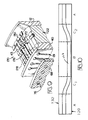
- FIG. 10 shows a mapping of camming track 126 along the circumferential surfaces of cam base plate 120 and cam cover 132.
- Track 126 is formed by attaching cam cover 132 to base plate 120 by means of bolts 138 as shown in Figure 3.
- the circumferential surface of plate 120 and cover 132 have been cut along line 10-10 of Figure 3 and opened flat. Track 126 is shown from right to left to progress from a fully retracted anode member to a fully inserted one to a fully retracted anode member.
- the sinuous surface is defined by two straight segments A, B each comprising almost half the circumference of the camming track, joined by two short angled transition surfaces C1 and C2 gently flared into the two straight segments to provide a smooth and gentle transition from one segment to the other.
- camming track 126 engages retraction pin 272 of anode assembly 240 such that its anode member is retracted from the terminal position while pin 272 travels along first section A and is fully inserted while pin 272 travels along section B.
- the anode member moves from full retraction to full insertion while pin 272 is in the two transition sections C1 and C2.
- the camming system for moving the anode assemblies into engagement with respective terminals 172 allows a greater variance of tolerances between the various pieces.
- the anode assemblies are not spring loaded but are forced to move by action of the camming track.
- the cylinder manifold 68 and cylinder manifold bearing 62 are mounted onto shaft 52 from one direction and nozzle and socket index plate 40, index bearing 36, index ring 22, and flange 12 are mounted from the other. These four main parts are secured together by a plurality of bolts 20 and held securely in place on shaft 52 by the profiled shapes of dielectric members and shaft 52. Wire collar 102 is then attached to cylinder manifold 68.
- Electrode passageways 131 in nozzle and socket plate 40 are brought into communication with manifold 56 of shaft 52 thereby permitting plating solution to be pumped through passageways 131, into electrolyte aperture 296 of anode assembly 240 into nozzle openings, over the anode member 256, and into terminal 172.
- Conductive shaft 52 has a mounting means for mounting the shaft in stationary position on support surface 182 such as a plating tank shown in Figure 2.
- cam base plate 120 is joined to the collar 152 by bolts 130 and the unit is attached to shaft 52 by washer and nuts 160, 162. Collar 152 and cam base plate 120 are retained in proper alignment by set screw 156 which is spring loaded and engaged in keying slot 58 of shaft 52.
- Anode assemblies 240 are then inserted into cylinder manifold 68 and extend over the nozzle plate such that electrolyte apertures 296 in anode assembly 240 are in alignment with electrolyte passageways 131 of the apparatus.
- retraction pins 272 of assembly 240 lie along camming track 126 as previously described and stabilization pins 264 lie in respective stabilization slots 78 of cylinder manifold 68.
- the other end of the wire conductor 268 from anode assembly 240 is then inserted into termination section 106 of the wire collar member 102 and attached with a set screw 108.
- Wire collar cover 110 is then attached to the unit to protect wire conductors 268 on anode assemblies 240 from being damaged during the plating process.
- the cam plate cover 132 is then attached to the cam base plate 120 thus encapturing the anode assemblies 240.
- one or more spring tab members 144 are attached by bolt 148 to cam plate cover 132 in assembled apparatus 10 to provide a conductive path through spring tabs 146 from cam plate cover 132 to wire collar cover 110, thus assuring electrical connection for each anode assembly and assuring that a uniform current will be present in each one of the plating cells of apparatus 10.
- FIG 11 shows an alternative embodiment of the anode assembly 340 in which the stabilization pin 364 is a solid member designed to be used without the positive electrical connection feature.
- anode assembly 340 must depend upon physical contact with a conductive assembly member for establishing electrical connection before plating can occur.
- Stabilization pin 364 may be either dielectric or conductive.
- Figure 12 shows an alternative form of the apparatus, which includes the camming mechanism as previously described but eliminates the wire collar member 102 and wire cover 10 and wire on anode assemblies.
- Anode assemblies 340 are moved into place by the action of the cam plate cover 132 and the interrelation between the cam plate cover 132 and the cam base plate 120. Electrical engagement between the end of anode assembly 340 and cam cover 132 at 260 provides electrical contact between the two surfaces.
- driving means rotates the apparatus 10 and strip 170 is fed onto the apparatus 10.
- Electrolyte solution is supplied under pressure into the conduit 56 of shaft 52.
- An electrical potential from source E (not shown) is applied between the cam base plate 120 and strip-fed terminals 172 to produce a current I.
- Terminals 172 serve as cathodes onto which noble or precious or semiprecious metal ions of the electrolyte solution are to be plated.
- each of the electrolyte passageways 131 communicates with the electrolyte manifold 58.
- the electrolyte flows from conduit 56 through passageway 131, through nozzle aperture 296 into the nozzle and over the anode members of anode assemblies 240 which lie within the interior passageway of terminal members 170.
- the electrolyte wets the terminal interior and the anode members. Sufficient ion density and current density are present for the ions to deposit as plating upon the surfaces of the interior of the terminal. The proximity of the anode members to the contact surfaces to ensure that the surfaces of the terminal interiors are plated rather than other terminal surfaces. Excess electrolyte will flow past anode members and will be returned to the plating bath.
- Means are provided for easily loading terminal strips 170 owing to cam retract rod 60 and spring 61 mounted within shaft 52.
- rod 60 When rod 60 is activated by drive means (not shown), the conductive portion containing cam assembly is moved forward on shaft 52 so that all of anode assemblies 240 are disengaged from terminal area 43. This permits terminal strip 170 to be loaded onto surface 43 without interference from anode assemblies.
- rod 60 is again activated to engage the cam assembly and anode assemblies 240 into their respective positions.
- conductive portion 119 is moved, the screw moves along keying slot 58 to maintain alignment of dielectric and conductive portions 11 and 119 respectively.
- can retract rod 60 is operated pneumatically. It is to be understood that other means may be used.
- the anode member is a platinum wire which, along with stainless steel body member 242, will last indefinitely.
- Dielectric shrouds 276, however, are subject to wear, particularly where terminals enter the shroud passageway. Each shroud 276 will last about one hundred thousand insertions before needing to be replaced.
- assembly 10 permits easy set-up and replacement of anode assemblies 80 as they wear.
- Dielectric shroud members 276 can be easily replaced when they begin to show wear. It is, therefore, more cost effective to replace shroud members 276 at regular intervals to assure that plating will be accurately deposited in terminals and that apparatus 10 will function effectively.
- Apparatus 10 has advantages over the assemblies of the prior art, in that it has fewer parts, easy access to replaceability of the anodes, and more reliable alignment of the anodes in the terminals by use of the anode assembly as shown in the preferred embodiment.
- the stabilization pins keep the cylindrical body members from rotating in position so that they will remain in alignment. It is preferable that the material for the shroud and dielectric pins be injection moldable and/or extrudable. In addition, the material should be thermally stable and acid resistant.
- One such material is Delrin R , an acetyl resin available from E. I. DuPont de Nemours and Company.
- socket terminals may be plated. Dimensional changes in the strip of terminals such as centerline spacing of the terminals, the width of strip of terminals, and location of the contact surface within the terminal can be accommodated easily by corresponding dimensional changes in the spacing and arrangement of the anode assemblies and indexing wheel. It is to be understood that the terminals, the exact shape of the anode bodies and the shroud member are merely representative of the various shapes that might be used. It is further to be understood that the front of the terminal receiving portion of the shroud member may be reshaped to accommodate other terminal shapes.
Landscapes
- Chemical & Material Sciences (AREA)
- Engineering & Computer Science (AREA)
- Chemical Kinetics & Catalysis (AREA)
- Electrochemistry (AREA)
- Materials Engineering (AREA)
- Metallurgy (AREA)
- Organic Chemistry (AREA)
- Electroplating Methods And Accessories (AREA)
Applications Claiming Priority (4)
| Application Number | Priority Date | Filing Date | Title |
|---|---|---|---|
| US946401 | 1986-12-23 | ||
| US06/946,401 US4687562A (en) | 1986-12-23 | 1986-12-23 | Anode assembly for selectively plating electrical terminals |
| US06/946,467 US4690747A (en) | 1986-12-23 | 1986-12-23 | Selective plating apparatus |
| US946467 | 1986-12-23 |
Related Parent Applications (1)
| Application Number | Title | Priority Date | Filing Date |
|---|---|---|---|
| EP88900318.2 Division | 1987-12-04 |
Publications (2)
| Publication Number | Publication Date |
|---|---|
| EP0423904A1 true EP0423904A1 (de) | 1991-04-24 |
| EP0423904B1 EP0423904B1 (de) | 1993-11-24 |
Family
ID=27130237
Family Applications (2)
| Application Number | Title | Priority Date | Filing Date |
|---|---|---|---|
| EP90202904A Expired - Lifetime EP0423904B1 (de) | 1986-12-23 | 1987-12-04 | Verbesserte Anodenzusammenstellung für die selektive Galvanisierung |
| EP88900318A Expired - Lifetime EP0294426B1 (de) | 1986-12-23 | 1987-12-04 | Verbesserte selektive galvanisier-vorrichtung und anodenzusammenstellung dafür |
Family Applications After (1)
| Application Number | Title | Priority Date | Filing Date |
|---|---|---|---|
| EP88900318A Expired - Lifetime EP0294426B1 (de) | 1986-12-23 | 1987-12-04 | Verbesserte selektive galvanisier-vorrichtung und anodenzusammenstellung dafür |
Country Status (5)
| Country | Link |
|---|---|
| EP (2) | EP0423904B1 (de) |
| JP (1) | JP2654443B2 (de) |
| KR (1) | KR950006837B1 (de) |
| DE (2) | DE3788287T2 (de) |
| WO (1) | WO1988004699A2 (de) |
Families Citing this family (1)
| Publication number | Priority date | Publication date | Assignee | Title |
|---|---|---|---|---|
| CN115976617B (zh) * | 2022-11-23 | 2024-11-29 | 西安空间无线电技术研究所 | 一种辅助阳极及铝合金多弯波导零件镀银工艺方法 |
Citations (1)
| Publication number | Priority date | Publication date | Assignee | Title |
|---|---|---|---|---|
| EP0148570A2 (de) * | 1983-12-22 | 1985-07-17 | AMP INCORPORATED (a New Jersey corporation) | Verfahren und Vorrichtung zur selektiven Plattierung von elektrischen Kontaktstücken |
-
1987
- 1987-12-04 WO PCT/US1987/003193 patent/WO1988004699A2/en not_active Ceased
- 1987-12-04 DE DE3788287T patent/DE3788287T2/de not_active Expired - Fee Related
- 1987-12-04 DE DE8888900318T patent/DE3778884D1/de not_active Expired - Fee Related
- 1987-12-04 KR KR1019880701020A patent/KR950006837B1/ko not_active Expired - Fee Related
- 1987-12-04 EP EP90202904A patent/EP0423904B1/de not_active Expired - Lifetime
- 1987-12-04 JP JP63500695A patent/JP2654443B2/ja not_active Expired - Lifetime
- 1987-12-04 EP EP88900318A patent/EP0294426B1/de not_active Expired - Lifetime
Patent Citations (1)
| Publication number | Priority date | Publication date | Assignee | Title |
|---|---|---|---|---|
| EP0148570A2 (de) * | 1983-12-22 | 1985-07-17 | AMP INCORPORATED (a New Jersey corporation) | Verfahren und Vorrichtung zur selektiven Plattierung von elektrischen Kontaktstücken |
Also Published As
| Publication number | Publication date |
|---|---|
| JPH01501637A (ja) | 1989-06-08 |
| EP0294426B1 (de) | 1992-05-06 |
| DE3788287D1 (de) | 1994-01-05 |
| JP2654443B2 (ja) | 1997-09-17 |
| EP0423904B1 (de) | 1993-11-24 |
| DE3788287T2 (de) | 1994-06-30 |
| KR950006837B1 (ko) | 1995-06-23 |
| DE3778884D1 (de) | 1992-06-11 |
| WO1988004699A2 (en) | 1988-06-30 |
| KR890700176A (ko) | 1989-03-10 |
| EP0294426A1 (de) | 1988-12-14 |
| WO1988004699A3 (en) | 1988-07-28 |
Similar Documents
| Publication | Publication Date | Title |
|---|---|---|
| US4384926A (en) | Plating interior surfaces of electrical terminals | |
| CA1175520A (en) | Electric terminals having plated interior surfaces, apparatus for and method of selectively plating said terminals | |
| US8293080B2 (en) | Contact ring having electrically conductive brush | |
| US4687562A (en) | Anode assembly for selectively plating electrical terminals | |
| US4690747A (en) | Selective plating apparatus | |
| CA2062089A1 (en) | Electrolytic cell anode | |
| EP0183769B1 (de) | Vorrichtung zum selektiven galvanisieren | |
| EP0423904B1 (de) | Verbesserte Anodenzusammenstellung für die selektive Galvanisierung | |
| HK12392A (en) | Method and apparatus for electroplating a metallic deposit on interconnected metallic components and/or metallized products | |
| EP0148570A2 (de) | Verfahren und Vorrichtung zur selektiven Plattierung von elektrischen Kontaktstücken | |
| US4904364A (en) | Anode assembly for selectively plating interior surfaces of electrical terminals | |
| US4911813A (en) | Apparatus for selectively plating interior surfaces of electrical terminals | |
| EP0059481A1 (de) | Vorrichtung zur Hochgeschwindigkeitselektroplattierung | |
| EP0335909B1 (de) | Vorrichtung zum selektiven elektrolytischen plattieren von kontaktstiften | |
| DeWitt et al. | Apparatus for electrodepositing metal | |
| JPS6039192A (ja) | 噴射メッキ用のノズル装置 |
Legal Events
| Date | Code | Title | Description |
|---|---|---|---|
| PUAI | Public reference made under article 153(3) epc to a published international application that has entered the european phase |
Free format text: ORIGINAL CODE: 0009012 |
|
| 17P | Request for examination filed |
Effective date: 19901227 |
|
| AC | Divisional application: reference to earlier application |
Ref document number: 294426 Country of ref document: EP |
|
| AK | Designated contracting states |
Kind code of ref document: A1 Designated state(s): DE FR GB IT NL |
|
| RAP1 | Party data changed (applicant data changed or rights of an application transferred) |
Owner name: THE WHITAKER CORPORATION |
|
| 17Q | First examination report despatched |
Effective date: 19930209 |
|
| GRAA | (expected) grant |
Free format text: ORIGINAL CODE: 0009210 |
|
| ITF | It: translation for a ep patent filed | ||
| AC | Divisional application: reference to earlier application |
Ref document number: 294426 Country of ref document: EP |
|
| AK | Designated contracting states |
Kind code of ref document: B1 Designated state(s): DE FR GB IT NL |
|
| REF | Corresponds to: |
Ref document number: 3788287 Country of ref document: DE Date of ref document: 19940105 |
|
| ET | Fr: translation filed | ||
| PLBE | No opposition filed within time limit |
Free format text: ORIGINAL CODE: 0009261 |
|
| STAA | Information on the status of an ep patent application or granted ep patent |
Free format text: STATUS: NO OPPOSITION FILED WITHIN TIME LIMIT |
|
| 26N | No opposition filed | ||
| PGFP | Annual fee paid to national office [announced via postgrant information from national office to epo] |
Ref country code: GB Payment date: 19961108 Year of fee payment: 10 |
|
| PGFP | Annual fee paid to national office [announced via postgrant information from national office to epo] |
Ref country code: FR Payment date: 19961211 Year of fee payment: 10 |
|
| PGFP | Annual fee paid to national office [announced via postgrant information from national office to epo] |
Ref country code: DE Payment date: 19961227 Year of fee payment: 10 |
|
| PG25 | Lapsed in a contracting state [announced via postgrant information from national office to epo] |
Ref country code: GB Free format text: LAPSE BECAUSE OF NON-PAYMENT OF DUE FEES Effective date: 19971204 |
|
| PG25 | Lapsed in a contracting state [announced via postgrant information from national office to epo] |
Ref country code: FR Free format text: THE PATENT HAS BEEN ANNULLED BY A DECISION OF A NATIONAL AUTHORITY Effective date: 19971231 |
|
| GBPC | Gb: european patent ceased through non-payment of renewal fee |
Effective date: 19971204 |
|
| PG25 | Lapsed in a contracting state [announced via postgrant information from national office to epo] |
Ref country code: DE Free format text: LAPSE BECAUSE OF NON-PAYMENT OF DUE FEES Effective date: 19980901 |
|
| PGFP | Annual fee paid to national office [announced via postgrant information from national office to epo] |
Ref country code: NL Payment date: 19980914 Year of fee payment: 12 |
|
| REG | Reference to a national code |
Ref country code: FR Ref legal event code: ST |
|
| PG25 | Lapsed in a contracting state [announced via postgrant information from national office to epo] |
Ref country code: NL Free format text: LAPSE BECAUSE OF NON-PAYMENT OF DUE FEES Effective date: 20000701 |
|
| NLV4 | Nl: lapsed or anulled due to non-payment of the annual fee |
Effective date: 20000701 |
|
| PG25 | Lapsed in a contracting state [announced via postgrant information from national office to epo] |
Ref country code: IT Free format text: LAPSE BECAUSE OF NON-PAYMENT OF DUE FEES;WARNING: LAPSES OF ITALIAN PATENTS WITH EFFECTIVE DATE BEFORE 2007 MAY HAVE OCCURRED AT ANY TIME BEFORE 2007. THE CORRECT EFFECTIVE DATE MAY BE DIFFERENT FROM THE ONE RECORDED. Effective date: 20051204 |