EP0423811B1 - Sheet transport unit for recording systems - Google Patents
Sheet transport unit for recording systems Download PDFInfo
- Publication number
- EP0423811B1 EP0423811B1 EP90120089A EP90120089A EP0423811B1 EP 0423811 B1 EP0423811 B1 EP 0423811B1 EP 90120089 A EP90120089 A EP 90120089A EP 90120089 A EP90120089 A EP 90120089A EP 0423811 B1 EP0423811 B1 EP 0423811B1
- Authority
- EP
- European Patent Office
- Prior art keywords
- pulse motor
- recording
- sheet
- sheet transport
- drive
- Prior art date
- Legal status (The legal status is an assumption and is not a legal conclusion. Google has not performed a legal analysis and makes no representation as to the accuracy of the status listed.)
- Expired - Lifetime
Links
Images


Classifications
-
- B—PERFORMING OPERATIONS; TRANSPORTING
- B41—PRINTING; LINING MACHINES; TYPEWRITERS; STAMPS
- B41J—TYPEWRITERS; SELECTIVE PRINTING MECHANISMS, i.e. MECHANISMS PRINTING OTHERWISE THAN FROM A FORME; CORRECTION OF TYPOGRAPHICAL ERRORS
- B41J13/00—Devices or arrangements of selective printing mechanisms, e.g. ink-jet printers or thermal printers, specially adapted for supporting or handling copy material in short lengths, e.g. sheets
- B41J13/0009—Devices or arrangements of selective printing mechanisms, e.g. ink-jet printers or thermal printers, specially adapted for supporting or handling copy material in short lengths, e.g. sheets control of the transport of the copy material
- B41J13/0018—Devices or arrangements of selective printing mechanisms, e.g. ink-jet printers or thermal printers, specially adapted for supporting or handling copy material in short lengths, e.g. sheets control of the transport of the copy material in the sheet input section of automatic paper handling systems
-
- B—PERFORMING OPERATIONS; TRANSPORTING
- B41—PRINTING; LINING MACHINES; TYPEWRITERS; STAMPS
- B41J—TYPEWRITERS; SELECTIVE PRINTING MECHANISMS, i.e. MECHANISMS PRINTING OTHERWISE THAN FROM A FORME; CORRECTION OF TYPOGRAPHICAL ERRORS
- B41J2/00—Typewriters or selective printing mechanisms characterised by the printing or marking process for which they are designed
- B41J2/005—Typewriters or selective printing mechanisms characterised by the printing or marking process for which they are designed characterised by bringing liquid or particles selectively into contact with a printing material
- B41J2/01—Ink jet
- B41J2/135—Nozzles
- B41J2/165—Preventing or detecting of nozzle clogging, e.g. cleaning, capping or moistening for nozzles
- B41J2/16505—Caps, spittoons or covers for cleaning or preventing drying out
- B41J2/16508—Caps, spittoons or covers for cleaning or preventing drying out connected with the printer frame
-
- B—PERFORMING OPERATIONS; TRANSPORTING
- B41—PRINTING; LINING MACHINES; TYPEWRITERS; STAMPS
- B41J—TYPEWRITERS; SELECTIVE PRINTING MECHANISMS, i.e. MECHANISMS PRINTING OTHERWISE THAN FROM A FORME; CORRECTION OF TYPOGRAPHICAL ERRORS
- B41J2/00—Typewriters or selective printing mechanisms characterised by the printing or marking process for which they are designed
- B41J2/005—Typewriters or selective printing mechanisms characterised by the printing or marking process for which they are designed characterised by bringing liquid or particles selectively into contact with a printing material
- B41J2/01—Ink jet
- B41J2/135—Nozzles
- B41J2/165—Preventing or detecting of nozzle clogging, e.g. cleaning, capping or moistening for nozzles
- B41J2/16517—Cleaning of print head nozzles
- B41J2/1652—Cleaning of print head nozzles by driving a fluid through the nozzles to the outside thereof, e.g. by applying pressure to the inside or vacuum at the outside of the print head
- B41J2/16532—Cleaning of print head nozzles by driving a fluid through the nozzles to the outside thereof, e.g. by applying pressure to the inside or vacuum at the outside of the print head by applying vacuum only
-
- Y—GENERAL TAGGING OF NEW TECHNOLOGICAL DEVELOPMENTS; GENERAL TAGGING OF CROSS-SECTIONAL TECHNOLOGIES SPANNING OVER SEVERAL SECTIONS OF THE IPC; TECHNICAL SUBJECTS COVERED BY FORMER USPC CROSS-REFERENCE ART COLLECTIONS [XRACs] AND DIGESTS
- Y10—TECHNICAL SUBJECTS COVERED BY FORMER USPC
- Y10S—TECHNICAL SUBJECTS COVERED BY FORMER USPC CROSS-REFERENCE ART COLLECTIONS [XRACs] AND DIGESTS
- Y10S400/00—Typewriting machines
- Y10S400/902—Stepping-motor drive for web feed
Definitions
- This invention relates to a recording system which feeds a recording sheet intermittently by a given pitch using a pulse motor to thereby form images on it, more particularly to a pulse motor driving system used as a driving source for the recording sheet transport mechanism in the recording system.
- the recording system for a printer, facsimile, or copying machine has such a configuration that the energy generating unit for imaging elements of a recording head is driven based on recording data to record images on paper, plastic sheets, or any other recording medium.
- This type of recording system is usually of a line print type to record one whole line, a page print type to record one whole page, or of a serial type to record data while moving the carriage equipped with a recording head over a recording sheet, which then feeds the recording sheet by a given pitch when recording of one line completes to be ready for recording of the next line.
- a pulse motor ensuring excellent positioning accuracy is generally employed as a driving source to transport (feed) recording sheets.
- a member related to the sheet feed accuracy such as; a driving transfer means for sheet transport units or a feed roller which directly touches recording sheets to transport them, must permit high accuracy.
- the pulse motor for sheet feed is often used not only to feed sheets but also to drive any load including a suction recovery pump located at the exit of an ink jet recording system.
- the mechanism having a load variation should be driven by another driving source.
- a clutch is interposed between the sheet transport mechanism and the mechanism whose load varies.
- a pulse motor is energized in its stop period during intermittent sheet feet in order to retain a holding torque, whereby the pulse motor is used as a dedicated sheet feed pulse motor for recording systems (JP-A-54-49026).
- the US-A-4 769 585 also discloses such a recording system, comprising sheet transport means for feeding a recording sheet quantitatively and intermittently, a pulse motor for driving said sheet transport means, and drive control means for controlling the drive of said pulse motor.
- a first holding torque is generated by feeding a predetermined current to the pulse motor during the whole stop period within the line feed operation.
- the holding torque is reduced to a second holding torque less than the first holding torque to thereby permit the operator to feed the printing medium manually.
- multiple different current apply intervals can be specified within the stop period during intermittend sheet feed, and the drive current can be decreased gradually according to the degree of load variation. Since, thereby, the drive current is disconnected after the drive stops, the generation of excessive heat can be prevented.
- Figure 1 shows a schematic longitudinal cross section demonstrating major sections of a recording system equipped with a sheet transport unit in which this invention is adopted.
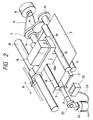
- Figure 2 shows a schematic oblique view demonstrating the major sections of the recording system in Figure 1.
- Figure 3 is a pulse motor rotation control circuit diagram for the recording system shown in Figure 1.
- Figure 4 is graphs indicating the pulse motor control signals and the current waveforms of phrases.
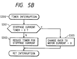
- FIGS. 5A and 5B are flowcharts representing operations of a sheet transport unit in which this invention is adopted.
- Figure 1 shows a sheet transport system for recording systems.
- Figure 2 shows a perspective view of the sheet transport system in Figure 1.
- the sheet feed roller 3 halts at the illustrated position after a single rotation. Then, transporting force for the recording sheet 2 quenches. At this time, the tip of the recording sheet 2 is sandwiched between a lower transport roller 9 a pulse motor 8 drives and an upper transport roller 10 which rotates accordingly when pressed toward the lower transport roller. Thereafter, the recording sheet 2 is restricted in its feed pitch by a pair of these rollers 9 and 10.
- the lower transport roller 9 is driven by the pulse motor 8 via a belt 6 and a pulley 7.
- the recording sheet 2 is further fed to stop when its tip is caught between a lower sheet discharge roller 11 and an upper sheet discharge roller 12.
- the upper sheet discharge roller 12 is held down to the lower sheet discharge roller 11 by means of a spring unshown.
- the lower sheet discharge roller 11 is coupled with the lower transport roller 9 via gears 14, 15, and 16, so that the lower sheet discharge roller 11 will rotate faster by a given percentage (for example, 2 %).
- the recording sheet 2 always remains properly tensioned owing to a platen 17.
- a carriage 19 having a recording head 18 scans along a rail 20 in arrow B direction, whereby recording for a single line is performed.
- the recording sheet 2 is discharged onto a sheet discharge tray 21 by a pair of sheet discharge rollers 11 and 12.
- an ink exit of the recording head 18 may clog and fail to supply ink for some portions.
- This clogging can be recovered (cleared) by a suction recovery mechanism.
- an exit surface 18A of the recording head 18 is sealed with a cap 22.
- a pump 24 is used to suck inside of the cap 22 via a tube 23.
- clogging of each exit is cleared (recovered). This is the suction recovery mechanism.
- the suction pump 24 is driven when pushed by a cam 25 fixed at the end of the lower transport roller 9.
- a pulse motor 8 is used to place a recording sheet 2 in a sheet transport unit of recording systems which feeds sheets quantitatively and intermittently.
- Multiple different current apply intervals are specified within the stop duration during intermittent sheet feed, so that a maximum amount of current will be applied to the same phase as that in which the motor drive stops during the first interval immediately after the motor drive stops.
- a pulse motor 8 stops during intermittent and quantitative feed of a recording sheet 2 or when the pulse motor stops after the recording sheet 2 is fed by a given pitch at a time of line feed, a given amount of current is applied to the same phase as that in which the motor drive stops during a given period of time immediately after the drive stops. This helps increase in a holding torque. Thereby, the pulse motor 8 always stops rotating at the same position.
- Figure 3 shows a circuit to control rotation of the above pulse motor 8.
- 26 represents a microcomputer to control rotation or stoppage, rotation rate, rotation speed, and driving current for the pulse motor 8.
- the microcomputer 26 incorporates a timer T and outputs control signals to a pulse motor driving IC 27 as well as driving current control elements (Tr1 and Tr2) 33 and 34.
- the pulse motor driving IC 27 detects currents flowing phases A, A , B, and B of the pulse motor 8 using voltages across current detecting resistors (R SA and R SB ) 28 and 29. Then, the currents are flown until the voltages become equal to comparison voltage V REF generated through voltage dividing resistors (R1 and R2) 30 and 31. Thus, chopping is done to control constant current.
- the SLA7024M of Sanken Electric Co., Ltd. may be used as the pulse motor driving IC 27.
- the comparison voltage V REF varies with on's or off's of driving current control elements (Tr1 and Tr2) 33 and 34 according to the following expressions: When both Tr1 and Tr2 are off; When Tr1 is on and Tr2 is off; When Tr1 is off and Tr2 is on; (3) V REF ⁇ 0 Under the control of the comparison voltages given by the above expression (1), (2), and (3), the driving currents (1), (2), and (3) get smaller in that order. That current values are changeable.
- Figure 4 shows the waveforms of signals INA, IN A , INB, and IN B sent from the microcomputer 26 to the pulse motor driving IC 27.
- the current waveforms flowing the phases of the pulse motor 8 (for two-phase exciting mode) are also shown graphically.
- Figures 5A and 5B are flowcharts demonstrating sheet feed control operations by the microcomputer 26.
- the system enters a stand-by routine at a step S200.
- step S203 With a recording command for one line received at a step S203, the system proceeds to a step S204, and then rotates a carriage motor unshown and drives a recording head 18 to record data.
- a step S205 it is determined whether the recording operation is to be performed on the last line. If it is not on the last line, the system proceeds to a step S206. Thereby, the pulse motor 8 is rotated for a single line to feed a recording sheet 2 for recording of a single line.
- a driving current control element Tr1 is set to on at a step S207 to change the stoppage current, so that a certain torque will be applied (a given holding torque will be generated) immediately after the pulse motor 8 is stopped after completing sheet feed.
- the stoppage current at this time is provided to the same phase as that in which the motor drive has stopped.
- a stoppage current timer T is set so that the stoppage current will flow for a certain duration within the stop period of the pulse motor 8.
- the system returns to the step S203 and determines if the next recording command is found. If it is found, the above operations are repeated.
- Figure 5B shows an interruption routine 300 performed at intervals of a certain duration for the stoppage current timer T.
- the stoppage current timer T set as previously mentioned checks at the step S301 if the timer value becomes nil and reduces the value at a step S302 until it becomes nil.
- the driving current control element Tr2 is set to on at a step S303 so that pulse motor current will be nil.
- this invention is adopted in a sheet transport unit for babble-jet type ink jet recording systems.
- the babble-jet type ink jet recording system is an ink jet recording system in which heating elements are installed along a recording fluid path within a recording head 18 to bring about a state change in the recording fluid or create babbles in the recording fluid using heat energy, whereby fluid drops produced with pressure of the babbles are fused on recording sheets for recording.
- This invention is also applicable to the sheet transport unit for an ink jet recording system using electromechanical energy conversion elements, thermal recording system, wire-dot type recording system, laser-beam type recording system or any other recording system using any type of recording head.
- the stop period of the pulse motor 8 is divided into two intervals, namely; current apply and non-apply intervals.
- current should not necessarily be made nil. That is, a very small amount of current may flow in such a way that the temperature of the pulse motor 8 will not be a hindrance.
- the aforementioned stop period is divided into three or more intervals.
- this invention yields the following advantages: In a sheet transport unit for recording systems which uses a pulse motor to feed a recording sheet quantitatively and intermittently, multiple different current apply intervals are specified within the stop period during intermittent sheet feed so that a maximum amount of current will be applied during the first interval immediately after the drive stops. Thereby, even a unit including a factor of great load variation can ensure satisfactory accuracy in quantitative feed of a recording sheet and permit excellent image quality. In addition, since current is disconnected after the drive stops completely, temperature rise in a pulse motor is subdued in a practical level. This prevents a burnout or any other fault due to the temperature rise.
- a sheet transport unit for recording systems which uses a pulse motor to feed a recording sheet quantitatively and intermittently, multiple different current apply intervals are specified within the stop period during intermittent sheet feed, so that a maximum amount of current will be applied to the first interval immediately after the drive stops.
- the pulse motor is never be damaged due to its temperature rise despite a load variation and the load variation can be absorbed enough to ensure high positioning accuracy.
Description
- This invention relates to a recording system which feeds a recording sheet intermittently by a given pitch using a pulse motor to thereby form images on it, more particularly to a pulse motor driving system used as a driving source for the recording sheet transport mechanism in the recording system.
- The recording system for a printer, facsimile, or copying machine has such a configuration that the energy generating unit for imaging elements of a recording head is driven based on recording data to record images on paper, plastic sheets, or any other recording medium.
- This type of recording system is usually of a line print type to record one whole line, a page print type to record one whole page, or of a serial type to record data while moving the carriage equipped with a recording head over a recording sheet, which then feeds the recording sheet by a given pitch when recording of one line completes to be ready for recording of the next line.
- In the serial-type recording system or a recording system which feeds a recording sheet quantitatively and intermittently, the accuracy in recording sheet feed greatly affects image quality. Therefore, a pulse motor ensuring excellent positioning accuracy is generally employed as a driving source to transport (feed) recording sheets.
- In addition, a member related to the sheet feed accuracy such as; a driving transfer means for sheet transport units or a feed roller which directly touches recording sheets to transport them, must permit high accuracy.
- The pulse motor for sheet feed is often used not only to feed sheets but also to drive any load including a suction recovery pump located at the exit of an ink jet recording system.
- However, if a mechanism which the sheet feed pulse motor drives in addition to sheed feed is prone to a great load variation, the load variation deviates the pulse motor from its specific stop position (angle). This causes such a critical technical problem as a sheet feed pitch error, thus deteriorating image quality.
- To resolve that adverse effect of the load variation, the mechanism having a load variation should be driven by another driving source. Alternatively, a clutch is interposed between the sheet transport mechanism and the mechanism whose load varies. These measures require installation of an extra motor or an additional clutch, eventually increasing the cost or size of the system, and are therefore unfavourable.
- According to another method, a pulse motor is energized in its stop period during intermittent sheet feet in order to retain a holding torque, whereby the pulse motor is used as a dedicated sheet feed pulse motor for recording systems (JP-A-54-49026).
- The US-A-4 769 585 also discloses such a recording system, comprising sheet transport means for feeding a recording sheet quantitatively and intermittently, a pulse motor for driving said sheet transport means, and drive control means for controlling the drive of said pulse motor.
- In order to prevent a step-out of the pulse motor during the printing operation, a first holding torque is generated by feeding a predetermined current to the pulse motor during the whole stop period within the line feed operation. During the ready state after the printing operation, the holding torque is reduced to a second holding torque less than the first holding torque to thereby permit the operator to feed the printing medium manually.
- However, in case it is intended to simultaneously use the pulse motor for driving an additional mechanism like, for example, a suction recovery pump at a predetermined timing, a great load variation is caused. Since the electric energy applied to the pulse motor during the stop period is fully converted into heat energy, the temperature rise in the pulse motor is accelerated when the load is high, and damage due to a burnout may occur.
- It is therefore an object of the present invention to provide an improved recording system having a high accurate sheet transport means in which the generation of excessive heat due to load variations caused by another driven unit can be prevented.
- This object is alternatively achieved by a recording system according to
claims 1 and 4, respectively. - Accordingly, multiple different current apply intervals can be specified within the stop period during intermittend sheet feed, and the drive current can be decreased gradually according to the degree of load variation. Since, thereby, the drive current is disconnected after the drive stops, the generation of excessive heat can be prevented.
- Figure 1 shows a schematic longitudinal cross section demonstrating major sections of a recording system equipped with a sheet transport unit in which this invention is adopted.
- Figure 2 shows a schematic oblique view demonstrating the major sections of the recording system in Figure 1.
- Figure 3 is a pulse motor rotation control circuit diagram for the recording system shown in Figure 1.
- Figure 4 is graphs indicating the pulse motor control signals and the current waveforms of phrases.
- Figures 5A and 5B are flowcharts representing operations of a sheet transport unit in which this invention is adopted.
- An embodiment of this invention is described below with reference to the drawings.
- Figure 1 shows a sheet transport system for recording systems. Figure 2 shows a perspective view of the sheet transport system in Figure 1.
- In Figures 1 and 2, only a top sheet of recording sheets 2 (paper, thin plastic plate, or any other recording medium) loaded in a sheet feed cassette is picked up by rotating a
sheet feed roller 3 and fed to the interspace between sheet feed guides 4 and 5. - The
sheet feed roller 3 halts at the illustrated position after a single rotation. Then, transporting force for therecording sheet 2 quenches. At this time, the tip of therecording sheet 2 is sandwiched between a lower transport roller 9 apulse motor 8 drives and anupper transport roller 10 which rotates accordingly when pressed toward the lower transport roller. Thereafter, therecording sheet 2 is restricted in its feed pitch by a pair of theserollers - The
lower transport roller 9 is driven by thepulse motor 8 via abelt 6 and apulley 7. - The
recording sheet 2 is further fed to stop when its tip is caught between a lowersheet discharge roller 11 and an uppersheet discharge roller 12. - The upper
sheet discharge roller 12 is held down to the lowersheet discharge roller 11 by means of a spring unshown. - Here, the lower
sheet discharge roller 11 is coupled with thelower transport roller 9 viagears sheet discharge roller 11 will rotate faster by a given percentage (for example, 2 %). - Thus setting the rotation speed, the
recording sheet 2 always remains properly tensioned owing to aplaten 17. - In this state, a
carriage 19 having arecording head 18 scans along arail 20 in arrow B direction, whereby recording for a single line is performed. - When recording of a single line completes, the
transport roller 9 is rotated in arrow A direction so that therecording sheet 2 will be fed by a given pitch to be ready for recording of the next line. This series of operations is repeated. - When recording of the
entire recording sheet 2 completes, therecording sheet 2 is discharged onto asheet discharge tray 21 by a pair ofsheet discharge rollers - In the meantime, an ink exit of the
recording head 18 may clog and fail to supply ink for some portions. This clogging can be recovered (cleared) by a suction recovery mechanism. To be more specific, anexit surface 18A of therecording head 18 is sealed with acap 22. Then, apump 24 is used to suck inside of thecap 22 via atube 23. Thus, clogging of each exit is cleared (recovered). This is the suction recovery mechanism. - The
suction pump 24 is driven when pushed by acam 25 fixed at the end of thelower transport roller 9. - Thereby, a load torque applied to the
pulse motor 8 greatly varies depending on whether the cam is pushing thepump 24 or not. - With this invention, a
pulse motor 8 is used to place arecording sheet 2 in a sheet transport unit of recording systems which feeds sheets quantitatively and intermittently. Multiple different current apply intervals are specified within the stop duration during intermittent sheet feed, so that a maximum amount of current will be applied to the same phase as that in which the motor drive stops during the first interval immediately after the motor drive stops. Thereby, even if a load to thepulse motor 8 vaires with on or off of thepump 24, temperature rise in thepulse motor 8 can be suppressed and the load variation can be absorbed. Thus, high positioning accuracy can be ensured despite a load variation. - In a typical embodiment of this invention, when a
pulse motor 8 stops during intermittent and quantitative feed of arecording sheet 2 or when the pulse motor stops after therecording sheet 2 is fed by a given pitch at a time of line feed, a given amount of current is applied to the same phase as that in which the motor drive stops during a given period of time immediately after the drive stops. This helps increase in a holding torque. Thereby, thepulse motor 8 always stops rotating at the same position. - Moreover, after a given time has elapsed within the stop period of the
pulse motor 8, or after rotation of the pulse motor has stopped and oscillation of atransport roller 9 or any other inertial load has attenuated, current is disconnected. This successfully prevents such a fault that thepulse motor 8 itself is heated up and eventually broken due to the temperature rise. - Figure 3 shows a circuit to control rotation of the
above pulse motor 8. - In Figure 3, 26 represents a microcomputer to control rotation or stoppage, rotation rate, rotation speed, and driving current for the
pulse motor 8. Themicrocomputer 26 incorporates a timer T and outputs control signals to a pulsemotor driving IC 27 as well as driving current control elements (Tr1 and Tr2) 33 and 34. - The pulse
motor driving IC 27 detects currents flowing phases A,A , B, andB of thepulse motor 8 using voltages across current detecting resistors (RSA and RSB) 28 and 29. Then, the currents are flown until the voltages become equal to comparison voltage VREF generated through voltage dividing resistors (R1 and R2) 30 and 31. Thus, chopping is done to control constant current. - The SLA7024M of Sanken Electric Co., Ltd. may be used as the pulse
motor driving IC 27. - The comparison voltage VREF varies with on's or off's of driving current control elements (Tr1 and Tr2) 33 and 34 according to the following expressions:
When both Tr1 and Tr2 are off;
When Tr1 is on and Tr2 is off;
When Tr1 is off and Tr2 is on;
(3) VREF ≃ 0
Under the control of the comparison voltages given by the above expression (1), (2), and (3), the driving currents (1), (2), and (3) get smaller in that order. That current values are changeable. - Figure 4 shows the waveforms of signals INA, IN
A , INB, and INB sent from themicrocomputer 26 to the pulsemotor driving IC 27. The current waveforms flowing the phases of the pulse motor 8 (for two-phase exciting mode) are also shown graphically. - Figures 5A and 5B are flowcharts demonstrating sheet feed control operations by the
microcomputer 26. - In Figure 5A, the system enters a stand-by routine at a step S200. Upon receipt of a sheet feed command at a step S201, it rotates the
pulse motor 8 to feed sheets at a step S202. - With a recording command for one line received at a step S203, the system proceeds to a step S204, and then rotates a carriage motor unshown and drives a
recording head 18 to record data. - At a step S205, it is determined whether the recording operation is to be performed on the last line. If it is not on the last line, the system proceeds to a step S206. Thereby, the
pulse motor 8 is rotated for a single line to feed arecording sheet 2 for recording of a single line. - A driving current control element Tr1 is set to on at a step S207 to change the stoppage current, so that a certain torque will be applied (a given holding torque will be generated) immediately after the
pulse motor 8 is stopped after completing sheet feed. The stoppage current at this time is provided to the same phase as that in which the motor drive has stopped. - In addition, at a step S208, a stoppage current timer T is set so that the stoppage current will flow for a certain duration within the stop period of the
pulse motor 8. - Thereafter, the system returns to the step S203 and determines if the next recording command is found. If it is found, the above operations are repeated.
- Figure 5B shows an interruption routine 300 performed at intervals of a certain duration for the stoppage current timer T.
- In Figure 5B, the stoppage current timer T set as previously mentioned checks at the step S301 if the timer value becomes nil and reduces the value at a step S302 until it becomes nil. When the value becomes nil, the driving current control element Tr2 is set to on at a step S303 so that pulse motor current will be nil.
- In Figure 5A, when it is confirmed at a step S205 that recording of the last line has completed, the system proceeds to a step S209 and rotates the
pulse motor 8 by a given pitch to discharge a sheet. Then, the system proceeds to a step S210 for a recovery routine. Then it returns to the step S201 and waits for the next sheet feed and recording commands. - According to the embodiment described above, when the
pulse motor 8 to feed arecording sheet 2 quantitatively and intermittently stops during intermittent sheet feed, multiple different current apply intervals are specified so that a given amount of current will be applied during the first interval immediately after the drive stops. Even if a load to thepulse motor 8 varies due to on or off of an ink recovery unit for which the motor also works, the load variation can be absorbed assuredly without causing a damage to thepulse motor 8 due to the temperature rise. This has embodied a sheet transport unit which ensures high positioning accuracy even if a load variation occurs. - In the above embodiment, this invention is adopted in a sheet transport unit for babble-jet type ink jet recording systems. Herein, the babble-jet type ink jet recording system is an ink jet recording system in which heating elements are installed along a recording fluid path within a
recording head 18 to bring about a state change in the recording fluid or create babbles in the recording fluid using heat energy, whereby fluid drops produced with pressure of the babbles are fused on recording sheets for recording. This invention is also applicable to the sheet transport unit for an ink jet recording system using electromechanical energy conversion elements, thermal recording system, wire-dot type recording system, laser-beam type recording system or any other recording system using any type of recording head. - In the above embodiment, the stop period of the
pulse motor 8 is divided into two intervals, namely; current apply and non-apply intervals. In the later current non-apply interval, current should not necessarily be made nil. That is, a very small amount of current may flow in such a way that the temperature of thepulse motor 8 will not be a hindrance. - In another embodiment, the aforementioned stop period is divided into three or more intervals.
- Then, a maximum amount of current is applied during the interval immediately after the pulse motor stops and then reduced gradually in the subsequent intervals. This method is also feasible and has probed equally effective.
- As the above description has clarified, this invention yields the following advantages: In a sheet transport unit for recording systems which uses a pulse motor to feed a recording sheet quantitatively and intermittently, multiple different current apply intervals are specified within the stop period during intermittent sheet feed so that a maximum amount of current will be applied during the first interval immediately after the drive stops. Thereby, even a unit including a factor of great load variation can ensure satisfactory accuracy in quantitative feed of a recording sheet and permit excellent image quality. In addition, since current is disconnected after the drive stops completely, temperature rise in a pulse motor is subdued in a practical level. This prevents a burnout or any other fault due to the temperature rise.
- In a sheet transport unit for recording systems which uses a pulse motor to feed a recording sheet quantitatively and intermittently, multiple different current apply intervals are specified within the stop period during intermittent sheet feed, so that a maximum amount of current will be applied to the first interval immediately after the drive stops. Thereby, the pulse motor is never be damaged due to its temperature rise despite a load variation and the load variation can be absorbed enough to ensure high positioning accuracy.
Claims (5)
- A recording system, comprising:a) sheet transport means for feeding a recording sheet (2) quantitatively and intermittently;b) a pulse motor (8) for driving said sheet transport means; andc) drive control means (26-34) for controlling the drive of said pulse motor (8);
characterized byd) a recording head (18) for recording data on said recording sheet (2), said recording head (18) having an ink exit (18A) for recording;e) suction recovery means (22, 23, 24) for clearing clogging at said ink exit (18A) of said recording head (18), said suction recovery means (22, 23, 24) having a suction pump (24) to perform suction recovery;f) operating means (25) for driving said suction pump (24), said operating means operating at every rotation by a given angle of a sheet transport roller (9) of said sheet transport means to activate said suction pump (24) such that the load of said pulse motor (8) varies depending on whether it is activating said operating means (25) or not,g) wherein said drive control means (26-34) energizes said pulse motor (8) by applying multiple different drive current values within the stop period during intermittent sheet feeding by said sheet transport means, each drive current value being applied during a predetermined current apply interval. - A recording system according to claim 1, further characterized by a timer (T) for energizing said motor for a given duration immediately after the motor drive stops, said means de-energizing said pulse motor (8) after oscillation of said sheet transport roller (9) or any other carrier has attenuated.
- A recording system according to claim 1, characterized in that said operating means is equipped with a cam (25) to activate said suction pump (24) at every rotation by a given angle of said transport roller (9).
- A recording system, comprising:a) sheet transport means for feeding a recording sheet (2) quantitatively and intermittently;b) a pulse motor (8) for driving said sheet transport means; andc) drive control means (26-34) for controlling the drive of said pulse motor (8);
characterized in thatd) operating means (25) are provided for driving another driven unit, said operating means operating at every rotation by a given angle of a sheet transport roller (9) of said sheet transport means such that the load of said pulse motor (8) varies depending on whether it is activating said operating means (25) or not; and thate) said drive control means (26-34) energizes said pulse motor (8) by applying multiple different drive current values within the stop period during intermittent sheet feeding by said sheet transport means, each drive current value being applied during a predetermined current apply interval. - A recording system according to claim 4, further characterized by change-over means (33, 34) for changing a current supplied to said pulse motor (8), said change-over means (33, 34) setting a given current value when said drive control means energizes said pulse motor for a given duration immediately after the pulse motor drive stops.
Applications Claiming Priority (2)
| Application Number | Priority Date | Filing Date | Title |
|---|---|---|---|
| JP273174/89 | 1989-10-20 | ||
| JP1273174A JP2756599B2 (en) | 1989-10-20 | 1989-10-20 | Sheet transport device for recording device |
Publications (3)
| Publication Number | Publication Date |
|---|---|
| EP0423811A2 EP0423811A2 (en) | 1991-04-24 |
| EP0423811A3 EP0423811A3 (en) | 1991-10-23 |
| EP0423811B1 true EP0423811B1 (en) | 1995-09-13 |
Family
ID=17524133
Family Applications (1)
| Application Number | Title | Priority Date | Filing Date |
|---|---|---|---|
| EP90120089A Expired - Lifetime EP0423811B1 (en) | 1989-10-20 | 1990-10-19 | Sheet transport unit for recording systems |
Country Status (4)
| Country | Link |
|---|---|
| US (1) | US5126764A (en) |
| EP (1) | EP0423811B1 (en) |
| JP (1) | JP2756599B2 (en) |
| DE (1) | DE69022350T2 (en) |
Families Citing this family (12)
| Publication number | Priority date | Publication date | Assignee | Title |
|---|---|---|---|---|
| US5602571A (en) * | 1990-03-14 | 1997-02-11 | Canon Kabushiki Kaisha | Sheet feeding apparatus and recording system with it |
| EP0495669B1 (en) * | 1991-01-18 | 1999-04-14 | Canon Kabushiki Kaisha | Ink jet recording apparatus |
| US5988809A (en) * | 1991-09-12 | 1999-11-23 | Canon Kabushiki Kaisha | Recording apparatus with system for stacking , supplying and guiding recording media |
| JP3159225B2 (en) * | 1992-06-26 | 2001-04-23 | セイコーエプソン株式会社 | Ink jet recording device |
| US5541630A (en) * | 1992-08-11 | 1996-07-30 | Rohm Co., Ltd. | Inkjet print head and inkjet printer |
| DE69325136T2 (en) * | 1992-09-29 | 2000-03-23 | Canon Kk | Paper supply apparatus |
| JP3233175B2 (en) * | 1993-03-11 | 2001-11-26 | セイコーエプソン株式会社 | Ink jet recording device |
| JPH07148922A (en) * | 1993-11-30 | 1995-06-13 | Rohm Co Ltd | Ink jet printing head and ink jet printer |
| JPH08277046A (en) * | 1995-04-10 | 1996-10-22 | Canon Inc | Paper supply and conveyance device and recorder therewith |
| US5731680A (en) * | 1995-06-29 | 1998-03-24 | Eastman Kodak Company | Method and apparatus for registering a sheet with an image-bearing member |
| JP3347547B2 (en) * | 1995-08-24 | 2002-11-20 | ブラザー工業株式会社 | Ink jet recording device |
| US5926193A (en) * | 1995-11-20 | 1999-07-20 | Brother Kogyo Kabushiki Kaisha | Printer having power transmission change-over mechanism for purging mechanism |
Family Cites Families (9)
| Publication number | Priority date | Publication date | Assignee | Title |
|---|---|---|---|---|
| JPS5130641A (en) * | 1974-09-06 | 1976-03-16 | Matsushita Electric Ind Co Ltd | KOSHUHAKANETSUSOCHI |
| JPS57203578A (en) * | 1981-06-09 | 1982-12-13 | Oki Electric Ind Co Ltd | Motor control circuit for printer |
| JPH0611561B2 (en) * | 1983-05-19 | 1994-02-16 | シャープ株式会社 | Step motor controller for paper feeder |
| JPS60151054A (en) * | 1984-01-19 | 1985-08-08 | Canon Inc | Capping device |
| JPS62233273A (en) * | 1986-04-03 | 1987-10-13 | Matsushita Electric Ind Co Ltd | Typewriter |
| JPS62286757A (en) * | 1986-06-05 | 1987-12-12 | Nec Corp | Power source circuit of dot matrix printer |
| JP2524980B2 (en) * | 1986-06-27 | 1996-08-14 | 沖電気工業株式会社 | How to prevent overheating of the heating element |
| JP2610126B2 (en) * | 1986-07-01 | 1997-05-14 | 沖電気工業 株式会社 | Control method of pulse motor for line feed in printer |
| JP2538943B2 (en) * | 1987-10-08 | 1996-10-02 | 沖電気工業株式会社 | Printer |
-
1989
- 1989-10-20 JP JP1273174A patent/JP2756599B2/en not_active Expired - Fee Related
-
1990
- 1990-10-15 US US07/597,345 patent/US5126764A/en not_active Expired - Lifetime
- 1990-10-19 DE DE69022350T patent/DE69022350T2/en not_active Expired - Fee Related
- 1990-10-19 EP EP90120089A patent/EP0423811B1/en not_active Expired - Lifetime
Also Published As
| Publication number | Publication date |
|---|---|
| US5126764A (en) | 1992-06-30 |
| DE69022350D1 (en) | 1995-10-19 |
| EP0423811A3 (en) | 1991-10-23 |
| JPH03133677A (en) | 1991-06-06 |
| DE69022350T2 (en) | 1996-02-08 |
| EP0423811A2 (en) | 1991-04-24 |
| JP2756599B2 (en) | 1998-05-25 |
Similar Documents
| Publication | Publication Date | Title |
|---|---|---|
| EP0423811B1 (en) | Sheet transport unit for recording systems | |
| JP3715842B2 (en) | Printing apparatus and printing medium feeding method in the printing apparatus | |
| US7399046B2 (en) | Inkjet printing apparatus and inkjet printing apparatus control method | |
| EP0583016A2 (en) | Ink jet recording apparatus | |
| EP0377339B1 (en) | Image recording apparatus | |
| EP0482356B1 (en) | Recording apparatus | |
| JP3026978B2 (en) | Recording device | |
| EP0376346A2 (en) | Ink jet recording apparatus | |
| EP0376345A1 (en) | Image recording apparatus | |
| JPH07251983A (en) | Print medium feeding device, printer having the device, and print medium winding device | |
| JP2007055030A (en) | Recording apparatus and method for controlling recording apparatus | |
| US6827511B2 (en) | Printing apparatus and carriage scan driving method | |
| JPH05345456A (en) | Recording device | |
| US7046380B2 (en) | Recording apparatus with feed control based on leading end margin amount | |
| JP2007062250A (en) | Image forming apparatus | |
| JP2007062249A (en) | Image forming device | |
| JP2004154958A (en) | Ink jet recorder | |
| JP2005059304A (en) | Inkjet recording apparatus and control method therefor | |
| JPH04368877A (en) | Image forming apparatus | |
| JP2797282B2 (en) | Recording device | |
| JPH0760988A (en) | Recorder and method for detecting residual quantity of ink | |
| JP2978252B2 (en) | Recording device | |
| JP2753128B2 (en) | Image forming device | |
| JP2538201B2 (en) | Thermal recording device | |
| JP2001071603A (en) | Printer and power control method therefor |
Legal Events
| Date | Code | Title | Description |
|---|---|---|---|
| PUAI | Public reference made under article 153(3) epc to a published international application that has entered the european phase |
Free format text: ORIGINAL CODE: 0009012 |
|
| 17P | Request for examination filed |
Effective date: 19901221 |
|
| AK | Designated contracting states |
Kind code of ref document: A2 Designated state(s): DE FR GB IT |
|
| PUAL | Search report despatched |
Free format text: ORIGINAL CODE: 0009013 |
|
| AK | Designated contracting states |
Kind code of ref document: A3 Designated state(s): DE FR GB IT |
|
| 17Q | First examination report despatched |
Effective date: 19930604 |
|
| GRAA | (expected) grant |
Free format text: ORIGINAL CODE: 0009210 |
|
| AK | Designated contracting states |
Kind code of ref document: B1 Designated state(s): DE FR GB IT |
|
| REF | Corresponds to: |
Ref document number: 69022350 Country of ref document: DE Date of ref document: 19951019 |
|
| ET | Fr: translation filed | ||
| ITF | It: translation for a ep patent filed |
Owner name: SOCIETA' ITALIANA BREVETTI S.P.A. |
|
| PLBE | No opposition filed within time limit |
Free format text: ORIGINAL CODE: 0009261 |
|
| STAA | Information on the status of an ep patent application or granted ep patent |
Free format text: STATUS: NO OPPOSITION FILED WITHIN TIME LIMIT |
|
| 26N | No opposition filed | ||
| REG | Reference to a national code |
Ref country code: GB Ref legal event code: IF02 |
|
| PGFP | Annual fee paid to national office [announced via postgrant information from national office to epo] |
Ref country code: DE Payment date: 20061012 Year of fee payment: 17 |
|
| PGFP | Annual fee paid to national office [announced via postgrant information from national office to epo] |
Ref country code: GB Payment date: 20061018 Year of fee payment: 17 |
|
| PGFP | Annual fee paid to national office [announced via postgrant information from national office to epo] |
Ref country code: IT Payment date: 20061031 Year of fee payment: 17 |
|
| GBPC | Gb: european patent ceased through non-payment of renewal fee |
Effective date: 20071019 |
|
| PG25 | Lapsed in a contracting state [announced via postgrant information from national office to epo] |
Ref country code: DE Free format text: LAPSE BECAUSE OF NON-PAYMENT OF DUE FEES Effective date: 20080501 |
|
| REG | Reference to a national code |
Ref country code: FR Ref legal event code: ST Effective date: 20080630 |
|
| PGFP | Annual fee paid to national office [announced via postgrant information from national office to epo] |
Ref country code: FR Payment date: 20061010 Year of fee payment: 17 |
|
| PG25 | Lapsed in a contracting state [announced via postgrant information from national office to epo] |
Ref country code: GB Free format text: LAPSE BECAUSE OF NON-PAYMENT OF DUE FEES Effective date: 20071019 |
|
| PG25 | Lapsed in a contracting state [announced via postgrant information from national office to epo] |
Ref country code: FR Free format text: LAPSE BECAUSE OF NON-PAYMENT OF DUE FEES Effective date: 20071031 |
|
| PG25 | Lapsed in a contracting state [announced via postgrant information from national office to epo] |
Ref country code: IT Free format text: LAPSE BECAUSE OF NON-PAYMENT OF DUE FEES Effective date: 20071019 |