EP0423779B1 - A twist-grip device for operating the gears of a bicycle - Google Patents
A twist-grip device for operating the gears of a bicycle Download PDFInfo
- Publication number
- EP0423779B1 EP0423779B1 EP90119957A EP90119957A EP0423779B1 EP 0423779 B1 EP0423779 B1 EP 0423779B1 EP 90119957 A EP90119957 A EP 90119957A EP 90119957 A EP90119957 A EP 90119957A EP 0423779 B1 EP0423779 B1 EP 0423779B1
- Authority
- EP
- European Patent Office
- Prior art keywords
- grip
- hand
- handlebar
- screw
- rod
- Prior art date
- Legal status (The legal status is an assumption and is not a legal conclusion. Google has not performed a legal analysis and makes no representation as to the accuracy of the status listed.)
- Expired - Lifetime
Links
Images





Classifications
-
- B—PERFORMING OPERATIONS; TRANSPORTING
- B62—LAND VEHICLES FOR TRAVELLING OTHERWISE THAN ON RAILS
- B62K—CYCLES; CYCLE FRAMES; CYCLE STEERING DEVICES; RIDER-OPERATED TERMINAL CONTROLS SPECIALLY ADAPTED FOR CYCLES; CYCLE AXLE SUSPENSIONS; CYCLE SIDECARS, FORECARS, OR THE LIKE
- B62K23/00—Rider-operated controls specially adapted for cycles, i.e. means for initiating control operations, e.g. levers, grips
- B62K23/02—Rider-operated controls specially adapted for cycles, i.e. means for initiating control operations, e.g. levers, grips hand actuated
- B62K23/04—Twist grips
-
- B—PERFORMING OPERATIONS; TRANSPORTING
- B62—LAND VEHICLES FOR TRAVELLING OTHERWISE THAN ON RAILS
- B62M—RIDER PROPULSION OF WHEELED VEHICLES OR SLEDGES; POWERED PROPULSION OF SLEDGES OR SINGLE-TRACK CYCLES; TRANSMISSIONS SPECIALLY ADAPTED FOR SUCH VEHICLES
- B62M25/00—Actuators for gearing speed-change mechanisms specially adapted for cycles
- B62M25/02—Actuators for gearing speed-change mechanisms specially adapted for cycles with mechanical transmitting systems, e.g. cables, levers
- B62M25/04—Actuators for gearing speed-change mechanisms specially adapted for cycles with mechanical transmitting systems, e.g. cables, levers hand actuated
-
- Y—GENERAL TAGGING OF NEW TECHNOLOGICAL DEVELOPMENTS; GENERAL TAGGING OF CROSS-SECTIONAL TECHNOLOGIES SPANNING OVER SEVERAL SECTIONS OF THE IPC; TECHNICAL SUBJECTS COVERED BY FORMER USPC CROSS-REFERENCE ART COLLECTIONS [XRACs] AND DIGESTS
- Y10—TECHNICAL SUBJECTS COVERED BY FORMER USPC
- Y10T—TECHNICAL SUBJECTS COVERED BY FORMER US CLASSIFICATION
- Y10T74/00—Machine element or mechanism
- Y10T74/20—Control lever and linkage systems
- Y10T74/20012—Multiple controlled elements
- Y10T74/20018—Transmission control
- Y10T74/20037—Occupant propelled vehicle
-
- Y—GENERAL TAGGING OF NEW TECHNOLOGICAL DEVELOPMENTS; GENERAL TAGGING OF CROSS-SECTIONAL TECHNOLOGIES SPANNING OVER SEVERAL SECTIONS OF THE IPC; TECHNICAL SUBJECTS COVERED BY FORMER USPC CROSS-REFERENCE ART COLLECTIONS [XRACs] AND DIGESTS
- Y10—TECHNICAL SUBJECTS COVERED BY FORMER USPC
- Y10T—TECHNICAL SUBJECTS COVERED BY FORMER US CLASSIFICATION
- Y10T74/00—Machine element or mechanism
- Y10T74/20—Control lever and linkage systems
- Y10T74/20207—Multiple controlling elements for single controlled element
- Y10T74/20256—Steering and controls assemblies
- Y10T74/20268—Reciprocating control elements
- Y10T74/2028—Handle bar type
- Y10T74/20287—Flexible control element
-
- Y—GENERAL TAGGING OF NEW TECHNOLOGICAL DEVELOPMENTS; GENERAL TAGGING OF CROSS-SECTIONAL TECHNOLOGIES SPANNING OVER SEVERAL SECTIONS OF THE IPC; TECHNICAL SUBJECTS COVERED BY FORMER USPC CROSS-REFERENCE ART COLLECTIONS [XRACs] AND DIGESTS
- Y10—TECHNICAL SUBJECTS COVERED BY FORMER USPC
- Y10T—TECHNICAL SUBJECTS COVERED BY FORMER US CLASSIFICATION
- Y10T74/00—Machine element or mechanism
- Y10T74/20—Control lever and linkage systems
- Y10T74/20396—Hand operated
- Y10T74/20402—Flexible transmitter [e.g., Bowden cable]
- Y10T74/2042—Flexible transmitter [e.g., Bowden cable] and hand operator
- Y10T74/20438—Single rotatable lever [e.g., for bicycle brake or derailleur]
-
- Y—GENERAL TAGGING OF NEW TECHNOLOGICAL DEVELOPMENTS; GENERAL TAGGING OF CROSS-SECTIONAL TECHNOLOGIES SPANNING OVER SEVERAL SECTIONS OF THE IPC; TECHNICAL SUBJECTS COVERED BY FORMER USPC CROSS-REFERENCE ART COLLECTIONS [XRACs] AND DIGESTS
- Y10—TECHNICAL SUBJECTS COVERED BY FORMER USPC
- Y10T—TECHNICAL SUBJECTS COVERED BY FORMER US CLASSIFICATION
- Y10T74/00—Machine element or mechanism
- Y10T74/20—Control lever and linkage systems
- Y10T74/20396—Hand operated
- Y10T74/20474—Rotatable rod, shaft, or post
- Y10T74/20486—Drum and cable
Definitions
- the present invention relates to a twist-grip device for operating the gears of a bicycle, of the type including a hand-grip mounted rotatably on a bicycle handlebar and connected by a flexible cable transmission to a bicycle derailleur which controls the selective engagement of a bicycle chain with a set of different sprockets arranged side by side, the derailleur being provided with first resilient means which tend to bias the derailleur towards a position which corresponds to the engagement of the chain with a first end sprocket of the set of sprockets, the operating device also including indexing means associated with the operating hand-grip for snap-locating the hand-grip in the various positions corresponding to the engagement of the chain with the various sprockets.
- the term “derailleur” may refer equally well to the rear derailleur or to the front derailleur of the bicycle, the invention being applicable both to the control of the front derailleur and to the control of the rear derailleur.
- the term “sprocket” is used to indicate the usual sprockets mounted on the rear wheel hub of the bicycle (in the case of the rear derailleur) and the chain wheels mounted on the bottom bracket (in the case of the front derailleur).
- the device described in French patent No. 2,575,434 includes a device for locking the hand-grip in any desired position.
- This locking device obviously eliminates the risk of the undesired operation of the gears but, on the other hand, makes the operation of gears quite laborious since the cyclist must release the locking device and then reset it before and after the changing operation respectively.
- the object of the present invention is to provide a twist-grip device for operating the gears of a bicycle which achieves a very good compromise between the need to reduce the risk of the undesired operation of the gears and the need to ensure the quick and easy operation of the gears by the cyclist.
- a twist-grip operating device of the type indicated at the beginning of the present description, characterised in that second resilient means are associated with the hand-grip and bias the hand-grip in the opposite sense from the sense of biassing of the first resilient means of the derailleur of the bicycle so that the resultant effect of the first and second resilient means tends to bias the chain towards a position intermediate the two end sprockets of the set of sprockets.
- the first resilient means associated with the derailleur tend to bias the chain towards the smallest-diameter sprocket corresponding to the highest gear ratio.
- the resilient means of the derailleur reach their maximum loads. The risk of an undesired gear change would therefore be greatest in this condition.
- the risk is least since the load on the resilient means associated with the derailleur is almost nil.
- the resilient means provided in the hand-grip oppose the action of the resilient means associated with the derailleur so that the springs reach an equilibrium condition when the chain is on a sprocket intermediate the two end sprockets.
- the load acting on the hand-grip as a result of the effects of the first and second resilient means increases but does not reach the value it would reach in a conventional gear shift if the chain were on the largest-diameter sprocket.
- the use of resilient means associated with the twist-grip to oppose the effect of the resilient means of the derailleur causes the overall biassing effect exerted by the resilient means on the hand-grip in any condition to be considerably less than the biassing effect which occurs in conventional controls when the chain is on the largest-diameter sprocket.
- the risk of the accidental, undesired gear change is thus practically eliminated since, on the one hand, the force biassing the chain towards the intermediate equilibrium point of the resilient means is quite small and, on the other hand, the indexing means mean that the gears cannot be operated without the application of a force greater than a predetermined minimum value to the hand-grip.
- the operating device also includes adjustment means associated with the indexing means for varying the torque needed to snap-rotate the hand-grip between two successive positions so that the force necessary to operate the hand-grip can be adjusted.
- the user can thus vary, according to his preferences and to the kind of terrain (more or less rough), the average torque needed to operate the hand-grip and to overcome the resilient force of the indexing means which tend to keep the hand-grip in a predetermined position.
- the adjustment means comprise a screw-adjustment element housed in a corresponding threaded seat in the hand-grip for varying the resilient loading of a corresponding engagement element which is carried by the hand-grip and is adapted to snap-engage spaces between the teeth of a toothed ring fixed removably to the handlebar.
- resilient engagement elements for example, in the form of pin springs to ensure a minimum predetermined operating torque which is not adjustable, as well as auxiliary engagement elements acted on by resilient means whose preloading can be adjusted in order to provide for an operating torque greater than the minimum torque value.
- a bicycle handlebar (of which only the right-hand end is visible) is indicated 1 and a rotatable hand-grip 2 is associated therewith for operating the gears of the bicycle.
- the rotatable hand-grip 2 which will be described in detail below, is connected by a flexible cable transmission 3 (only the sheath 4 of which is visible in Figures 1 and 2) to the rear derailleur of the bicycle, which may be of any known type.
- the invention is also applicable to the operation of the front derailleur of the bicycle.
- a device according to the invention can thus be provided at each end of the handlebar so that two twist-grips are provided for operating the rear derailleur and the front derailleur respectively.
- the rear derailleur of the bicycle is not shown in the drawings since, as already stated, it may be produced according to any known technique and does not fall within the scope of the present invention.
- the rear derailleur controls the selective engagement of the bicycle chain with a set of sprockets associated with the rear wheel hub of the bicycle.
- a spring is associated with the derailleur and tends to bias the chain towards the position in which it is engaged with the smallest-diameter sprocket corresponding to the highest gear ratio.
- the rotatable hand-grip 2 is formed and arranged in such a way that it pulls the cable of the transmission 3, causing the chain to be displaced towards the larger-diameter sprockets, when the hand-grip is rotated in the sense indicated by the arrow A in Figure 1.
- the chain is displaced towards the smaller-diameter sprockets corresponding to the higher gear ratios, however, when the hand-grip is rotated in the sense indicated by the arrow B in Figure 2.
- the device according to the invention may provide for a window 5 formed in a sleeve 6 fixed rigidly to the handlebar in correspondence with the inner end of the hand-grip 2.
- the window 5 enables the display of a number which is indicative of the gear ratio engaged and is applied to one end of the hand-grip itself, as will be described in detail below.
- the numbers relate to the engagement of the first and sixth gear ratios respectively, as can be seen from the numbers displayed in the window 5.
- the usual brake-operating lever 7 is mounted adjacent the hand-grip 2 and has a flexible cable transmission 8 for operating the brake.
- the body 2 may be covered by a sheath defining the grip (not shown).
- the hand-grip 2 has a tubular plastics body with a hub 2a at one end and a collar 2b at the other end.
- the cylindrical cavity (indicated 2c) of the body of the hand-grip 2 houses the cylindrical end part 1a of the handlebar 1 with clearance.
- the body of the hand-grip 2 is mounted for rotation about its axis on the end 1a of the handlebar 1 by means of the hub 2a which slidingly engages a tubular metal rod 9 fixed inside the handlebar 1 and having an end part which projects from the end of the handlebar.
- the rod 9 is fixed in the handlebar 2 in the following manner.
- the end 9f of the rod inside the handlebar has a larger diameter than the rest of the rod 9 and has a threaded axial hole 9a into the end of which the cylindrical cavity 9b of the tubular rod 9 opens.
- a screw 10 with a conical head 10a and a hexagonal cavity 10b in its threaded end is screwed into the threaded hole 9a.
- the hexagonal cavity 10b enables the screw 10 to be operated by means of a key 11 of hexagonal cross-section ( Figure 3) which can be inserted through the cavity 9b in the rod 9.
- An expansible bush 12 for example of plastics material, is interposed between the conical head 10a of the screw 10 and the end surface 9c of the larger end portion of the rod 9, which is also conical, and has conical end surfaces complementary to the surface of the head 10a and the surface 9c.
- the screw 10 is tightened in the threaded hole 9a, the head 10a is brought towards the surface 9c and the bush 12 consequently expands in the cavity in the handlebar 1.
- the assembly constituted by the screw 10, the bush 12 and the rod 9 is thus firmly fixed to the handlebar 1.
- the expansible bush 12 is made from a bush of plastics material by the formation of longitudinal cuts in the wall of the bush, extending from alternate ends of the bush for a distance less than the overall length of the bush. These cuts can be seen, indicated 13, in Figure 7.
- the free end 9d of the tubular rod 9 projects through the hub 2a into a chamber 14 which is defined by the hub 2a, by a tubular extension 15 of the hand-grip body 2 extending beyond the hub 2a, and by a plug 16 of plastics material screwed into the tubular appendage 15.
- the indexing device for snap-locating the hand-grip in the various positions corresponding to the various gear ratios is mounted in the chamber 14.
- this device is substantially of the type illustrated in Figures 12 and 13 of the same Applicant's Italian Patent Application No. 21647-A/86 relating to lever-operated gears.
- This type of indexing device is fitted in the gear lever marketed by the Applicant under the trade mark "Syncro".
- the indexing device 17 includes two pin springs 18 each having an attachment end 18a fixed in a hole 19 ( Figures 7 and 5) formed in the wall of the hand-grip 2 and an active end 18b which engages the toothed surface of a toothed ring 20 fixed to the rod 9.
- the ring 20 is fitted over a bush 21 with two diametrally-opposed radial projections 22 which are housed in two seats 23 (one of which is partially visible in Figure 7) in the ring 20. The ring 20 is thus connected for rotation with the bush 21.
- the toothed ring 20 is fixed rigidly to the rod 9 and hence to the handlebar 1, whilst the two pin springs 18 can move with the hand-grip 2.
- the active ends 18b of the pin springs 18 are urged by the resilient loading of the springs against the toothed surface of the ring 20 so that the active ends snap-engage in successive spaces between the teeth of the ring 20 when the hand-grip 2 is rotated.
- the plug 16 has a central hole 16a which enables the key 11 to be inserted in order to lock the bush 12 in the handlebar 1 and release it therefrom, as described above.
- the use of the indexing device described above provides, amongst other things, a characteristic advantage of the device which has already been described in the Applicant's previous Italian Patent Application No. 21647-A/86.
- the toothed ring 20 can simply be replaced by a ring with a configuration such as to ensure the correct location of the chain in the various positions of engagement on the sprockets of the new set.
- the end collar 2b of the hand-grip 2 is housed in the skirt 26 of a clamp body 27 which is mounted around the handlebar 1 and is clamped thereto by the tightening of a tangential screw 28 which is used to close the clamp body (Figure 7).
- the clamp body 27 has a threaded hole 29 into which is screwed the threaded shank 30 of a screw 31 to which the end part of the sheath 4 ( Figures 4, 6, 8) of the flexible cable transmission 3 is fixed.
- a helical spring 32 is interposed between the screw 31 and the clamp body 27.
- the flexible metal cable, indicated 33, of the flexible cable transmission 3 passes through the sheath 4, the screw 31, the shank 30, and the hole 29 in the clamp body 27 and is housed in a circumferential groove 34 formed in the collar 2b.
- the end of the metal cable 33 is fixed to a bob 35 which is locked in a seat 36 defined by two recesses 37 formed in the facing radial walls of the collar 2b defining the groove 34.
- One of the recesses 37 is visible in Figure 8.
- the collar 2b also has a circumferential track 38 whose angular extent corresponds to the maximum possible travel of the hand-grip and which is defined at its ends by two walls 39 located in planes containing the axis of the hand-grip 2.
- the clamp body 27 has a radial hole 40 ( Figure 7) into which is screwed a pin 41 which projects inwardly of the clamp body and engages the track 38.
- a pin 41 which projects inwardly of the clamp body and engages the track 38.
- the collar 2b may have numbers on its peripheral surface indicative of the various gear ratios which can be engaged, whilst the skirt 26 of the clamp body 27 may have a window 5 (as in the embodiment shown in Figures 1 and 2) for displaying the gear ratio engaged.
- the hand-grip When the cyclist acts on the hand-grip 2 and rotates it about its axis, the hand-grip operates the rear derailleur of the bicycle by means of the metal cable 33.
- the indexing device 17 enables the hand-grip to be snap-located in the various positions corresponding to the engagement of the various gear ratios.
- the derailleur has a spring which tends to bias the derailleur (and hence the hand-grip 2 by means of the cable 33) towards the position corresponding to the engagement of the chain with the smallest-diameter sprocket (the highest gear ratio).
- the biassing force exerted by the derailleur spring is greatest.
- the device according to the invention may provide a helical spring 50 associated with the hand-grip 2. More precisely, the spring 50 is mounted coaxially around the tubular rod 9 and has respective tails 50a, 50b fixed to the larger end portion of of the rod 9 and to the hub 2a of the hand-grip 2. The tail 50a is thus fixed relative to the handlebar 1, whilst the tail 50b is movable with the hand-grip 2. The spring 50 is arranged so as to bias the hand-grip 2 in the opposite sense from the sense of biassing due to the derailleur spring.
- the spring 50 tends to bias the hand-grip 2 in the sense indicated by the arrow A in Figure 1, that is, in the sense corresponding to the engagement of the chain on larger-diameter sprockets.
- the derailleur spring biasses the hand-grip 2 in the sense indicated by the arrow B in Figure 2, which corresponds - as already stated - to the engagement of the chain on the smaller-diameter sprockets.
- the effects of the two springs reach an equilibrium condition when the chain is engaged on a sprocket intermediate the smallest-diameter sprocket and the largest -diameter sprocket.
- the spring 50 is mounted in such a way that, even when the chain is on the largest-diameter sprocket, it exerts a biassing force on the derailleur which opposes that exerted by the derailleur spring.
- the biassing effect on the chain which results from the opposite effects of the two springs is less, in absolute terms, than that which occurs in conventional controls which are subject only to the biassing of the spring associated with the derailleur itself. The risk of the undesired operation of the gears is therefore greatly reduced.
- the conformation of the toothed surface of the ring 20 is selected in dependence on the sprockets which have to mesh with the chain.
- the profiles of the teeth of the ring 20 can be selected - at the design stage - so as to achieve the desired amount of effort to be applied to the hand-grip in order to operate the gears.
- the profile of each tooth of the ring 20 may be asymmetrical, that is, with one flank steeper than the other, in order to oppose the displacement of the chain under the biassing effects of the two springs of the derailleur and the hand-grip in a different manner according to whether the chain is on the large sprockets or on the small sprockets. This may be necessary if the resultant effect of the two springs has a different absolute value according to whether the chain is on the large sprockets or on the small sprockets.
- the hand-grip 2 is covered by an outer rubber sheath G and has a tubular body of plastics material in one end of which a support bush 52 is inserted in abutment with internal radial appendages 53 in the cylindrical cavity 2c of the hand-grip 2.
- the bush 52 On each of its end faces, the bush 52 has three equiangularly-spaced notches 52a for keying the bush to the body of the hand-grip 2 in correspondence with the internal radial appendages 53 which are engaged in the notches.
- the body of the hand-grip 2 is mounted for rotation about its axis on the end 1a of the handlebar 1 by means of the support bush 52 whose central hole is engaged rotatably by the tubular rod 9.
- the rod 9 is fixed within the handlebar 1 by a pair of rings 54 divided each into three portions held together by spring clips 55 and separated by a central ring 56 with conical end surfaces complementary to the lateral surfaces of the rings 54, the rings being interposed between the conical head 10a of the screw 10 and the end surface 9c of the larger end portion 9f of the rod 9.
- the rings 54 also have conical end surfaces complementary to the surface of the head 10a of the locking screw 10 and the end surface 9c of the rod 9.
- the free end of the tubular rod 9 projects from the support bush 52 into a chamber defined by the bush 52, the body of the hand-grip 2 and a plug 16b of plastics material having axial holes 57 for the passage of tie bolts 58 whose threaded ends 58a are adapted to cooperate with threaded holes 52b in the support bush 52.
- the tightening of the tie bolts 58 locks the plug 16b on the end of the body of the hand-grip 2 by virtue of the axial engagement between the support bush 52 and the internal radial appendages 53 of the body of the hand-grip 2.
- the plug 16b On its lateral surface, the plug 16b also has three axial ribs 72 whose shapes correspond to those of three internal axial grooves 73 in the end of the tubular body of the hand-grip 2. The plug 16b is keyed to the hand-grip 2 by the engagement of the ribs 72 in the grooves 73.
- the indexing device 17 is mounted in the chamber delimited by the bush 52 and, in this embodiment, includes three pin springs 18, the attachment end 18a of each of which is secured in a hole 19a in the corresponding projection 53 formed on the inner wall of the hand-grip 2, its active end engaging the lateral toothed surface 20b of a toothed ring 20a keyed by its internal hole 60 on the free end of the tubular rod 9, which has two diametrally-opposed flat faces 9e.
- the toothed ring 20a thus faces the support bush 52 with the interposition of a shaped washer 25a which has outer radial tabs 25b and inner radial projections 25c whose functions will become clear from the following description.
- the toothed ring 20a also has an end face 20c with axial teeth oriented radially and corresponding to the teeth of the lateral surface 20b.
- a locking ring 62 which has axial projections 62a oriented radially towards the surface 20c, as well as radial appendages 62b whose shapes correspond to those of guides 63 in the plug 16b, is urged axially against the end surface 20c of the toothed ring 20a in a resilient manner by Belleville washers 61.
- the plug 16b has a central threaded hole 16c into which is screwed a screw-adjustment element 64 which includes a manually-operable end 64a and from the centre of which a rod 64b extends.
- the rod 64b has a threaded portion 65 connected to a circular cylindrical end portion 66 whose outside diameter corresponds to the diameters of the central holes in the Belleville washers 61.
- An annular shoulder 67 is thus defined between the threaded portion 65 and the cylindrical portion 66 of the rod 64b for cooperating with the first of the set of Belleville washers 61.
- the screw-adjustment element 64 also has a central through-hole 68 and, at its manually-operable end 64a, a toothed end surface 69 which is adapted to define, with a corresponding spring 70 carried by the plug 16b, auxiliary position-indexing means for the screw-adjustment element 64.
- the active ends 18b of the pin springs 18 are urged against the lateral toothed surface 20b of the toothed ring 20a by the resilient loading of the springs
- the axial projections 62a of the locking ring 62 are urged against the toothed end surface 20c of the ring 20a by the resilient loading of the Belleville washers 61, between the locking ring 62 and the annual shoulder 67 of the screw-adjustment element 64 so that both the active ends 18b of the pin springs 18 and the axial projections 62a of the locking ring 62 snap-engage the spaces between the teeth of the ring 20a successively when the hand-grip 2 is rotated.
- the locking ring 62 slides axially in the plug 16b and is guided in this movement by the radial appendages 62b which slide in the guides 63 of the plug.
- the hole 68 in the screw-adjustment element 64 allows the key 11 to be inserted in order to clamp and release the split rings 54 inside the handlebar 1, as described above.
- the user wishes to increase or decrease the average torque necessary to cause the hand-grip to snap from one position to another, he acts on the operating end 64a of the screw-adjustment element 64 which projects from both the plug 16b of the body of the hand-grip 2 and its outer rubber sheath G, its rotation being indexed by the spring 70 and the toothed end surface 69.
- the rotation of the element 64 varies the load exerted on the locking ring 62 by the Belleville washers 61 coaxial with the rod portion 64b so that the force required to operate the hand-grip can be varied in dependence on the kind of terrain over which the bicycle is travelling.
- the tie-bolts 58 cooperate with the outer radial appendages 25b of the washer 25a whose rotation is limited by the engagement between the inner radial appendages 25c and the diametrally opposed flat surfaces 9e at the free end of the tubular rod 9.
- the radial appendages 25b abut the tie-bolts 58 and the internal radial appendages 25c come into contact with one of the flat surfaces 9e to stop the rotation of the hand-grip 2.
Landscapes
- Engineering & Computer Science (AREA)
- Mechanical Engineering (AREA)
- Chemical & Material Sciences (AREA)
- Combustion & Propulsion (AREA)
- Transportation (AREA)
- Steering Devices For Bicycles And Motorcycles (AREA)
Description
- The present invention relates to a twist-grip device for operating the gears of a bicycle, of the type including a hand-grip mounted rotatably on a bicycle handlebar and connected by a flexible cable transmission to a bicycle derailleur which controls the selective engagement of a bicycle chain with a set of different sprockets arranged side by side, the derailleur being provided with first resilient means which tend to bias the derailleur towards a position which corresponds to the engagement of the chain with a first end sprocket of the set of sprockets, the operating device also including indexing means associated with the operating hand-grip for snap-locating the hand-grip in the various positions corresponding to the engagement of the chain with the various sprockets.
- In the present description, the term "derailleur" may refer equally well to the rear derailleur or to the front derailleur of the bicycle, the invention being applicable both to the control of the front derailleur and to the control of the rear derailleur. For the same reason, the term "sprocket" is used to indicate the usual sprockets mounted on the rear wheel hub of the bicycle (in the case of the rear derailleur) and the chain wheels mounted on the bottom bracket (in the case of the front derailleur).
- A device of the type indicated above is described and illustrated in French patent No. 2,575,434. Control devices of this type lend themselves advantageously to use on mountain bikes (according to English terminology) or at any rate bicycles intended for rough ground. The control of the gears by the hand-grip in fact enables the cyclist always to keep both hands on the handlebars so as constantly to maintain optimum control of the bicycle. The solution proposed in the French patent cited above makes use of indexing means associated with the hand-grip to snap-locate the hand-grip in the various positions corresponding to the various gear ratios. The use of indexing means on the one hand facilitates the operation of the gears and on the other hand makes it necessary to apply a predetermined minimum force to the hand-grip in order to change the rear ratio. In spite of this, there is still a risk that the cyclist may operate the gears inadvertently, particularly when travelling over rough ground and exerting a certain force on the hand-grips of the handlebars in order to keep his balance. In order to resolve this problem, the device described in French patent No. 2,575,434 includes a device for locking the hand-grip in any desired position. This locking device obviously eliminates the risk of the undesired operation of the gears but, on the other hand, makes the operation of gears quite laborious since the cyclist must release the locking device and then reset it before and after the changing operation respectively.
- The object of the present invention is to provide a twist-grip device for operating the gears of a bicycle which achieves a very good compromise between the need to reduce the risk of the undesired operation of the gears and the need to ensure the quick and easy operation of the gears by the cyclist.
- According to the present invention, this object is achieved by a twist-grip operating device of the type indicated at the beginning of the present description, characterised in that second resilient means are associated with the hand-grip and bias the hand-grip in the opposite sense from the sense of biassing of the first resilient means of the derailleur of the bicycle so that the resultant effect of the first and second resilient means tends to bias the chain towards a position intermediate the two end sprockets of the set of sprockets.
- According to conventional techniques, in the case of the rear derailleur, the first resilient means associated with the derailleur tend to bias the chain towards the smallest-diameter sprocket corresponding to the highest gear ratio. When the derailleur causes the chain to engage the largest-diameter sprocket, the resilient means of the derailleur reach their maximum loads. The risk of an undesired gear change would therefore be greatest in this condition. When the chain is on the smallest-diameter sprocket, however, the risk is least since the load on the resilient means associated with the derailleur is almost nil. In the device according to the invention, the resilient means provided in the hand-grip oppose the action of the resilient means associated with the derailleur so that the springs reach an equilibrium condition when the chain is on a sprocket intermediate the two end sprockets. When the chain is moved from this intermediate position towards either of the two end sprockets, the load acting on the hand-grip as a result of the effects of the first and second resilient means increases but does not reach the value it would reach in a conventional gear shift if the chain were on the largest-diameter sprocket. In other words, the use of resilient means associated with the twist-grip to oppose the effect of the resilient means of the derailleur causes the overall biassing effect exerted by the resilient means on the hand-grip in any condition to be considerably less than the biassing effect which occurs in conventional controls when the chain is on the largest-diameter sprocket. The risk of the accidental, undesired gear change is thus practically eliminated since, on the one hand, the force biassing the chain towards the intermediate equilibrium point of the resilient means is quite small and, on the other hand, the indexing means mean that the gears cannot be operated without the application of a force greater than a predetermined minimum value to the hand-grip.
- According to another embodiment of the invention, the operating device also includes adjustment means associated with the indexing means for varying the torque needed to snap-rotate the hand-grip between two successive positions so that the force necessary to operate the hand-grip can be adjusted.
- The user can thus vary, according to his preferences and to the kind of terrain (more or less rough), the average torque needed to operate the hand-grip and to overcome the resilient force of the indexing means which tend to keep the hand-grip in a predetermined position.
- Preferably, the adjustment means comprise a screw-adjustment element housed in a corresponding threaded seat in the hand-grip for varying the resilient loading of a corresponding engagement element which is carried by the hand-grip and is adapted to snap-engage spaces between the teeth of a toothed ring fixed removably to the handlebar.
- Naturally it is possible to use resilient engagement elements, for example, in the form of pin springs to ensure a minimum predetermined operating torque which is not adjustable, as well as auxiliary engagement elements acted on by resilient means whose preloading can be adjusted in order to provide for an operating torque greater than the minimum torque value.
- Further characteristics and advantages of the invention will become clear from the description which follows with reference to the appended drawings, provided by way of non-limiting example, in which:
- Figures 1 and 2 are two perspective views which illustrate the operation of the device according to the invention,
- Figure 3 is a further perspective view which shows the device according to the invention,
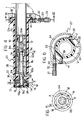
- Figure 4 is a section taken on the line IV-IV of Figure 3,
- Figure 5 is a section taken on the line V-V of Figure 4,
- Figure 6 is a section taken on the line VI-VI of Figure 4,
- Figure 7 is an exploded perspective view of the device according to the invention,
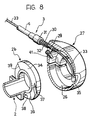
- Figure 8 is a partially-sectioned, exploded perspective view of a detail of the device according to the invention,
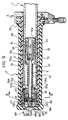
- Figure 9 is a longitudinal section of a device according to another embodiment of the invention,
- Figure 10 is a section taken on the line X-X of Figure 9,
- Figure 11 is a perspective view of the device of Figure 9, and
- Figure 12 is an exploded perspective view of the device of Figure 9.
- In Figures 1 and 2, a bicycle handlebar (of which only the right-hand end is visible) is indicated 1 and a rotatable hand-
grip 2 is associated therewith for operating the gears of the bicycle. The rotatable hand-grip 2, which will be described in detail below, is connected by a flexible cable transmission 3 (only thesheath 4 of which is visible in Figures 1 and 2) to the rear derailleur of the bicycle, which may be of any known type. Naturally, the invention is also applicable to the operation of the front derailleur of the bicycle. A device according to the invention can thus be provided at each end of the handlebar so that two twist-grips are provided for operating the rear derailleur and the front derailleur respectively. The rear derailleur of the bicycle is not shown in the drawings since, as already stated, it may be produced according to any known technique and does not fall within the scope of the present invention. Still according to conventional techniques, the rear derailleur controls the selective engagement of the bicycle chain with a set of sprockets associated with the rear wheel hub of the bicycle. Still according to conventional techniques, a spring is associated with the derailleur and tends to bias the chain towards the position in which it is engaged with the smallest-diameter sprocket corresponding to the highest gear ratio. As will be shown in more detail below, the rotatable hand-grip 2 is formed and arranged in such a way that it pulls the cable of thetransmission 3, causing the chain to be displaced towards the larger-diameter sprockets, when the hand-grip is rotated in the sense indicated by the arrow A in Figure 1. The chain is displaced towards the smaller-diameter sprockets corresponding to the higher gear ratios, however, when the hand-grip is rotated in the sense indicated by the arrow B in Figure 2. According to a further preferred characteristic, the device according to the invention may provide for awindow 5 formed in asleeve 6 fixed rigidly to the handlebar in correspondence with the inner end of the hand-grip 2. Thewindow 5 enables the display of a number which is indicative of the gear ratio engaged and is applied to one end of the hand-grip itself, as will be described in detail below. In the case of the embodiment illustrated in Figures 1 and 2, the numbers relate to the engagement of the first and sixth gear ratios respectively, as can be seen from the numbers displayed in thewindow 5. Naturally, the usual brake-operating lever 7 is mounted adjacent the hand-grip 2 and has a flexible cable transmission 8 for operating the brake. Moreover, in conventional manner, thebody 2 may be covered by a sheath defining the grip (not shown). - With reference to Figures 4 and 7, the hand-
grip 2 has a tubular plastics body with ahub 2a at one end and acollar 2b at the other end. The cylindrical cavity (indicated 2c) of the body of the hand-grip 2 houses thecylindrical end part 1a of the handlebar 1 with clearance. The body of the hand-grip 2 is mounted for rotation about its axis on theend 1a of the handlebar 1 by means of thehub 2a which slidingly engages atubular metal rod 9 fixed inside the handlebar 1 and having an end part which projects from the end of the handlebar. Therod 9 is fixed in thehandlebar 2 in the following manner. Theend 9f of the rod inside the handlebar has a larger diameter than the rest of therod 9 and has a threadedaxial hole 9a into the end of which the cylindrical cavity 9b of thetubular rod 9 opens. Ascrew 10 with aconical head 10a and ahexagonal cavity 10b in its threaded end is screwed into the threadedhole 9a. Thehexagonal cavity 10b enables thescrew 10 to be operated by means of akey 11 of hexagonal cross-section (Figure 3) which can be inserted through the cavity 9b in therod 9. - An
expansible bush 12, for example of plastics material, is interposed between theconical head 10a of thescrew 10 and theend surface 9c of the larger end portion of therod 9, which is also conical, and has conical end surfaces complementary to the surface of thehead 10a and thesurface 9c. When thescrew 10 is tightened in the threadedhole 9a, thehead 10a is brought towards thesurface 9c and thebush 12 consequently expands in the cavity in the handlebar 1. The assembly constituted by thescrew 10, thebush 12 and therod 9 is thus firmly fixed to the handlebar 1. In the particular embodiment shown, theexpansible bush 12 is made from a bush of plastics material by the formation of longitudinal cuts in the wall of the bush, extending from alternate ends of the bush for a distance less than the overall length of the bush. These cuts can be seen, indicated 13, in Figure 7. - The
free end 9d of thetubular rod 9 projects through thehub 2a into achamber 14 which is defined by thehub 2a, by atubular extension 15 of the hand-grip body 2 extending beyond thehub 2a, and by aplug 16 of plastics material screwed into thetubular appendage 15. - The indexing device for snap-locating the hand-grip in the various positions corresponding to the various gear ratios is mounted in the
chamber 14. In the embodiment illustrated, this device, generally indicated 17, is substantially of the type illustrated in Figures 12 and 13 of the same Applicant's Italian Patent Application No. 21647-A/86 relating to lever-operated gears. This type of indexing device is fitted in the gear lever marketed by the Applicant under the trade mark "Syncro". - With reference to Figures 4, 5 and 7, the
indexing device 17 includes two pin springs 18 each having anattachment end 18a fixed in a hole 19 (Figures 7 and 5) formed in the wall of the hand-grip 2 and anactive end 18b which engages the toothed surface of atoothed ring 20 fixed to therod 9. In the particular embodiment illustrated, thering 20 is fitted over abush 21 with two diametrally-opposedradial projections 22 which are housed in two seats 23 (one of which is partially visible in Figure 7) in thering 20. Thering 20 is thus connected for rotation with thebush 21. The latter is keyed in turn to thefree end 9d (Figure 7) of therod 9, the free end having two diametrally-opposed flat faces 9e (one of which is visible in Figure 7) which engage corresponding flat surfaces of the central hole in thebush 21. Thebush 21 and consequently thering 20 are thus prevented from rotating on therod 9. Axial fixing is achieved by means of a resilient ring 24 (Figure 4) which is fitted on therod 9 and holds thebush 21 and thering 20 against the wall of thehub 2a with the interposition of awasher 25. - By virtue of this arrangement, the
toothed ring 20 is fixed rigidly to therod 9 and hence to the handlebar 1, whilst the two pin springs 18 can move with the hand-grip 2. The active ends 18b of the pin springs 18 are urged by the resilient loading of the springs against the toothed surface of thering 20 so that the active ends snap-engage in successive spaces between the teeth of thering 20 when the hand-grip 2 is rotated. - The
plug 16 has acentral hole 16a which enables the key 11 to be inserted in order to lock thebush 12 in the handlebar 1 and release it therefrom, as described above. - The use of the indexing device described above provides, amongst other things, a characteristic advantage of the device which has already been described in the Applicant's previous Italian Patent Application No. 21647-A/86. In fact, if the cyclist changes the set of sprockets mounted on the rear wheel hub of the bicycle, the
toothed ring 20 can simply be replaced by a ring with a configuration such as to ensure the correct location of the chain in the various positions of engagement on the sprockets of the new set. - The
end collar 2b of the hand-grip 2 is housed in theskirt 26 of aclamp body 27 which is mounted around the handlebar 1 and is clamped thereto by the tightening of atangential screw 28 which is used to close the clamp body (Figure 7). Theclamp body 27 has a threadedhole 29 into which is screwed the threadedshank 30 of ascrew 31 to which the end part of the sheath 4 (Figures 4, 6, 8) of theflexible cable transmission 3 is fixed. According to a conventional technique, ahelical spring 32 is interposed between thescrew 31 and theclamp body 27. - The flexible metal cable, indicated 33, of the
flexible cable transmission 3 passes through thesheath 4, thescrew 31, theshank 30, and thehole 29 in theclamp body 27 and is housed in acircumferential groove 34 formed in thecollar 2b. The end of themetal cable 33 is fixed to abob 35 which is locked in aseat 36 defined by tworecesses 37 formed in the facing radial walls of thecollar 2b defining thegroove 34. One of therecesses 37 is visible in Figure 8. Thecollar 2b also has acircumferential track 38 whose angular extent corresponds to the maximum possible travel of the hand-grip and which is defined at its ends by twowalls 39 located in planes containing the axis of the hand-grip 2. Theclamp body 27 has a radial hole 40 (Figure 7) into which is screwed apin 41 which projects inwardly of the clamp body and engages thetrack 38. When the hand-grip is rotated, it operates the rear derailleur of the bicycle by means of theflexible cable 33. At the same time, thepin 41 slidably engages thetrack 38 and defines the travel-limit positions of the hand-grip by coming into contact with the tworespective end walls 39 of thetrack 38. - As already indicated above, the
collar 2b may have numbers on its peripheral surface indicative of the various gear ratios which can be engaged, whilst theskirt 26 of theclamp body 27 may have a window 5 (as in the embodiment shown in Figures 1 and 2) for displaying the gear ratio engaged. - When the cyclist acts on the hand-
grip 2 and rotates it about its axis, the hand-grip operates the rear derailleur of the bicycle by means of themetal cable 33. Theindexing device 17 enables the hand-grip to be snap-located in the various positions corresponding to the engagement of the various gear ratios. According to the conventional technique, the derailleur has a spring which tends to bias the derailleur (and hence the hand-grip 2 by means of the cable 33) towards the position corresponding to the engagement of the chain with the smallest-diameter sprocket (the highest gear ratio). This means that, when the chain is on the largest-diameter sprocket (the lowest gear ratio), the biassing force exerted by the derailleur spring is greatest. Thus, in this condition, there would be a risk that the cyclist could inadvertently change gear, particularly when he is travelling over rough ground and therefore needs to lean on the handlebar with a certain force. - In order to avoid this problem, the device according to the invention may provide a
helical spring 50 associated with the hand-grip 2. More precisely, thespring 50 is mounted coaxially around thetubular rod 9 and hasrespective tails rod 9 and to thehub 2a of the hand-grip 2. Thetail 50a is thus fixed relative to the handlebar 1, whilst thetail 50b is movable with the hand-grip 2. Thespring 50 is arranged so as to bias the hand-grip 2 in the opposite sense from the sense of biassing due to the derailleur spring. More precisely, thespring 50 tends to bias the hand-grip 2 in the sense indicated by the arrow A in Figure 1, that is, in the sense corresponding to the engagement of the chain on larger-diameter sprockets. The derailleur spring, on the other hand, biasses the hand-grip 2 in the sense indicated by the arrow B in Figure 2, which corresponds - as already stated - to the engagement of the chain on the smaller-diameter sprockets. The effects of the two springs reach an equilibrium condition when the chain is engaged on a sprocket intermediate the smallest-diameter sprocket and the largest -diameter sprocket. When the chain is in this position, no biassing force is exerted on the chain and there is thus a minimal risk of the gears being changed inadvertently since, to do so, it is necessary to overcome the entire force with which thespring 18 of theindexing device 17 opposes the rotation of the hand-grip 2. When the chain is on the largest-diameter sprocket, however, the chain is subject to a biassing force resulting from the opposing effects of the hand-grip spring 50 and the derailleur spring. In fact, thespring 50 is mounted in such a way that, even when the chain is on the largest-diameter sprocket, it exerts a biassing force on the derailleur which opposes that exerted by the derailleur spring. The biassing effect on the chain which results from the opposite effects of the two springs is less, in absolute terms, than that which occurs in conventional controls which are subject only to the biassing of the spring associated with the derailleur itself. The risk of the undesired operation of the gears is therefore greatly reduced. - Conversely, when the chain is on the smallest-diameter sprocket, it is subject to the biassing effect which results from the opposing effects of the derailleur spring and the hand-grip spring. In this case also, the resulting effect is insufficient, in practice, to give rise to the risk of an inadvertent gear change.
- As already indicated, the conformation of the toothed surface of the
ring 20 is selected in dependence on the sprockets which have to mesh with the chain. Moreover, the profiles of the teeth of thering 20 can be selected - at the design stage - so as to achieve the desired amount of effort to be applied to the hand-grip in order to operate the gears. Moreover, the profile of each tooth of thering 20 may be asymmetrical, that is, with one flank steeper than the other, in order to oppose the displacement of the chain under the biassing effects of the two springs of the derailleur and the hand-grip in a different manner according to whether the chain is on the large sprockets or on the small sprockets. This may be necessary if the resultant effect of the two springs has a different absolute value according to whether the chain is on the large sprockets or on the small sprockets. - According to another embodiment and with reference to Figures 9 to 12 (in which elements the same as or similar to those described above are indicated by the same reference numerals), the hand-
grip 2 is covered by an outer rubber sheath G and has a tubular body of plastics material in one end of which asupport bush 52 is inserted in abutment with internalradial appendages 53 in thecylindrical cavity 2c of the hand-grip 2. On each of its end faces, thebush 52 has three equiangularly-spacednotches 52a for keying the bush to the body of the hand-grip 2 in correspondence with the internalradial appendages 53 which are engaged in the notches. - The body of the hand-
grip 2 is mounted for rotation about its axis on theend 1a of the handlebar 1 by means of thesupport bush 52 whose central hole is engaged rotatably by thetubular rod 9. In this embodiment, therod 9 is fixed within the handlebar 1 by a pair ofrings 54 divided each into three portions held together byspring clips 55 and separated by acentral ring 56 with conical end surfaces complementary to the lateral surfaces of therings 54, the rings being interposed between theconical head 10a of thescrew 10 and theend surface 9c of thelarger end portion 9f of therod 9. Therings 54 also have conical end surfaces complementary to the surface of thehead 10a of the lockingscrew 10 and theend surface 9c of therod 9. The tightening of thescrew 10 in the threadedhole 9a by the operation of the key 11 causes thehead 10a to move towards thesurface 9c, consequently enlarging the split rings 54 within the cavity in the handlebar 1. The assembly constituted by thescrew 10, the split rings 54, thecentral ring 56 and therod 9 is thus fixed firmly to the handlebar 1. - The free end of the
tubular rod 9 projects from thesupport bush 52 into a chamber defined by thebush 52, the body of the hand-grip 2 and aplug 16b of plastics material havingaxial holes 57 for the passage oftie bolts 58 whose threaded ends 58a are adapted to cooperate with threadedholes 52b in thesupport bush 52. The tightening of thetie bolts 58 locks theplug 16b on the end of the body of the hand-grip 2 by virtue of the axial engagement between thesupport bush 52 and the internalradial appendages 53 of the body of the hand-grip 2. - On its lateral surface, the
plug 16b also has threeaxial ribs 72 whose shapes correspond to those of three internalaxial grooves 73 in the end of the tubular body of the hand-grip 2. Theplug 16b is keyed to the hand-grip 2 by the engagement of theribs 72 in thegrooves 73. - The
indexing device 17 is mounted in the chamber delimited by thebush 52 and, in this embodiment, includes three pin springs 18, theattachment end 18a of each of which is secured in ahole 19a in the correspondingprojection 53 formed on the inner wall of the hand-grip 2, its active end engaging the lateraltoothed surface 20b of atoothed ring 20a keyed by itsinternal hole 60 on the free end of thetubular rod 9, which has two diametrally-opposedflat faces 9e. When the device is in the assembled configuration, thetoothed ring 20a thus faces thesupport bush 52 with the interposition of a shapedwasher 25a which has outerradial tabs 25b and innerradial projections 25c whose functions will become clear from the following description. - The
toothed ring 20a also has anend face 20c with axial teeth oriented radially and corresponding to the teeth of thelateral surface 20b. A lockingring 62 which has axial projections 62a oriented radially towards thesurface 20c, as well as radial appendages 62b whose shapes correspond to those ofguides 63 in theplug 16b, is urged axially against theend surface 20c of thetoothed ring 20a in a resilient manner byBelleville washers 61. - The
plug 16b has a central threadedhole 16c into which is screwed a screw-adjustment element 64 which includes a manually-operable end 64a and from the centre of which arod 64b extends. Therod 64b has a threadedportion 65 connected to a circularcylindrical end portion 66 whose outside diameter corresponds to the diameters of the central holes in theBelleville washers 61. Anannular shoulder 67 is thus defined between the threadedportion 65 and thecylindrical portion 66 of therod 64b for cooperating with the first of the set ofBelleville washers 61. The screw-adjustment element 64 also has a central through-hole 68 and, at its manually-operable end 64a, atoothed end surface 69 which is adapted to define, with acorresponding spring 70 carried by theplug 16b, auxiliary position-indexing means for the screw-adjustment element 64. - Whilst the active ends 18b of the pin springs 18 are urged against the lateral
toothed surface 20b of thetoothed ring 20a by the resilient loading of the springs, the axial projections 62a of the lockingring 62 are urged against thetoothed end surface 20c of thering 20a by the resilient loading of theBelleville washers 61, between the lockingring 62 and theannual shoulder 67 of the screw-adjustment element 64 so that both the active ends 18b of the pin springs 18 and the axial projections 62a of the lockingring 62 snap-engage the spaces between the teeth of thering 20a successively when the hand-grip 2 is rotated. As it moves from one indexed position to another, the lockingring 62 slides axially in theplug 16b and is guided in this movement by the radial appendages 62b which slide in theguides 63 of the plug. - The
hole 68 in the screw-adjustment element 64 allows the key 11 to be inserted in order to clamp and release the split rings 54 inside the handlebar 1, as described above. - If the user wishes to increase or decrease the average torque necessary to cause the hand-grip to snap from one position to another, he acts on the operating
end 64a of the screw-adjustment element 64 which projects from both theplug 16b of the body of the hand-grip 2 and its outer rubber sheath G, its rotation being indexed by thespring 70 and thetoothed end surface 69. The rotation of theelement 64 varies the load exerted on the lockingring 62 by theBelleville washers 61 coaxial with therod portion 64b so that the force required to operate the hand-grip can be varied in dependence on the kind of terrain over which the bicycle is travelling. - The presence of the shaped
washer 25a interposed between thesupport bush 52 and thetoothed ring 20a limits the rotation of the hand-grip 2 to a predetermined angle. In fact, the tie-bolts 58 cooperate with the outerradial appendages 25b of thewasher 25a whose rotation is limited by the engagement between the innerradial appendages 25c and the diametrally opposedflat surfaces 9e at the free end of thetubular rod 9. At a predetermined angle of rotation, theradial appendages 25b abut the tie-bolts 58 and the internalradial appendages 25c come into contact with one of theflat surfaces 9e to stop the rotation of the hand-grip 2. - Naturally, the principle of the invention remaining the same, the details of construction and forms of embodiment may also be varied widely with respect to those described and illustrated purely by way of example, without thereby departing from the scope of the present invention.
Claims (20)
- A twist-grip device for operating the gears of a bicycle, including a hand-grip (2) mounted rotatably on a bicycle handlebar (1) and connected by a flexible cable transmission (3) to a bicycle derailleur which controls the selective engagement of a bicycle chain with a set of different sprockets arranged side by side, the derailleur being provided with first resilient means which tend to bias the derailleur towards an end position corresponding to the engagement of the chain with a first end sprocket of the set, the device also including indexing means (17) associated with the hand-grip (2) for snap-locating the hand-grip in the various positions corresponding to the engagement of the chain with the various sprockets, the device being characterised in that second resilient means (50) are associated with the hand-grip and bias the hand-grip in the opposite sense from the sense of biassing of the first resilient means of the bicycle derailleur so that the resultant effect of the first and second resilient means tends to bias the chain towards a position intermediate the two end sprockets of the set.
- A device according to Claim 1, characterised in that the indexing means include a toothed ring (20) fixed releasably to the handlebar and cooperating with a resilient engagement element (18) which is carried by the hand-grip (2) and is adapted to snap-engage the spaces between the teeth of the toothed ring (20) as a result of the rotation of the hand-grip (2) relative to the handlebar (1).
- A device according to Claim 2, characterised in that the indexing means (17) include two resilient engagement elements (18) in the form of pin springs each having a tail (18a) anchored to the wall of the hand-grip (2) and an end (18a) cooperating with the toothed ring (20).
- A device according to Claim 2, characterised in that a rod (9) is fixed inside the handlebar and includes an end portion (9d) which projects from the handlebar, to which the toothed ring (20) is connected and on which the body of the hand-grip (2) can rotate.
- A device according to Claim 4, characterised in that the body of the hand-grip (2) has a tubular configuration for housing the end portion of the handlebar (1) and includes a hub (2a) which is mounted rotatably on the end part of the rod (9), the body of the hand-grip (2) also including a tubular appendage which extends beyond the hub (2a) on the side opposite the handlebar (1) and defines a chamber (14) in which the indexing means (17) are located, the chamber being closed by a plug (16) screwed into the tubular appendage (15).
- A device according to Claim 5, characterised in that the end (9c) of the tubular rod (9) within the handlebar (1) has a threaded hole (9a), a screw (10) being screwed into the hole (9a) and an expansible bush (12) being interposed between the inner end (9c) of the rod (9) and the head (10a) of the screw (10) so that it expands against the inner wall of the handlebar (1) as a result of the tightening of the screw (10) in the threaded hole (9a).
- A device according to Claim 2, characterised in that the second resilient means are constituted by a helical spring (50) mounted coaxially around the rod (9) and having respective tails (50a, 50b) fixed to the body of the rod (9) and to the body of the hand-grip (2).
- A device according to Claim 1, characterised in that the inner end (2b) of the body of the hand-grip (2) has a collar which is housed in a skirt (26) of a clamp body (27) clamped around the handlebar (1), the collar (2b) having a circumferential track (38) whose angular extent corresponds to the maximum angular travel of the hand-grip and which houses a radial pin (41) carried by the clamp body (27) and projecting radially inwardly of the body so that the engagement of the pin (41) against the end surfaces of the circumferential track (38) defines the end positions of the angular travel of the hand-grip (2).
- A device according to Claim 8, characterised in that the clamp body (27) has a hole (29) for the fixing of the end screw (31) of the sheath (4) of the flexible cable transmission, the collar (2b) having a circumferential groove (34) which houses the flexible metal cable of the flexible cable transmission (3) and a seat (36) for an enlarged end portion (35) of the flexible cable (33).
- A device according to Claim 1, characterised in that it includes adjustment means (64, 16b, 61, 62, 62b, 20c) associated with the indexing means (18, 20b) and adapted to vary the torque needed to snap-rotate the hand-grip (2) between two successive positions.
- A device according to Claim 10, characterised in that the adjustment means include a screw-adjustment element (64) which is housed in a corresponding threaded seat (16c) in the hand-grip (16b, 2) and is adapted to vary the resilient loading of a corresponding engagement element (62) carried by the hand-grip (2) and adapted to snap-engage spaces between teeth (20c) of a toothed ring (20a) fixed removably to the handlebar (1).
- A device according to Claim 11, characterised in that the toothed ring (20a) has a toothed lateral surface (20b) for cooperating with resilient engagement elements (18) interposed between an internal wall of the hand-grip (2) and the toothed ring (20a) and an end surface (20c) which is also toothed for cooperating with corresponding end projections (62a) of a locking ring (62) keyed to the hand-grip (63, 16b, 2), resilient means (61) being interposed between the locking ring (62) and the screw-adjustment element (64) for urging the locking ring (62) against the end surface (20c) of the toothed ring (20a).
- A device according to Claim 12, characterised in that the screw element (64a) includes a manually-operable end (64a) with a toothed portion (69) which is adapted to define, with an auxiliary resilient engagement element (70) carried by the hand-grip (16b, 2), auxiliary position-indexing means for the screw element (64).
- A device according to Claim 12 or Claim 13, characterised in that the resilient means interposed between the locking ring (62) and the screw-adjustment element (64) comprise a plurality of Belleville washers (61) coaxial with the screw element (64).
- A device according to any one of Claims 10 to 14, characterised in that a rod (9) is anchored in the handlebar (1) and includes an end portion (9d) which projects from the handlebar, the toothed ring (20a) being connected to the end portion (9d) and the body of the hand-grip (2) being rotatable thereon.
- A device according to Claim 15, characterised in that, between the body of the hand-grip (2), which is tubular in order to house the end portion (1a) of the handlebar (1), and the rod (9), there is interposed a support bush (52) which is fixed to the hand-grip (2) and is rotatable on the end portion (9d) of the rod (9), one end (2a) of the hand-grip which extends beyond the support bush (52) having a closure plug (16b) keyed to the hand-grip (2).
- A device according to Claim 16, characterised in that the internal wall of the hand-grip (2) has radial projections (53) which support the resilient engagement elements (18) and are in abutment with the support bush (52), tie-bolts (58) being interposed between the bush (52) and the closure plug (16b) for fixing the support bush (52) and the closure plug (16b) to the hand-grip (2).
- A device according to Claim 17, characterised in that the threaded seat (16c) for the screw element (64) is in the centre of the closure plug (16b).
- A device according to any one of Claims 16 to 18, characterised in that the end (9c) of the tubular rod (9) within the handlebar (1) has a threaded hole (9a) into which a screw (10) is screwed, expansible rings (54) being interposed between the inner end (9c) of the rod (9) and the head of the screw (10) so that they expand against the inner wall of the handlebar (1) as a result of the tightening of the screw (10) in the threaded hole (9a), the screw-adjustment element (64) having a central through-hole (68) for the passage of a tightening tool (11).
- A bicycle handlebar including, at its ends, two operating devices according to any one of the preceding claims for operating the front derailleur and the rear derailleur of the bicycle respectively.
Applications Claiming Priority (4)
| Application Number | Priority Date | Filing Date | Title |
|---|---|---|---|
| IT06790589A IT1238133B (en) | 1989-10-20 | 1989-10-20 | Twist-grip device for operating gears of bicycle |
| IT6790589 | 1989-10-20 | ||
| IT6740390 | 1990-06-04 | ||
| IT67403A IT1241239B (en) | 1990-06-04 | 1990-06-04 | Indexed control device with rotary handle for bicycle gear shift |
Publications (2)
| Publication Number | Publication Date |
|---|---|
| EP0423779A1 EP0423779A1 (en) | 1991-04-24 |
| EP0423779B1 true EP0423779B1 (en) | 1994-04-20 |
Family
ID=26329767
Family Applications (1)
| Application Number | Title | Priority Date | Filing Date |
|---|---|---|---|
| EP90119957A Expired - Lifetime EP0423779B1 (en) | 1989-10-20 | 1990-10-18 | A twist-grip device for operating the gears of a bicycle |
Country Status (4)
| Country | Link |
|---|---|
| US (1) | US5134897A (en) |
| EP (1) | EP0423779B1 (en) |
| JP (1) | JP2951391B2 (en) |
| DE (1) | DE69008298T2 (en) |
Families Citing this family (63)
| Publication number | Priority date | Publication date | Assignee | Title |
|---|---|---|---|---|
| JPH04260889A (en) * | 1991-02-13 | 1992-09-16 | Maeda Kogyo Kk | Speed change operating device for bicycle |
| US5102372A (en) * | 1991-03-20 | 1992-04-07 | Sram Corporation | Bicycle derailleur cable actuating system |
| JPH04342684A (en) * | 1991-05-17 | 1992-11-30 | Maeda Kogyo Kk | Derailer for bicycle |
| JPH0820378A (en) * | 1991-11-11 | 1996-01-23 | Mori San Tour:Kk | Speed change mechanism for bicycle and speed changing method therwith |
| JP3359663B2 (en) * | 1992-09-21 | 2002-12-24 | 株式会社シマノ | Brake lever device with gearshift device for bicycle |
| US5241877A (en) * | 1992-12-04 | 1993-09-07 | Chen Chun Hsung | Gear selector |
| JPH06199270A (en) * | 1992-12-28 | 1994-07-19 | Mori San Tsuaa:Kk | Gear shift device for bicycle |
| JPH06239287A (en) * | 1993-02-12 | 1994-08-30 | Mori San Tsuaa:Kk | Transmission operation device for bicycle |
| EP0683092A1 (en) * | 1993-04-01 | 1995-11-22 | Guy V.O. Bulkeley | Motorcycle control lever connector |
| JP3644602B2 (en) * | 1994-02-23 | 2005-05-11 | 株式会社シマノ | Bicycle shifting operation device |
| US6199447B1 (en) | 1994-03-07 | 2001-03-13 | Sram Corporation | Bulbous grip for rotatable bicycle gear shifter |
| US5564316A (en) * | 1994-03-07 | 1996-10-15 | Sram Corporation | Nubbed grip for rotatable bicycle gear shifter |
| US5476019A (en) * | 1994-03-07 | 1995-12-19 | Sram Corporation | Rotatable handgrip actuating system |
| JPH0844450A (en) * | 1994-03-07 | 1996-02-16 | Sram Corp | Rotation-type grip operating device and its rotation stop mechanism |
| DE4420273A1 (en) * | 1994-06-10 | 1995-12-14 | Helmig Hans Gmbh | Twist grip for operating bicycle gear shifts |
| US5666859A (en) * | 1994-12-02 | 1997-09-16 | Fichtel & Sachs Ag | Latching shifter for a bicycle transmission |
| US5823058A (en) * | 1994-12-02 | 1998-10-20 | Mannesmann Sachs Ag | Twist-grip shifter for bicycles and a bicycle having a twist-grip shifter |
| US5799541A (en) * | 1994-12-02 | 1998-09-01 | Fichtel & Sachs Ag | Twist-grip shifter for bicycles and a bicycle having a twist-grip shifter |
| EP0718185B1 (en) * | 1994-12-20 | 2000-03-22 | Shimano Inc. | Bicycle shift control device with balanced spring tension |
| US5620383A (en) * | 1995-02-06 | 1997-04-15 | Sram Corporation | Bicycle derailleur and actuating system |
| EP0759393B1 (en) * | 1995-03-13 | 2002-08-21 | Sakae Co., Ltd. | Bicycle and speed change operating device for the same |
| DE69601337T2 (en) * | 1995-03-31 | 1999-09-16 | Sugino Cycle Industries, Ltd. | CONTROL DEVICE FOR A BICYCLE GEAR |
| CA2253892A1 (en) | 1995-08-03 | 1997-02-20 | Franck Savard | Stress compensation device for the cable-type control of a derailleur, particularly for a bicycle |
| FR2737463B1 (en) * | 1995-08-03 | 1999-04-30 | Franck Savard | STRESS COMPENSATION DEVICE FOR A WIRE DERAILLEUR DRIVE, PARTICULARLY FOR A BIKE |
| US6055882A (en) * | 1995-09-20 | 2000-05-02 | Fichtel & Sachs Ag | Twist-grip shifter for bicycles |
| IT1290791B1 (en) * | 1995-10-31 | 1998-12-10 | Campagnolo Srl | CONTROL DEVICE OF A BICYCLE DERAILLEUR, WITH CONTROL UNIT MOUNTED ON THE HANDLEBAR OF THE BICYCLE. |
| US5678455A (en) * | 1996-02-15 | 1997-10-21 | Shimano, Inc. | Bar-end shifting device |
| JP3678496B2 (en) * | 1996-05-30 | 2005-08-03 | 株式会社シマノ | Bicycle shifting operation device |
| US5682963A (en) * | 1996-07-12 | 1997-11-04 | Tang; Jen-Hui | Brake assembly for a bicycle |
| DE19651577C2 (en) * | 1996-12-12 | 1999-02-18 | Sram De Gmbh | Twist shifter for bicycle transmissions |
| AT406365B (en) * | 1997-02-21 | 2000-04-25 | Josef Prajczer | BICYCLE GEAR |
| US5784924A (en) * | 1997-03-25 | 1998-07-28 | Wu; Mu-Chuan | Gearshift adjusting device |
| US5860326A (en) * | 1997-03-26 | 1999-01-19 | Corporacion Resentel S.A. De C.V. | Combined speed shifter and brake handle assembly |
| US6484603B2 (en) * | 1997-12-05 | 2002-11-26 | Sram Deutschland Gmbh | Selector for a bicycle gear mechanism |
| DE19922327A1 (en) | 1999-05-14 | 2000-11-16 | Sram De Gmbh | Access tag for gearchange control on bicycle has a soft plastic window attached to the gearchange housing by a flexible tie |
| US6293882B1 (en) | 1999-12-10 | 2001-09-25 | Shimano, Inc. | Operating force compensating apparatus for a bicycle transmission |
| US6328138B1 (en) | 1999-12-10 | 2001-12-11 | Shimano Inc. | Brake operating device with modulator |
| US6244415B1 (en) | 1999-12-30 | 2001-06-12 | Shimano, Inc. | Motor controlled shift control device including an idler gear for a bicycle transmission |
| DE10013262A1 (en) * | 2000-03-17 | 2001-09-20 | Sram De Gmbh | One-way power transmission |
| DE10025883A1 (en) * | 2000-05-25 | 2001-11-29 | Sram De Gmbh | Integrated twist grip switch |
| KR20010110061A (en) * | 2000-05-30 | 2001-12-12 | 마재열 | Apparatus for controlling a speed changing apparatus for bicycles |
| ITTO20010010A1 (en) * | 2001-01-11 | 2002-07-11 | Campagnolo Srl | INTEGRATED GEARBOX AND BRAKE CONTROL GROUP FOR A BICYCLE. |
| US20030140725A1 (en) * | 2001-02-22 | 2003-07-31 | Liu Jen-Chih | Manual shift mechanism of a bicycle |
| US6571726B2 (en) * | 2001-04-27 | 2003-06-03 | Sunrace Roots Enterprise Co., Ltd. | Device for monitoring gear lever position |
| US6488130B1 (en) * | 2001-05-10 | 2002-12-03 | John Karl Bermel | Twist-grip brake for a cargo portage device |
| US6792825B2 (en) * | 2001-06-28 | 2004-09-21 | Shimano Inc. | Bicycle shift control device |
| DE10132000A1 (en) * | 2001-07-02 | 2003-01-16 | Sram De Gmbh | Actuator housing |
| CN1297440C (en) * | 2002-04-10 | 2007-01-31 | 什拉姆公司 | Bicycle gear indicator mechanism |
| DE10216168A1 (en) * | 2002-04-12 | 2003-10-23 | Sram De Gmbh | Childs bicycle twist grip comprises cable reel of small diameter at handlebar end with cable guide curving to center and integral to curved hand guard. |
| US7350436B2 (en) * | 2004-03-29 | 2008-04-01 | Shimano, Inc. | Electrical bicycle shift control device |
| US7793751B2 (en) * | 2005-04-01 | 2010-09-14 | Honda Motor Company, Ltd. | Vehicles including control assemblies having rotatable control knobs |
| DE102006060345A1 (en) * | 2006-12-20 | 2008-06-26 | Gustav Magenwirth Gmbh & Co. Kg | handle tube |
| JP5311556B2 (en) * | 2008-12-25 | 2013-10-09 | 朝日電装株式会社 | Throttle grip device |
| JP5448148B2 (en) * | 2009-06-05 | 2014-03-19 | 朝日電装株式会社 | Throttle grip device |
| US9651138B2 (en) | 2011-09-30 | 2017-05-16 | Mtd Products Inc. | Speed control assembly for a self-propelled walk-behind lawn mower |
| CN103879500A (en) * | 2013-12-20 | 2014-06-25 | 柳州译海网络科技有限公司 | Electrocar faucet with anti-falling speed regulating handles |
| CN103707984A (en) * | 2013-12-20 | 2014-04-09 | 柳州译海网络科技有限公司 | Falling-preventing speed-adjusting handle of electric car |
| IT201600111274A1 (en) * | 2016-11-04 | 2018-05-04 | Freni Brembo Spa | Lever device |
| IT201600120097A1 (en) * | 2016-11-28 | 2018-05-28 | Giovanni Conte | MOTORIZED WHEELCHAIR FOR DISABLED OR ELDERLY. |
| DE102018001253A1 (en) * | 2017-03-20 | 2018-09-20 | Sram Deutschland Gmbh | Rear derailleur for coaxial mounting |
| US11052963B2 (en) | 2018-01-02 | 2021-07-06 | Thomas Erdmann | Throttle tube with radial bearing for ride by wire throttle systems |
| US10668974B2 (en) * | 2018-01-02 | 2020-06-02 | Thomas Erdmann | Throttle tube with cable side radial bearing located inline with cable cam housing |
| CN115768652A (en) * | 2020-06-28 | 2023-03-07 | Tvs电机股份有限公司 | Motor vehicle |
Family Cites Families (9)
| Publication number | Priority date | Publication date | Assignee | Title |
|---|---|---|---|---|
| BE537784A (en) * | 1900-01-01 | |||
| DE864813C (en) * | 1951-06-16 | 1953-01-29 | Gustav Magenwirth Komm Ges | Rotary switch handle for motorcycles |
| US3752006A (en) * | 1972-07-24 | 1973-08-14 | C Bartlett | Throttle assist mechanism for motorcycle |
| JPS5247238A (en) * | 1975-10-13 | 1977-04-14 | Shimano Industrial Co | External transmission |
| FR2510508A1 (en) * | 1979-06-15 | 1983-02-04 | Saker | Selective speed motorcycle twist grip - has two ramps on throttle barrel selectively engaged by cable |
| DE3012034A1 (en) * | 1980-03-28 | 1981-10-15 | Gustav Magenwirth Gmbh & Co, 7432 Urach | THROTTLE GRIP FOR THE HANDLEBAR OF A MOTOR-DRIVEN TWO-WHEELED VEHICLE |
| FR2575434B1 (en) * | 1984-12-28 | 1989-05-19 | Huret & Fils | CONTROL DEVICE, ESPECIALLY FOR A CYCLE DERAILLEUR |
| DE3727505C2 (en) * | 1986-09-09 | 1996-10-10 | Campagnolo Spa | Gear selector for a bicycle gear shift |
| DE8708206U1 (en) * | 1987-06-11 | 1987-08-06 | Unseld, Hans-Peter, Dr., 7800 Freiburg | Combined brake and gear shift twist grip |
-
1990
- 1990-10-18 EP EP90119957A patent/EP0423779B1/en not_active Expired - Lifetime
- 1990-10-18 US US07/600,375 patent/US5134897A/en not_active Expired - Lifetime
- 1990-10-18 DE DE69008298T patent/DE69008298T2/en not_active Expired - Fee Related
- 1990-10-19 JP JP2283241A patent/JP2951391B2/en not_active Expired - Lifetime
Also Published As
| Publication number | Publication date |
|---|---|
| US5134897A (en) | 1992-08-04 |
| EP0423779A1 (en) | 1991-04-24 |
| JPH03176290A (en) | 1991-07-31 |
| JP2951391B2 (en) | 1999-09-20 |
| DE69008298D1 (en) | 1994-05-26 |
| DE69008298T2 (en) | 1994-08-04 |
Similar Documents
| Publication | Publication Date | Title |
|---|---|---|
| US5134897A (en) | Twist-grip device for operating the gears of a bicycle | |
| US5390565A (en) | Bicycle speed change system, bicycle speed change method and bicycle speed change operation assembly | |
| EP0916570B1 (en) | Cable adjustment device | |
| EP1213157B1 (en) | Bicycle hub with threaded spacer and detachable freewheel | |
| EP1043221B1 (en) | Freewheel for a bicycle | |
| US6409281B1 (en) | Bicycle hub with spacer and detachable freewheel | |
| US9187149B2 (en) | Bicycle derailleur with rotation resistance and resistance control | |
| US6067875A (en) | Handlebar-mounted bicycle shifter system and method | |
| US20170050465A1 (en) | Rear Hub and Bicycle Axle | |
| US5033991A (en) | Automatic derailleur shifter | |
| EP1040993A2 (en) | Rotatable seal assembly for a bicycle hub transmission | |
| EP1288118B1 (en) | Brake operating device with modulator | |
| US5272936A (en) | Bicycle headset | |
| US5125489A (en) | High-torque dual-purpose hub assembly for the rear wheel of a multispeed bicycle | |
| GB1592078A (en) | Multi-speed hub for a bicycle | |
| US6405613B1 (en) | Cable saver mechanism | |
| EP1935770B1 (en) | Bicycle component mounting structure | |
| US4348916A (en) | Brake operating device for a bicycle | |
| JPH09240567A (en) | Control device for bicycle transmission | |
| US20210061403A1 (en) | Grip system | |
| EP0422240B1 (en) | Brake for bicycle | |
| FR2594403A1 (en) | LEVER OF CHANGE OF SPEED FOR BICYCLE | |
| US9446813B2 (en) | Bicycle shifter | |
| US6029780A (en) | Brakes for bicycles and other chain driven mechanisms | |
| EP4306398B1 (en) | Quick-release for bicycles |
Legal Events
| Date | Code | Title | Description |
|---|---|---|---|
| PUAI | Public reference made under article 153(3) epc to a published international application that has entered the european phase |
Free format text: ORIGINAL CODE: 0009012 |
|
| AK | Designated contracting states |
Kind code of ref document: A1 Designated state(s): DE ES FR |
|
| 17P | Request for examination filed |
Effective date: 19911015 |
|
| 17Q | First examination report despatched |
Effective date: 19930713 |
|
| GRAA | (expected) grant |
Free format text: ORIGINAL CODE: 0009210 |
|
| AK | Designated contracting states |
Kind code of ref document: B1 Designated state(s): DE ES FR |
|
| PG25 | Lapsed in a contracting state [announced via postgrant information from national office to epo] |
Ref country code: ES Free format text: THE PATENT HAS BEEN ANNULLED BY A DECISION OF A NATIONAL AUTHORITY Effective date: 19940420 |
|
| REF | Corresponds to: |
Ref document number: 69008298 Country of ref document: DE Date of ref document: 19940526 |
|
| ET | Fr: translation filed | ||
| PLBE | No opposition filed within time limit |
Free format text: ORIGINAL CODE: 0009261 |
|
| STAA | Information on the status of an ep patent application or granted ep patent |
Free format text: STATUS: NO OPPOSITION FILED WITHIN TIME LIMIT |
|
| 26N | No opposition filed | ||
| PG25 | Lapsed in a contracting state [announced via postgrant information from national office to epo] |
Ref country code: FR Effective date: 19950630 |
|
| PG25 | Lapsed in a contracting state [announced via postgrant information from national office to epo] |
Ref country code: DE Effective date: 19950701 |
|
| REG | Reference to a national code |
Ref country code: FR Ref legal event code: ST |