EP0423708B1 - Method and apparatus for thermally recording data in a recording medium - Google Patents
Method and apparatus for thermally recording data in a recording medium Download PDFInfo
- Publication number
- EP0423708B1 EP0423708B1 EP19900119808 EP90119808A EP0423708B1 EP 0423708 B1 EP0423708 B1 EP 0423708B1 EP 19900119808 EP19900119808 EP 19900119808 EP 90119808 A EP90119808 A EP 90119808A EP 0423708 B1 EP0423708 B1 EP 0423708B1
- Authority
- EP
- European Patent Office
- Prior art keywords
- temperature
- heating
- recording
- heating resistor
- heat
- Prior art date
- Legal status (The legal status is an assumption and is not a legal conclusion. Google has not performed a legal analysis and makes no representation as to the accuracy of the status listed.)
- Expired - Lifetime
Links
Images


Classifications
-
- B—PERFORMING OPERATIONS; TRANSPORTING
- B41—PRINTING; LINING MACHINES; TYPEWRITERS; STAMPS
- B41J—TYPEWRITERS; SELECTIVE PRINTING MECHANISMS, i.e. MECHANISMS PRINTING OTHERWISE THAN FROM A FORME; CORRECTION OF TYPOGRAPHICAL ERRORS
- B41J2/00—Typewriters or selective printing mechanisms characterised by the printing or marking process for which they are designed
- B41J2/315—Typewriters or selective printing mechanisms characterised by the printing or marking process for which they are designed characterised by selective application of heat to a heat sensitive printing or impression-transfer material
- B41J2/32—Typewriters or selective printing mechanisms characterised by the printing or marking process for which they are designed characterised by selective application of heat to a heat sensitive printing or impression-transfer material using thermal heads
- B41J2/35—Typewriters or selective printing mechanisms characterised by the printing or marking process for which they are designed characterised by selective application of heat to a heat sensitive printing or impression-transfer material using thermal heads providing current or voltage to the thermal head
- B41J2/355—Control circuits for heating-element selection
- B41J2/3555—Historical control
-
- B—PERFORMING OPERATIONS; TRANSPORTING
- B41—PRINTING; LINING MACHINES; TYPEWRITERS; STAMPS
- B41J—TYPEWRITERS; SELECTIVE PRINTING MECHANISMS, i.e. MECHANISMS PRINTING OTHERWISE THAN FROM A FORME; CORRECTION OF TYPOGRAPHICAL ERRORS
- B41J2/00—Typewriters or selective printing mechanisms characterised by the printing or marking process for which they are designed
- B41J2/315—Typewriters or selective printing mechanisms characterised by the printing or marking process for which they are designed characterised by selective application of heat to a heat sensitive printing or impression-transfer material
- B41J2/32—Typewriters or selective printing mechanisms characterised by the printing or marking process for which they are designed characterised by selective application of heat to a heat sensitive printing or impression-transfer material using thermal heads
- B41J2/375—Protection arrangements against overheating
Landscapes
- Electronic Switches (AREA)
Description
- The present invention relates to a method and an apparatus for thermally recording information in a recording medium and, more particularly, for realizing an excellent recording by controlling the peak temperature of heating resistor as it does not exceed the specific temperature.
- Conventional apparatuses for recording information in the recording medium thermally utilize a resistor of a metallic compound such as ruthenium oxide or tantalum nitrido, or a cermet resistor prepared by dispersing an insulator such as silicon oxide into a refractory metal such as tantalum in the heating resistor of the thermal head.
- Also ceramic materiales comprising electronically conducting oxides with high temperature metallic/non-metallic transition phases are known (Encyclopedia of Chemical Technology, third edition, Vol. 10, pages 1 - 30) the resistivity of which rises rapidly thus forming a resistor material with a positive temperature coefficient.
- When a proper voltage is applied to the aforementioned heating resistor of the thermal head using such a ceramic material, an electric current flows through the heating resistor to generate the Joule heat, and this state is maintained for a constant time to give heat-sensitive recording paper a thermal energy necessary for the recording. The energy of the Joule heat generated by the aforementioned heating resistor is determined in dependence upon the resistance of the heating resistor, the applied voltage and the time period for applying the voltage.
- A conventional thermal recording apparatus as described in JP-A-62/181 162 uses BaTiO₃ ceramic material to prevent overheating. The material has its temperature transition phase between 50°C and 100°C and so adjusts the applied voltage or the time period for applying the voltage according to the heat sensitivity of the heat-sensitive papers used, the background temperature around the heating resistor, the temperature of the recording medium itself and the thermal conductivity which the thermal energy generated by the heating resistor is transmitted from the heating resistor to the heat-sensitive paper that it obtains the optimum recording quality and the desired recording density.
- On the other hand, the powered transfer recording apparatus comprises an ink donor sheet having a power heating resistor layer which consists of carbon paint and a power supply head. When the power heating resistor layer is powered by the power supply head, the ink donor sheet is heated by the thermal energy generated by the power heating resistor layer so that the ink may be melted or sublimated and transferred to the recording medium. It so adjusts the applied voltage or the voltage applying time period according to the sheet resistance of the powered heating resistor layer, the temperature of the ink donor sheet and the electrode temperature of the power supply head that it makes the thermal energy generated the powered heating resistor layer most suitable so as to obtain the optimum recording quality and the desired recording density.
- In the thermal recording method of the prior art, for the following reasons, the adjustment of recording thermal energy according to the voltage and the pulse width to be applied to the heating resistor is seriously troublesome to raise the production cost for the recording apparatus.
- The thermal energy to be generated in the heating resistor by applying voltage pulses can be determined in dependence upon the voltage or the pulse width of the applied pulses, as has been described in JP-A-61/035265, which discloses the rise of resistivity due to the positive resistance characteristic of a thermister or posister series-connected to the heating resistor, if the resistance is rised up over a certain temperature. Despite of this fact, however, the temperature of the heating resistor will fluctuate with the pulse applying histories such as the period of applying the pulse and the number of the pulse applied continuously, the thermal histories of the heating resistor, or the temperature of the supporting substrate of the thermal head or the environments.
- The thermal recording mechanism depends directly not upon the level of the thermal energy generated by the heating resistor but upon the temperature of the coloring layer of the heat-sensitive recording paper or the ink layer, i.e., the temperature of the heating resistor. If, therefore, it uniforms the temperature of the heating resistor at the heating time so as to achieve a uniform thermal recording to the heat-sensitive papers or the like, it needs to collect or predict the thermal data of the environment and histories in which the heating resistor is placed at the instant of heating. It has to so adjust and determine the voltage value or the pulse width of the applied voltage based on those data that the temperature of the heating resistor raises to the desired temperature.
- The data collecting means, data predicting means and recording condition deciding means exert seriously high loads upon the hardwares such as a variety of temperature sensors for detecting the temperature of the thermal head substrate of the environment, memories for storing the past recorded data so as to grasp the recording histories, simulators such as a thermal equivalent circuit for predicting the thermal states, and the CPU and gate circuits for processing data. Seriously complex softwares are also required for supporting those hardwares. Especially, either a large-sized highly precise thermal recording apparatus having a plurality of heating resistors or an apparatus for recording data with continuous tone of density has to process massive data so that it cannot avoid the increase in the size and price while sacrificing the recording quality. On the other hand, the processing time for collecting and predicting the data and deciding the recording conditions is restricted by the CPU or the like to trouble the high-speed recording.
- Moreover, the thermal head is usually formed with a glazed layer as a heat insulating layer for enhancing the thermal efficiency. This glazed layer is formed by a thick film process so that its thickness disperses over ± 20% of the average value of the thickness so that the heat insulating effect by the glazed layer randomly disperses among the individual thermal heads. No matter how accurately the data of the thermal environment of the heating resistor might be grasped and processed to decide the individual recording condition, as has been described herein-before, the highly accurate exothermic temperature control would be blocked by the dispersion of the thermal characteristics of the thermal heads. If a more highly accurate control of the exothermic temperature is to be accomplished, the dispersion of the thermal characteristics of the individual thermal heads also has to be incorporated as the control parameter so that the mass-productivity has to be seriously sacrificed by adjusting the recording apparatus one by one. If it is considered to replace the thermal heads in the recording apparatus because of their troubles or lifetimes, it is almost difficult to adjust the settings of the recording apparatus for the individual characteristics of the thermal heads. The dispersions of the thermal capacity and the thermal resistance also depend upon the periphery of the heating resistor layer in the powered thermal recording, thus raising problems similar to those of the afore-mentioned case of the thermal head.
- An object of the present invention is to provide an improved method and apparatus for uniformly controlling a temperature of a heating resistor on which the thermal recording mechanism depends.
- Another object of the present invention is to provide an improved method and apparatus for recording continuous tone data according to a period of time for holding peak temperature of a heating resistor.
- To realize above objects, the present invention provides the features as claimed in
claim 1. - The utilization of the invention gives the thermal head itself a temperature selfcontrol function to prevent the temperature of the heating resistor from exceeding a predetermined level.
- More particularly, there is provided a monitor, which performs a temperature change equal or similar to that of the heating resistor in synchronism with both the temperature rise of the heating resistor energized and the temperature drop of the heating resistor due to the interruption of the power-supply to the heating resistor, in the path which the electric current flows to the heating resistor.
- It makes the monitor of a material of phase transition having its electric conductivity changed metallic at a lower temperature across a predetermined temperature range and non-metallic at a higher temperature. When the temperature of the heating resistor is raised to reach the predetermined temperature, i.e., the metallic/non-metallic phase transition temperature by applying the voltage to the heating resistor so as to generate the Joule heat, the phase transition material has its resistance increased substantially to that of an insulator or semiconductor to interrupt the current substantially. Since thyristors are series-connected to the monitor and heating resistor means the electric current through the heating resistors is interrupted as soon as the phase transition temperature is reached and stays stand-by for the subsequent input impulse applied to the thyristor. As a result the heating resistors automatically interrupt their heat generation, the temperature of the heating resistor is not raised to exceed the phase transition temperature so that its peak temperature can be uniformly controlled within the phase transition temperature range. By this uniform control of the peak temperature, the thermal recording can be uniformed. Further, by the control of a period of time for holding the peak temperature, it can achive a stable and excellently reproducible recording of contenious tone data.
- Further more, the heating resistor itself may be made of the material of phase transition.
-
- Fig. 1 is a plane view of a thermal head;
- Figs. 2 and 3 are graphical representations showing the heating temperature characteristics of the thermal head shown in Fig. 1;
- Figs. 4, 5, 6 and 11 are diagrammatic renditions of a burn point area of a thermal head; Figs. 4(A), 5, 6(A) and 11 are partially plane views and Figs. 4(B) and 6(B) are partially sectional views of the thermal head shown in Figs. 4(A) and 6(A);
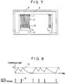
- Fig. 7 is a plane view of an embodiment of the thermal head of the present invention;
- Fig. 8 is a graphical representation showing the heating temperature characteristics of the thermal head shown in Fig. 7;
- Fig. 9 is a block diagram of an embodiment of a driving control circuit for carrying out the method of the present invention;
- Fig. 10 is a timing chart showing control timing of the driving control circuit shown in Fig. 9;
- Fig. 12 is a graphical representation showing the heating temperature characteristics of the thermal head of the present invention;
- Fig. 13 is a graphical representation showing the contenious tone heating temperature characteristics of a thermal head;
- Fig. 14 is a graphical representation showing the temperature dependency of the linear resistance of the material exhibiting the metallic/non-metallic phase transition;
- Figs. 15 and 17 are partially sectional views of apparatus for carrying the method of the present invention;
- Fig. 16 is a partially perspective illustration of the thermal recording head to be used in the method of the present invention; and
- Fig. 18 is a partially perspective illustration of the power heating sheet to be used in the method of the present invention.
- The invention will now be described with reference to the accompanying drawings representing an embodiment thereof.
- Fig. 1 is a plan view of an embodiment of a thermal head. This thermal head is constructed by forming thin-
film heating resistors 1, which are made of a material having metallic characteristics of electric conductivity at a lower temperature across about 300°C and non-metallic characteristics at a higher temperature such as vanadium oxide doped with about 0.1% of Cr to V, over asubstrate 6 made of glazed alumina ceramics, by connecting one-side terminals of theheating resistors 1 withindividual electrodes 2 and the other-side terminals with a firstcommon electrode 3, and by connecting theindividual electrodes 2 withcurrent switching elements 4 such as transistors. Numeral 5 designates a second common electrode connected with theswitching elements 4. The thermal head need not be equipped with theswitching elements 4 and the secondcommon electrode 5 but may be separately provided at the recording apparatus. - The first
common electrode 3 is fed with a plus potential whereas the secondcommon electrode 5 is fed with a minus potential, and voltage pulses are applied to theaforementioned heating resistors 1 by switching theswitching elements 4. If the voltage pulses are applied to theheating resistors 1, a suitable power consumption is caused by the applied voltage and the resistances of theheating resistors 1, as in the thermal head in the thermal recording of the prior art, to generate the Joule heat so that the temperature rise of theheating resistors 1 is started. - Fig. 2 is a graphical representation showing the time changes of the surface temperature of the
heating resistors 1 according to a pulse applying in the thermal head of Fig. 1. In Fig. 2, letter Tc designates the temperature of the metallic/non-metallic phase transition at the electric conductivity of the heating resistors. Letter ton designates the time to start the applying of pulses. Letter tp designates the time at which the surface temperature of the heating resistors reaches the above-specified phase transition temperature (Tc). Letter toff designates the time to end the pulse applying. For the period between the time tp and the time toff, theheating resistors 1 repeat the metallic/non-metallic phase transitions from the higher to lower temperatures and vice versa so that their surface temperature calms down in the vicinity of the aforementioned phase transition temperature TC. The actual temperature of the heating resistor may be raised to a slightly higher level than the level TC by either the heat capacity of the structural member in the periphery of the heating resistors themselves or the thermal inertia due to the thermal resistance. The surface temperature of the heating resistors reaches the level TC of about 300°C for a time period as short as about 0.5 millisecs from the time ton unless a heat absorber such as heat-sensitive papers are brought into contact with the heating resistors, in case theheating resistors 1 have an area of 0.015 mm² corresponding to the heating resistor density of 8 dots/mm, in case theheating resistors 1 have a resistance of about 1,000 Ω at the lower temperature, and in case the applied voltage is 20 V. This time period is individually different for the structures of the thermal head because the thermal characteristics such as the thermal resistance or heat capacity of the vicinity of the heating resistors are different in dependence upon the glazing thickness of theglazed substrate 6 of the thermal head or the thickness of the protecting layer coating the surfaces of theheating resistors 1. Since, however, the peak temperature of theheating resistors 1 is determined by the aforementioned phase-transition temperature TC of the material making the heating resistors, it does not depend upon the aforementioned thermal characteristics of the thermal head or the structure of the thermal head. - Further, the dispersion of the thermal characteristics, which the thermal head has, appears as the temperature rising gradient from the time ton to the time tp, i.e., at the time tp.
- In the direct heat-sensitive recording system, the color developing mechanism is the chemical reaction of a coloring agent due to the heat and the reaction rate depends upon the temperature. In the thermal transfer recording system, the recording mechanism is the physical phase change such as the melting or sublimation of the ink and is dominated by the temperature of the ink. Therefore, the effect of the dispersion of the thermal characteristics on the recording characteristics is far smaller than those of the prior art in which the peak temperature of the heating resistor fluctuates.
- On the other hand, the dispersion of the resistance of the heating resistors may exist in not only the thermal head in the thermal recording of the prior art but also the thermal head in the thermal recording of the present invention in dependence upon the thickness of the resistive films. However, this dispersion appears only as that of the period from the time ton to the time tp in the thermal head in the present invention so that the peak temperature of the heating resistor is unvaried. If it is intended to strictly reduce the dispersion of the temperature rising gradient, i.e., the dispersion of the time tp due to the resistance dispersion of the heating resistors, the applied voltage may be adjusted and set to uniform the electric power according to the magnitude of the resistance of the heating resistors in the metallic electric conductivity phase of the heating resistors at the lower temperature.
- As has been described hereinbefore, the effect of the thermal characteristic dispersion and resistance dispersion of the thermal head upon the recording characteristics are remarkably small in the case of the thermal head in the present invention. For the larger applied pulse width, i.e., the longer time period from the time ton to the time toff of Fig. 2, as compared with the temperature rising period from the time ton to the time tp, the changing and dispersing rates of the holding time period (toff - tp) of the peak temperature, which is the most contributable to the recording characteristics, are reduced the more to improve the recording quality the better.
- As described above, the temperature for the metallic/non-metallic phase transition of the heating resistors is set at about 300°C. In the case of a thermal head required for a higher recording speed, however, the heating resistors used have a higher phase transition temperature of 400 to 450 °C so that their resistance may be lowered (or the applied voltage may be raised) to increase the electric power. Then, at a higher temperature rising rate and at a higher peak temperature, the coloring reaction of the heat-sensitive paper is sufficiently effected for a shorter time so that the peak temperature holding time can be retained for a shorter applied pulse width (toff -ton) to ensure the uniform recording operation. In a thermal head of lower speed and power consumption type, on the contrary, the power consumption rate in the heating resistors may be reduced by dropping the applied voltage (or by increasing the resistance of the heating resistors), or the aforementioned phase transition temperature may be dropped to about 250°C. Alternatively, these two methods may be combined.
- Figs. 4(A) and 4(B) are a partially plane view and a partially sectional view of modified thermal head.
- The thermal head disposes a
monitor 8 between theheating resistor 7 and theindividual electrode 2. Theheating resistor 7 is made of ordinary resistive material such as tantalum nitride. Themonitor 8 is made of the material having the metallic/non-metallic phase transition used in the heating resistor shown in Fig. 1 and is set to have a lower linear resistance than that of theheating resistor 7. Therefore, when the power is applied between thecommon electrode 3 and theindividual electrode 2, the heat contributable to the recording is generated mainly in theheating resistor 7 and themonitor 8 generates a far lower heat than that at theheating resistor 7. If the material used to make themonitor 8 could form a film having a lower sheet resistance such as several tens mm Ω than that of theheating resistor 7, theindividual electrode 2 could also be made of the material of the metallic/non-metallic phase transition without discriminating it from themonitor 8. - When the voltage is applied to the
heating resistor 7, theheating resistor 7 is heated by the Joule heat and the temperature of themonitor 8 is rised by the heat generated at theheating resistor 7. If the metallic/non-metallic phase transition temperature of themonitor 8 is 200°C, the electric current flows till the temperature of themonitor 8 reaches 200°C. When the temperature of themonitor 8 reaches 200°C, the current is substantially blocked by the non-metallic electric conductivity of themonitor 8 so as to interrupt the generation of the Joule heat. When the temperature of themonitor 8 is below 200°C, the current flows again to cause the heat generation of theheating resistor 7. Thus, the temperature of themonitor 8 is held at the temperature of 200°C while the voltage is being applied. Therefore, the temperature of theheating resistor 7 is substantially constant at a higher temperature than at least that of themonitor 8 so that the surface temperature of theheating resistor 7 cannot exceed the constant level but is controlled. The accuracy of the temperature control of theheating resistor 7 is the higher if themonitor 8 is the closer to theheating resistor 7, and themonitor 8 may be disposed in the burn area of theheating resistor 7. - Fig. 5 shows a burn point area of another thermal head.
- The thermal head disposes
monitors 8 made of the material having the metallic/non-metallic phase transition at the two sides of theheating resistor 7 made of ordinary resistive material such as tantalum nitride. - As thus far described, the
wiring line 8 is disposed in contact with one side of the heating resistor but may be disposed at the two sides, as shown in Fig. 5. In case the electric conductivity of the material of the metallic/non-metallic phase transition used in themonitor 8 is not so small that an electric current will leak even at a higher temperature to raise the temperature of the heating resistor continuously, or in case themonitor 8 is heated by the leakage current at the higher temperature, it is preferable from the stand-point of the temperature control that themonitors 8 are disposed at the two sides of theheating resistor 7, as shown in Fig. 5, to enhance the current blocking ability. - Figs. 6(A) and 6(B) show a burn point area of still another thermal head.
- This thermal head disposes
electrodes 22 between theheating resistor 7 and themonitors 8 in the thermal head shown in Fig. 5 and the behavior of themonitor 8 by the heating of theheating resistor 7 is not changed. - Especially in case the materials of the
heating resistor 7 and themonitor 8 may possibly change their characteristics as a result of chemical reactions at a high temperature, it is more effective because theelectrode 22 may be made of a stable metal such as gold in combination with at least the material of themonitor 8 to separate themonitor 8 from theheating resistor 7. - Fig. 3 shows the behaviors of the surface temperature changes of the heating resistor when the aforementioned thermal heads are driven with continuous pulses.
- The peak temperature is constant for the time period from the first pulse to the n-th pulse, and the temperature rising time by the first pulse is the longer for the lower initial background temperature of the heating resistors, but the heating curves are substantially identical on and after the second pulse. Thus, the self-control can be made to a constant heating temperature without any driving control. The large length of the heating temperature-rising time by the first pulse raises no especial problem even in the sublimation type continuous tone printer. In case a strict recording density management is necessary, the applied pulse width may be elongated the more for the temperature-rising time only in case the first pulse, i.e., the background temperature is low, to control the peak temperature holding time uniform.
- In the recording apparatus for the continuous tone recording, it is ordinary to control the continuous tone according to the width of the applied pulses no matter whether the recording might be of the direct heat-sensitive type or the sublimation transfer type. In the thermal head of the prior art, the continuous tone control is difficult due to the fluctuations of the peak temperature of the heating resistor because the peak temperature will change together with the pulse width.
- In the above described thermal heads, on the contrary, the peak temperature is self-controlled to a constant level so that the continuous tone can be more finely controlled with the parameter of time only independently of the peak temperature. In the example of the prior art, some relative density control performs sixty four continuous tones, but the absolute density control is restricted to sixteen continuous tones at most. In the said thermal head the absolute density control can be facilitated to one hundred and twenty eight continuous tones or two hundreds and fifty six continuous tones, as has been apparent from the description thus far made. Fig. 13 is a diagram showing the waveforms of the surface temperature of the heating resistor with respect to the pulse width applied to the heating resistor, in case the thermal head of the present invention is utilized in the continuous tone recording. A heating resistor temperature waveform (18-1) by the first gradation pulse (19-1) starts its cooled drop midway of the temperature rise. Even with this gradation pulse setting, the continuous tone accuracy is high if the heating peak by all pulses to the N-th continuous tone is within the time range controlling the peak temperature flat.
- The aforementioned embodiments are embodiments controlling uniformly the temperature generated by the heating resistor of the thermal head to apply the heat on the recording medium such as the heat-sensitive recording paper or the ink donor sheet in the direct heat-sensitive recording system or the thermal transfer recording system.
- In the powered thermal recording system in which the heat-sensitive recording paper or the ink donor sheet having a heat resistive layer itself is heated by applying the power on the heat resistive layer, too, the heating temperature of the heat resistive layer is uniformed by making the heat resistive layer of the material having the metallic/non-metallic phase transition so that it can record uniformly. The present invention in the powered thermal recording will be described in the following in connection with the embodiments thereof.
- Fig. 15 shows a powered thermal recording device of the present invention.
- A
head 60 has a pair ofelectrodes 61, 62. A powered heat-sensitive recording sheet 50 is composed of abase sheet 52 such as a plastic sheet, acoloring recording layer 51 disposed on one surface of thebase sheet 52 and a heatresistive layer 53 disposed on another surface of thebase sheet 52. Thecoloring recording layer 51 is compounds of coloring agent and binder. The heatresistive layer 53 is made of the material having the metallic/non-metallic phase transition. The powered heat-sensitive recording sheet 50 is sandwiched between aplaten 55 and thehead 60 and is carried by rotating theplaten 55. When voltage pulses are applied betweenelectrodes 61, 62, the electric current flows from the portion of the heatresistive layer 53 coming in contact with theelectrode 61 to the portion of the heatresistive layer 53 coming in contact with the electrode 62 so that the heat is generated in the aforementioned area of the heatresistive layer 53. The heat is transmitted to thecoloring recording layer 51 through thebase sheet 52 so that the area of thecoloring recording layer 51 corresponding to the heated area of the heatresistive layer 53 generates color with the chemical reaction of the coloring agent due to the heat. - Fig. 17 shows a powered thermal transfer recording device of the present invention. An ink donor sheet is composed of a
base sheet 54 made of metal having lower conductivity than that of the heatresistive layer 53, the heatresistive layer 53 disposed on one surface of thebase sheet 54 and anink layer 66 disposed on another surface of thebase sheet 54. Theink layer 66 is made of the thermal melting ink. The ink donor sheet and arecording paper 67 are sandwiched between aplaten 55 and a head having anelectrode 61 and is carried by rotating theplaten 55. Further, anelectrode 65 is disposed in contact with the heatresistive layer 53. When voltage pulses are applied betweenelectrodes electrode 61 to theelectrode 65 through the heatresistive layer 53 and thebase sheet 54. The electric current flows mainly in the depth direction in the heatresistive layer 53 because thebase sheet 54 has lower conductivity than that of the heatresistive layer 53. Therefore, the portion of the heatresistive layer 53 being in contact with theelectrode 61 generates the heat. The heat is transmitted to theink layer 66 through thebase sheet 54 so that the portion of theink layer 66 corresponding to theelectrode 61 is melted by the heat and the melted ink is transferred to therecording paper 67. - In the devices shown in Figs. 15 and 17, the peak temperature of the heat
resistive layer 53 is always constant independently of the applied voltage, the power apply time, the sheet resistance of the heatresistive layer 53, the temperature of the head, and the temperature of theplaten 55 and the environment because the heatresistive layer 53 is made of the material having the metallic/non-metallic phase transition. - Fig. 16 shows a modified head for applying the power in the powered thermal recording system. A head is composed of a supporting
substrate 63, theelectrodes 61 disposed on the supportingsubstrate 63 and for applying the power, andportions 64 disposed at the each pointed end of theelectrodes 61. Eachportion 64 is made of the material having the metallic/non-metallic phase transition, has a function to interrupt the electric current base on its temperature and is contact with the powered recording medium having the heat resistive layer. When the applied voltage pulse is applied to the heat resistive layer of the powered recording medium by the head, the heat resistive layer generates the heat. The temperature of theportion 64 rises accompanying the temperature rise of the heat resistive layer. If the temperature of theportion 64 reaches the phase transition temperature of the material having the metallic/non-metallic phase transition, theportion 64 changes to non-metallic phase and interrupts the electric current. As a result, the head can control the peak temperature of the heat resistive layer to a constant level. In this case, the heat resistive layer can be made of conventional material such as tantalum nitride. - Here, the aforementioned material having the metallic/non-metallic phase transition is exemplified by a compound of vanadium oxide. This vanadium oxide will change the metallic/non-metallic electric conductivity, if doped with a minute amount of Cr, in a region at a higher temperature than the room temperature. The doped vanadium oxide has a non-metallic electric conductivity at a higher temperature and a metallic electric conductivity at a lower temperature. Both vanadium and its oxide are refractory materials and can be used to make the heating resistors. The heating resistor film can be formed by the thin-film process such as the sputtering or by the thick-film process of spreading either a paste, which is prepared by powdering the material and mixing it with a binder, or an organic metal. In either case, the filmed vanadium oxide component is required to have at least a polycrystalline structure. The sputtering process is exemplified either by sputtering an alloy target of metallic vanadium and chromium or a metallic vanadium target having buried chromium with a mixture gas of argon and oxygen, or by high-frequency sputtering a target, which is sintered of vanadium oxide powder and chromium oxide power, with argon gases or a mixture gas of argon and minute oxygen. In either sputtering method, the temperature to be filmed is desirably at several hundreds °C or higher so as to crystalize surely.
- In the case of doping of a proper amount of Cr, the electric conductivity will change by 2 to 3 orders at the aforementioned phase transition temperature. If, therefore, the material is used to make the heating resistor of the thermal head and the heating resistive layer of the heat-sensitive papers, the power to be consumed around the aforementioned phase transition temperature in the state of constant voltage application change by 2 to 3 orders and it follows from this that it takes hold of heating state and non-heating state substantially from the thermal recording standpoint. The phase transition temperature can be changed according to the ratio of the doping Cr so that the peak temperature of the heating resistors can be set. Further, the phase transition temperature shifts to lower temperature side as the ratio of the doping Cr increases. The vanadium oxide having no dopant of Cr has its resistance changing at a small rate and gently for the temperature. Since, however, the resistance rises by one order form the lower to higher temperatures across about 400°C, the undoped vanadium oxide can also be used in the thermal head of the present invention.
- Fig. 14 is a diagram showing the temperature changes of the linear resistance of the heating resistor exhibiting the metallic/non-metallic phase transition. The linear resistance itself presents a reference because it is changed with the film thickness and the line width. However, the vanadium oxide doped with about 0.5% of Cr has its resistance changed by 3 orders at about 150 °C, as indicated by a linear resistance
characteristic curve 31. The temperature range for causing the resistance change with the dope of Cr is so changed with the increase of the dopant Cr that it is gradually shifted to the lower temperature side. If the doping ratio of Cr to V of the vanadium oxide exceeds several percentages, the change of increasing the resistance from the lower to higher temperatures disappears so that the object of the present invention cannot be achieved. Since the doping ratio of Cr changes the temperature characteristics of the resistance change, as has been described hereinbefore, the change of the linear resistance may be made gentle to have a certain temperature width, as indicated by acurve 32 in Fig. 14, by the inhomogeneity of Cr doped in the vanadium oxide even if the doping ratio of Cr to V of the vanadium oxide is 0.5%. With this gentle change, the object of the present invention can be achieved. When a heating resistor having a side of several mm below 1 , for example, is to be energized and heated, its resistance change appears gentle, as indicated by thecurve 32 of Fig. 14, in case the above-specified material is used to make the heating resistor of the thermal head, because the temperature rise is not spatially uniform in the heating resistor. In this case, too, the temperature rise and the energization stop are caused in a micro manner so that the heating resistor can realize the temperature rise or not without any problem. - Further, the material having the metallic/non-metallic phase transition characteristic is a mixed crystal, represented by Bax Pb1-x TiO₃, composed of barium titanate and lead titanate. In this case, it has the phase transition temperature of about 300°C and the electric conductivity changes by 2 to 3 orders at the phase transition temperature when x is equal to 0.55.
- Next, another driving method of the thermal head or the power supply head in the thermal recording method of the present invention will be described in connection with the embodiment thereof.
- Fig. 7 is a top plan view showing the thermal head in which the switching element of the aforementioned thermal head of Fig. 1 is made of a thyristor. The
thyristors 10, which are connected at 1 : 1 with theindividual heating resistors 1 having the metallic/non-metallic phase transition characteristics are turned on by inputting a turn-on signal to theirgates 11 at an arbitrary timing according to the recorded data. The firstcommon electrode 3 is fed with a plus potential , and the secondcommon electrode 5 is fed with a minus potential. When thethyristors 10 are turned on, theheating resistors 1 are substantially fed with the difference between the plus and minus potential so that they start to pass the electric currents. Upon this energization, theheating resistors 1 generate the Joule heat so that their temperature rises are started. When the temperature of theheating resistors 1 reach the metallic/non-metallic phase transition temperature of the material making the heating resistors, the value of the current flowing through the heating resistors drops by 2 to 3 orders if the heating resistors are made of vanadium oxide doped with Cr, for example. If elements having suitable turn-off characteristics are selected as thethyristors 10, thesethyristors 10 are turned off by interrupting the current through theheating resistors 1. Once thethyristors 10 are turned off, theheating resistors 1 cannot be energized again so long as the turn-on signal is not inputted to thegate 11, so that theheating resistors 1 interrupt their heat generations. In other words, theheating resistors 1 automatically interrupt their heat generations, when they are energized to have their temperature reaching the aforementioned phase transition level, and are cooled down to stand-by for the subsequent input of the thyristor turn-on signal. - Fig. 8 is a diagram showing the time changes of the surface temperature of the heating resistors in case the
heating resistors 1 of the thermal head shown in Fig. 7 are continuously driven by theaforementioned thyristors 10.Numeral 13 indicates the surface temperature of the heating resistors, and numeral 14 indicates the gate input signal of thethyristors 10, i.e., the timing signal for starting the heating. Letters Tc designate the aforementioned phase transition temperature. No matter what timinggate input pulses 14 might be inputted, as is apparent from Fig. 8, the surface temperature of the heating resistors would not exceed the level Tc, but the temperature rising and dropping curve in the vicinity of the peak temperature, which belongs to the most important temperature for the thermal recording, is identical for either heat generation. - In the foregoing description of the temperature rising and dropping curve, it has been clarified that the curve is not influenced by the heating history of a specific one of the heating resistors. However, the rising and dropping curves of the peak temperature of the
specific heating resistor 1 are not influenced to realize the uniform heat generation at all times even for the simultaneous heat generations, the histories of the past heat generations of the heating resistors adjacent to or around the specific heating resistor or the temperature of thesubstrate 6 of the thermal head. Moreover, even if the applied power dispersion accompanying the dispersion of the resistances of the heating resistors and the thermal characteristic dispersion accompanying the dispersion of the glazed layer thickness exists between either the individual heating resistors or the individual thermal heads, the peak temperature to be determined by the aforementioned phase transition temperature and the heating waveforms in the vicinity of the peak temperature are uniformed. - In the case of the thermal head having the combination of the aforementioned material for the metallic/non-metallic phase transition and the thyristor, the peak temperature of the heating resistor is always constant. As a result, under the identical thermal driving conditions, the recording density will be different in case the coloring sensitivity is different due to the difference of the kinds of the heat-sensitive paper. As shown in Fig. 12, the surface temperature of the heating resistors changes with the voltage applied to the heating resistors, as indicated by temperature rising curves (15, 16 and 17). In case the heat-sensitive paper of standard sensitivity is used, for example, the aforementioned applied voltages are so set as to follow the rising
curve 16 of the heating resistor surface temperature. In the case of the heat-sensitive paper of low sensitivity, the applied voltage is set by lowering the applied voltage to elongate the temperature maintaining time of the vicinity of the peak temperature, as indicated by thecurve 17. In the case of the heat-sensitive paper of high sensitivity, on the contrary, the applied voltage is raised to reach the peak temperature instantly, as indicated by thecurve 15. Thermal head can correspond to the difference in the recording sensitivity characteristics of the heat-sensitive paper by solely changing the applied voltage. - Another effective method for coping with the sensitivity difference is also exemplified by a preheat of the heat-sensitive paper or the ink donor sheet immediately before heating of the heating resistor. In the case of low heat-sensitive paper, for example, no change in the voltage applied to the heating resistor can be sufficient if the aforementioned preheating temperature is set at a high level.
- The thyristor can be utilized in switching the power applied to the
head 60 in the powered thermal recording device shown in Fig. 15. In this case, a circuitous current path is left so that an extremely current reduction cannot be desired, even if a minute portion corresponding to one picture element turns inconductive, because the heatresistive layer 53 is widely planar. It is, therefore, necessary to provide a circuit having a large turn-off current. Further, it can reduce the circuitous current, can ensure the current blocking property of the heatresistive layer 53 and can achieve the fine recording property by which the heatresistive layer 53 is divided into a plurality ofislands 53a having a similar size to the recording picture element, as shown in perspective view in Fig. 18. - Fig. 9 shows one embodiment of the heating drive control circuit, and Fig. 10 is a driving timing chart of the thermal head using the drive control circuit. In Fig. 9,
reference numeral 35 designates serial-in parallel-out shift registers having aserial input terminal 31 and ashift clock terminal 32, and numeral 36 designates an AND gate which is fed with the parallel outputs of the shift registers 55 and the heating timing signal coming from aninput terminal 33 and which has anoutput terminal 34. Thisoutput terminal 34 of the ANDgate 36 is connected with thegate 11 of athyristor 10, which in turn is connected with the heating resistor, so that it can turn on thethyristor 10 selectively. In Fig. 10, numeral 41 designates video data of one recording line, and numeral 42 designates a shift clock. If thevideo data 41 are arrayed in the aforementioned shift registers 35, aheating timing signal 43 is inputted in the form of pulses of several microsecs so that theinput signal 44 of thegate 11 of thethyristor 10 is outputted in the form of pulses of several microsecs from theaforementioned output terminal 34 in accordance with the content of thevideo data 41. When theinput signal 44 is outputted, the drive control circuit shown in Fig. 9 can be released from the heating operation and shifted to a series of the aforementioned preparations for the next line. - The drive control circuit of the conventional thermal head is enabled to perform the high-speed processing by having a latch circuit so that the recording video data may be written in parallel with the heating operations of the heating resistors. However, in the present invention, the high-speed parallel processing can be accomplished without the latch circuit by combining the heating resistors of the metallic/non-metallic transition and the thyristors. As a result, it is possible not only to reduce the size and drop the cost of the drive control circuit but also to reduce the size of the thermal head packaging the drive control circuit.
- In all the embodiments excepting the aforementioned powered recording one, the peak temperature of the heating resistors is unvaried no matter whether the recording medium such as the heat-sensitive papers acting as an endothermic source might contact with the heating resistors or not. As a result, the thermal head of the present invention is freed from the deterioration or breakage of the heating resistors due to an abnormal rise of the peak temperature, which might otherwise be caused in the state of no paper feed of the heating resistors of the thermal head of the prior art. Moreover, a high reliability is exhibited even in the event of malfunction or runaway of the drive control circuit of CPU due to noises.
- This effect is commonly applied to the powered thermal recording by enhancing the reliability and safety of the apparatus with neither the abnormal heat generation or firing of the powered heat-sensitive recording paper due to the runabout of the circuit nor the breakage of the parts such as the platen.
- Fig. 11 is a top plan view showing an essential portion of the thermal head, in which the
heating simulator 23 made of the material of the metallic/non-metallic phase transition is arranged in series with theindividual electrode 2 at a position apart from theheating resistor 7 made similar to that of Fig. 4. Theaforementioned heating simulator 23 is given a linear resistance lower than that of theheating resistor 7 and higher than theindividual electrode 2. If theheating resistor 7 is energized to generate the heat, theheating simulator 23 starts a gentle heat generation. If the temperature of the metallic/non-metallic phase transition of theheating simulator 23 is set at about 120°C, for example, theheating simulator 23 is heated by the Joule heat to about 120°C simultaneously with the temperature rise of theheating resistor 7 so that it is transferred to the non-metallic phase. As a result, the current flowing through theindividual electrode 2 connected in series with theheating simulator 23 and theheating resistor 8 can be blocked like the aforementioned individual embodiments to realize the heating control of theheating resistor 7. The heating and cooling behaviors of theheating simulator 23 are substantially similar to those of theaforementioned heating resistor 7 but are highly different in the peak temperature. Theheating simulator 23 is not directly influenced by the temperature changes due to the voltage pulse applied to theheating resistor 7 because it is positioned apart from theheating resistor 7. Theheating simulator 23 is most seriously influenced by the background temperature resulting from the flow heat storage or rise of the thermal head substrate due to the heat storage around the exothermic simulator itself, the environmental temperature or the heat generation of the heating resistor. As a result, the heat generation by the heating resistor cannot be completely controlled, but a sensitive reaction is exhibited for the fluctuations of the apparent coloring sensitivity due to the temperature fluctuations of the heat-sensitive papers accompanying the fluctuations of the environmental temperature and the inside temperature of the recording apparatus. As to the influences of the heating resistors around or adjacent to a heating resistor being noted, the peripheral heating simulator thermally interfere with one another to effect the heating simulations of the grouped heating resistors, if theheating simulators 23 are aligned with one another like the positional relationship of theheating resistors 7, as shown in Fig. 11. Since, moreover the heating simulator is not heated to a high temperature but has a small thermal impact, it is advantageous in the heat-resisting reliability for the material of the metallic/non-metallic phase transition. If a protecting layer over the heating resistor is likewise formed over the heating simulator, the reliabilities are improved against the oxidation or thermal degradation of the heating simulator and against the impact of the crystalline structural change accompanying the aforementioned phase transfer. - Incidentally, in all the embodiments thus far described, the characteristics of the material used in the heating resistor, the heat resistive layer, the leading end of the power supply electrode, the wiring line and the heating simulator need not have the electric conductivity changed discontinuously at the predetermined temperature but may have the conductivity changed continuously within a temperature range having a predetermined width. In order to ensure the exhibition of the effects of the present invention, the electric conductivity is at least 1 order or desirably 2 orders or more. This necessary change means the practically minimum changing ratios of both the resistance, which is invited by the power consumption (or energy) to enable the heating temperature rise to reach a level necessary for the recording, and the resistance which the power consumption (or energy) becomes lower than the level for maintaining the temperature of at least the heating resistor or the heat resistive layer at the temperature level relating the recording under the condition of a constant applied voltage. In short, in order to extract the actions of the point of the present invention, it is important to make use of the material which has its electric conductivity changed at the aforementioned minimum ratio in dependence upon the temperature.
- According to the present invention, as has been described hereinbefore, the following excellent effects can be exhibited:
- (1) The peak temperature of the heating resistor can be uniformly controlled for all the temperature environments in which the heating resistor of the thermal head or the heat resistive layer of the powered heat-sensitive recording sheet is placed;
- (2) The dispersion of the recording characteristics can be suppressed for the thermal characteristic dispersion such as the glazed layer of the thermal head;
- (3) The recording characteristic dispersion can also be suppressed for the dispersion of the sheet resistance of the heat resistive layer;
- (4) The highly precise density gradation control is facilitated;
- (5) The heating drive control circuit can be simply constructed to reduce the sizes of the circuit, the thermal head and the power supply head substrate;
- (6) The recording can be speeded up with ease;
- (7) The temperature data collection circuit or the recording density correction circuit such as the temperature detections of the recording apparatus need not be used so that the apparatus can be provided with a small size and at a reasonable cost; and
- (8) A high reliability and safety can be obtained against the runaway of the heating resistor.
Claims (4)
- An apparatus for thermally recording data in a recording medium, comprising:
heating resistors (1) connected to a constant voltage power supply, the power consumption of each said heating resistor being controlled by an external pulse signal supplied to monitor means, disposed in a path for supplying said electric power to said heating resistors for generating heat, said monitor means undergoing a temperature change by the heat generated by the monitor means itself, and wherein said monitor means are made of a material having a metallic/non-metallic phase transition at a predetermined temperature so that the monitor means reduce the electric current flowing through said heating resistors when the temperature of the monitor means reaches a predetermined temperature high enough for recording, with the resistance of the monitor means rising rapidly and substantially around said predetermined temperature, characterized in that said heating resistors are series-connected to said constant voltage power supply through thyristors (10) which interrupt said electric current through said heating resistors as soon as the phase transition temperature is reached until a further external pulse signal is applied again to the gates (11) of said thyristors (10). - An apparatus according to claim 1, wherein said monitor means consist of vanadium oxide doped with a minute amount of chromium providing a phase transition temperature between 150°C and 450°C.
- An apparatus according to claim 1, wherein said monitor means consist of barium titanate and lead titanate (Bax, Pb1-x, TiO₃) providing a phase transition temperature of about 300°C with x equal to 0,55.
- A method for recording continuous tone data using a heating resistor which generates heat by electric power supply, and monitor means which according to claim 1 through 3 are made of a material giving metallic/non-metallic phase transition at a predetermined temperature which are disposed in series-connection to a thyristor in a path for the electric power supply as well as undergoes a temperature change equivalent or similar to temperature change of the heating resistor, and which maintain a peak temperature of said heating resistors at a temperature corresponding the predetermined temperature of the monitor means during the electric power supply, comprising the steps of:
determining a period of maintaining the peak temperature according to a tone of the continuous tone data;
and applying a constant voltage to said thyristor having a pulse width based on said period.
Applications Claiming Priority (6)
| Application Number | Priority Date | Filing Date | Title |
|---|---|---|---|
| JP1269769A JP2811012B2 (en) | 1989-10-17 | 1989-10-17 | Gradation control method in thermal recording |
| JP26976789A JP2961160B2 (en) | 1989-10-17 | 1989-10-17 | Driving method of thermal head |
| JP269769/89 | 1989-10-17 | ||
| JP269767/89 | 1989-10-17 | ||
| JP26977089A JP2893345B2 (en) | 1989-10-17 | 1989-10-17 | Thermal recording method |
| JP269770/89 | 1989-10-17 |
Publications (3)
| Publication Number | Publication Date |
|---|---|
| EP0423708A2 EP0423708A2 (en) | 1991-04-24 |
| EP0423708A3 EP0423708A3 (en) | 1991-09-04 |
| EP0423708B1 true EP0423708B1 (en) | 1996-01-10 |
Family
ID=27335749
Family Applications (1)
| Application Number | Title | Priority Date | Filing Date |
|---|---|---|---|
| EP19900119808 Expired - Lifetime EP0423708B1 (en) | 1989-10-17 | 1990-10-16 | Method and apparatus for thermally recording data in a recording medium |
Country Status (4)
| Country | Link |
|---|---|
| EP (1) | EP0423708B1 (en) |
| CA (1) | CA2027854A1 (en) |
| DE (1) | DE69024741T2 (en) |
| ES (1) | ES2081333T3 (en) |
Families Citing this family (2)
| Publication number | Priority date | Publication date | Assignee | Title |
|---|---|---|---|---|
| CN111912125B (en) * | 2020-09-12 | 2022-04-08 | 畅和智能家居(嘉兴)有限公司 | Fluid heater and control method thereof |
| CN113815316B (en) * | 2020-11-26 | 2022-10-04 | 山东华菱电子股份有限公司 | Thermal printing head heating control method and device based on differential constant-current heating |
Family Cites Families (5)
| Publication number | Priority date | Publication date | Assignee | Title |
|---|---|---|---|---|
| JPS609271A (en) * | 1983-06-28 | 1985-01-18 | Ricoh Co Ltd | Half tone recording system of thermal recording device |
| JPS6135265A (en) * | 1984-07-26 | 1986-02-19 | Canon Inc | Thermal head |
| JPS62181162A (en) * | 1986-02-06 | 1987-08-08 | Ricoh Co Ltd | Thermal head |
| JPH0234361A (en) * | 1988-07-25 | 1990-02-05 | Fuji Photo Film Co Ltd | Thermal printing head |
| JPH02117854A (en) * | 1988-10-27 | 1990-05-02 | Kyocera Corp | Thermal head |
-
1990
- 1990-10-16 DE DE1990624741 patent/DE69024741T2/en not_active Expired - Fee Related
- 1990-10-16 ES ES90119808T patent/ES2081333T3/en not_active Expired - Lifetime
- 1990-10-16 EP EP19900119808 patent/EP0423708B1/en not_active Expired - Lifetime
- 1990-10-17 CA CA 2027854 patent/CA2027854A1/en not_active Abandoned
Also Published As
| Publication number | Publication date |
|---|---|
| EP0423708A3 (en) | 1991-09-04 |
| CA2027854A1 (en) | 1991-04-18 |
| ES2081333T3 (en) | 1996-03-01 |
| DE69024741T2 (en) | 1996-05-30 |
| DE69024741D1 (en) | 1996-02-22 |
| EP0423708A2 (en) | 1991-04-24 |
Similar Documents
| Publication | Publication Date | Title |
|---|---|---|
| US5132709A (en) | Apparatus and method for closed-loop, thermal control of printing head | |
| US5220349A (en) | Method and apparatus for thermally recording data utilizing metallic/non-metallic phase transition in a recording medium | |
| US4305080A (en) | Compensating driver circuit for thermal print head | |
| EP0243046A1 (en) | Method and apparatus for thermal printer temperature control | |
| EP0451778B1 (en) | Driving method for thermal printer element | |
| EP0423708B1 (en) | Method and apparatus for thermally recording data in a recording medium | |
| JPH03505431A (en) | A heating device that heats the ink in the recording head of an ink printing device | |
| JP2893345B2 (en) | Thermal recording method | |
| US3953708A (en) | Thermal printer using amorphous semiconductor devices | |
| JP2961160B2 (en) | Driving method of thermal head | |
| JP2932661B2 (en) | Manufacturing method of thermal head | |
| US5426451A (en) | Print head with pixel size control for resistive ribbon thermal transfer printing | |
| US4203119A (en) | Thermal printers | |
| JPH03292162A (en) | Heating element drive method in thermal recorder | |
| JPH03130171A (en) | Heat adjustment of thermal head | |
| CN216993606U (en) | Thermal printing head with preheating mechanism | |
| JPS61254358A (en) | Thermal head | |
| JPH03218853A (en) | Thermal head | |
| JPH03130162A (en) | Thermal head | |
| JPH08267814A (en) | Thermal head and drive control method therefor | |
| JPS60199675A (en) | Controlling circuit for thermal recording head | |
| JPH10250132A (en) | Power supply control apparatus of thermal transfer printer | |
| JPH01122450A (en) | Thermal head | |
| JP2574351B2 (en) | Thermal transfer recording device | |
| JPH0236955A (en) | Electrotransfer recorder |
Legal Events
| Date | Code | Title | Description |
|---|---|---|---|
| PUAI | Public reference made under article 153(3) epc to a published international application that has entered the european phase |
Free format text: ORIGINAL CODE: 0009012 |
|
| AK | Designated contracting states |
Kind code of ref document: A2 Designated state(s): DE ES FR GB IT |
|
| PUAL | Search report despatched |
Free format text: ORIGINAL CODE: 0009013 |
|
| AK | Designated contracting states |
Kind code of ref document: A3 Designated state(s): DE ES FR GB IT |
|
| 17P | Request for examination filed |
Effective date: 19911018 |
|
| 17Q | First examination report despatched |
Effective date: 19930601 |
|
| GRAA | (expected) grant |
Free format text: ORIGINAL CODE: 0009210 |
|
| AK | Designated contracting states |
Kind code of ref document: B1 Designated state(s): DE ES FR GB IT |
|
| ET | Fr: translation filed | ||
| REF | Corresponds to: |
Ref document number: 69024741 Country of ref document: DE Date of ref document: 19960222 |
|
| REG | Reference to a national code |
Ref country code: ES Ref legal event code: FG2A Ref document number: 2081333 Country of ref document: ES Kind code of ref document: T3 |
|
| ITF | It: translation for a ep patent filed |
Owner name: SOCIETA' ITALIANA BREVETTI S.P.A. |
|
| REG | Reference to a national code |
Ref country code: GB Ref legal event code: 746 Effective date: 19961010 |
|
| PLBE | No opposition filed within time limit |
Free format text: ORIGINAL CODE: 0009261 |
|
| STAA | Information on the status of an ep patent application or granted ep patent |
Free format text: STATUS: NO OPPOSITION FILED WITHIN TIME LIMIT |
|
| 26N | No opposition filed | ||
| REG | Reference to a national code |
Ref country code: FR Ref legal event code: D6 |
|
| REG | Reference to a national code |
Ref country code: GB Ref legal event code: IF02 |
|
| PGFP | Annual fee paid to national office [announced via postgrant information from national office to epo] |
Ref country code: GB Payment date: 20061011 Year of fee payment: 17 |
|
| PGFP | Annual fee paid to national office [announced via postgrant information from national office to epo] |
Ref country code: DE Payment date: 20061012 Year of fee payment: 17 |
|
| PGFP | Annual fee paid to national office [announced via postgrant information from national office to epo] |
Ref country code: IT Payment date: 20061031 Year of fee payment: 17 |
|
| PGFP | Annual fee paid to national office [announced via postgrant information from national office to epo] |
Ref country code: ES Payment date: 20061124 Year of fee payment: 17 |
|
| GBPC | Gb: european patent ceased through non-payment of renewal fee |
Effective date: 20071016 |
|
| PG25 | Lapsed in a contracting state [announced via postgrant information from national office to epo] |
Ref country code: DE Free format text: LAPSE BECAUSE OF NON-PAYMENT OF DUE FEES Effective date: 20080501 |
|
| REG | Reference to a national code |
Ref country code: FR Ref legal event code: ST Effective date: 20080630 |
|
| PGFP | Annual fee paid to national office [announced via postgrant information from national office to epo] |
Ref country code: FR Payment date: 20061010 Year of fee payment: 17 |
|
| PG25 | Lapsed in a contracting state [announced via postgrant information from national office to epo] |
Ref country code: GB Free format text: LAPSE BECAUSE OF NON-PAYMENT OF DUE FEES Effective date: 20071016 |
|
| REG | Reference to a national code |
Ref country code: ES Ref legal event code: FD2A Effective date: 20071017 |
|
| PG25 | Lapsed in a contracting state [announced via postgrant information from national office to epo] |
Ref country code: ES Free format text: LAPSE BECAUSE OF NON-PAYMENT OF DUE FEES Effective date: 20071017 Ref country code: FR Free format text: LAPSE BECAUSE OF NON-PAYMENT OF DUE FEES Effective date: 20071031 |
|
| PG25 | Lapsed in a contracting state [announced via postgrant information from national office to epo] |
Ref country code: IT Free format text: LAPSE BECAUSE OF NON-PAYMENT OF DUE FEES Effective date: 20071016 |