EP0423552B1 - Digital beamforming for multiple independent transmit beams - Google Patents
Digital beamforming for multiple independent transmit beams Download PDFInfo
- Publication number
- EP0423552B1 EP0423552B1 EP90119043A EP90119043A EP0423552B1 EP 0423552 B1 EP0423552 B1 EP 0423552B1 EP 90119043 A EP90119043 A EP 90119043A EP 90119043 A EP90119043 A EP 90119043A EP 0423552 B1 EP0423552 B1 EP 0423552B1
- Authority
- EP
- European Patent Office
- Prior art keywords
- signal
- digital
- samples
- subarray
- frequency
- Prior art date
- Legal status (The legal status is an assumption and is not a legal conclusion. Google has not performed a legal analysis and makes no representation as to the accuracy of the status listed.)
- Revoked
Links
- 238000000034 method Methods 0.000 claims description 21
- 230000005540 biological transmission Effects 0.000 claims description 3
- 230000001012 protector Effects 0.000 description 5
- 230000015572 biosynthetic process Effects 0.000 description 4
- 238000003491 array Methods 0.000 description 2
- 238000010586 diagram Methods 0.000 description 2
- 239000000835 fiber Substances 0.000 description 2
- 230000010363 phase shift Effects 0.000 description 2
- 230000005855 radiation Effects 0.000 description 2
- 230000009467 reduction Effects 0.000 description 2
- 238000006243 chemical reaction Methods 0.000 description 1
- 230000003111 delayed effect Effects 0.000 description 1
- 230000000694 effects Effects 0.000 description 1
- 238000001914 filtration Methods 0.000 description 1
- 238000004519 manufacturing process Methods 0.000 description 1
- 230000003252 repetitive effect Effects 0.000 description 1
- 238000005070 sampling Methods 0.000 description 1
- 230000008054 signal transmission Effects 0.000 description 1
- 238000003786 synthesis reaction Methods 0.000 description 1
- 230000002194 synthesizing effect Effects 0.000 description 1
Images
Classifications
-
- H—ELECTRICITY
- H01—ELECTRIC ELEMENTS
- H01Q—ANTENNAS, i.e. RADIO AERIALS
- H01Q3/00—Arrangements for changing or varying the orientation or the shape of the directional pattern of the waves radiated from an antenna or antenna system
- H01Q3/26—Arrangements for changing or varying the orientation or the shape of the directional pattern of the waves radiated from an antenna or antenna system varying the relative phase or relative amplitude of energisation between two or more active radiating elements; varying the distribution of energy across a radiating aperture
-
- H—ELECTRICITY
- H01—ELECTRIC ELEMENTS
- H01Q—ANTENNAS, i.e. RADIO AERIALS
- H01Q25/00—Antennas or antenna systems providing at least two radiating patterns
Definitions
- the present invention relates to a phased array system according to the preamble of claim 1, and more particularly to a method for digital formation of multiple independent beams on transmission.
- phased antenna arrays can be configured to provide the capability of transmitting multiple independent beams. See, e.g., "Introduction to Radar Systems,” Merrill I. Skolnick, McGraw-Hill Book Company, second edition, 1980, pages 310-318.
- the typical techniques for producing multiple independent transmit beams include complex feed networks with multiple phase shifters (one set for each beam) , complex lenses or complex hybrid phasing matrices. These techniques can all be shown to have relative weight, size, performance and cost disadvantages, particularly for space and airborne radar application.
- a system according to the preamble of claim 1 is known from "monytechnische AEG-Telefunken", vol.54, n°. 1/2 . 1981, pages 25-43.
- a further object of the present invention is to provide a phased antenna array system having the capability of generating multiple independent transmit beams by digital beamforming techniques.
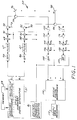
- FIG. 1 is a simplified schematic block diagram of a phased array antenna system employing the present invention to produce multiple independent transmit beams by digital beamforming techniques.
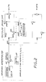
- FIG. 2 is a block diagram illustrative of one technique for applying the beamsteering coefficients to the waveform time samples.
- a phased array antenna system 50 employing the invention is shown in FIG. 1.
- the system 50 comprises a subarray signal generator 51, which in turn includes a waveform generator 52 which generates a video signal representing a desired waveform to be transmitted.
- the waveform is synthesized digitally, and in-phase (I) and quadrature (Q) samples of the waveform are fed to the multiplier device 54 comprising the subarray signal generator 51.
- the synthesis of the waveform can be done by generator 52 in one of several ways. For example, if the waveform is repetitive, as in a radar application, samples (time series) of the radar pulse could be stored in read-only-memory (ROM) 53. To synthesize both phase and amplitude, in-phase and quadrature components of the baseband signal waveform are generated.
- ROM read-only-memory
- the I and Q samples from the waveform modulator of the waveform generator 52 which are represented as ⁇ (t i )e k ⁇ (t i ) , are the baseband representation of the radar transmitted waveform.
- Equation (1) The mathematical operation described in equation (1) is performed in the waveform generator 52 by the complex number multiplier (60) and digital local oscillator (LO) 64 shown in FIG. 2. By performing this mixing operation, the waveform is converted from its baseband I and Q representation to its complex number Intermediate Frequency representation.
- the antenna aperture is divided into M subarrays.
- Each subarray may consist of single or multiple antenna elements.
- the subarray radiation pattern may be steered using conventional microwave (analog) beamforming techniques.
- amplitude taper within the subarray aperture may be employed to reduce the sidelobes of the subarray radiation pattern. Reduction of sidelobes together with physical overlap of the subarrays can be used to mitigate the effects of grating lobes that can occur when forming multiple beams from a subarrayed antenna.
- the transmit beamforming coefficients may also be stored in the memory 53, and are applied to the signal samples from the waveform generator 52 of the subarray signal generator shown in FIG. 2 by the multiplier device 54 to produce the transmit antenna beams.
- the amplitude and phase distribution for each beam is determined by the desired beam position (angle) and sidelobe distribution.
- the algebraic summation of the respective phasors for each beam is formed, and the time samples from the waveform generator 52 are multiplied by the algebraic sum.
- two beams are to be formed, with the amplitude and phase distribution of the first beam defined by the phasor A i exp(j ⁇ i ) and the amplitude and phase distribution of the second beam defined by the phasor B i exp(j ⁇ i ).
- the input sample to the ith subarray at the kth time instant is determined as shown in eq. 3.
- the multiplier device 54 for the exemplary ith subarray channel multiplies the real and imaginary components of the complex waveform y i (k) by the respective real and imaginary components of the algebraic sum (represented as C i ) as described in equation 3.
- the products from multipliers 54B and 54C are then summed at summer 54A to form the resulting signal waveform y i (k).
- the sum signal is converted to analog form by digital-to-analog converter (DAC) 66.
- DAC digital-to-analog converter
- the resulting analog signal is mixed up to the RF transmit frequency by mixers 68 and 70 and local oscillator signals LO1 and LO2 generated by reference signal generator 81.
- the RF signal is amplified by the transmit power amplifier 72, and transmitted out of the subarray via circulator 74 and the subarray radiating element(s) 76.
- the LO1 frequency may typically be in the range of 10-30 MHz, and the LO2 frequency may typically be at L band (1-3 GHz).
- L band 1-3 GHz.
- the use of the L01 signal is not mandatory but simplifies the filtering of unwanted image sidebands created during the mixing process by filters 67 and 87.
- the I and Q coefficients for the Mth subarray are multiplied with the LO 64 signal by multipliers 80 and 82 to mix from baseband to the low IF frequency.
- the digital samples are then converted to analog form by DAC 86, mixed up the transmit RF frequency by mixers 88 and 90 and LO1 and LO2, amplified by amplifier 92, and then transmitted out of the Mth subarray via the circulator 94 and the radiating element(s) 78.
- the system 50 of FIG. 1 employs "IF" sampling techniques to allow conversion with a single DAC for each subarray. Moreover, the phase and amplitude distribution for each beam could alternatively be generated by imposing the appropriate amplitude and phase on the digital LO 64, rather than on the signal samples themselves by the multiplier device 54; in some applications, this approach would reduce computation requirements.
- the system 50 further comprises receive elements for each subarray. For clarity only the elements for the first and Mth subarray are shown in FIG. 1.
- the first subarray radiating element(s) 76 is coupled through circulator 74 to protector circuit 100, and the signal is amplified by low noise amplifier 102.
- the protector circuit 100 prevents a large signal from damaging the low noise amplifier 102; a typical protector circuit is a diode limiter protector.
- the amplified receive signal is downconverted by mixing with LO1 and LO2 at mixer devices 104 and 106, converted to digital form by analog to digital converter (ADC) 108, and the digitized signal is fed to the receive digital beamformer 110 to form the desired receive beams.
- ADC analog to digital converter
- the signals received at the Mth subarray are fed through a protector device 114 and amplified by amplifier 116, downconverted by mixing with LO1 and LO2 at mixers 118 and 120, and converted to digital form at ADC 124.
- the digital signals are processed by the receive digital beamformer 110 and the processor 112.
- fiber optic signal transmission technology can be advantageously employed to transmit signals, on the transmit side, between the multiplier device 54 and the respective transmit power amplifiers 72 and 92, and on the receive side, between the low noise amplifiers 102 and 116 and the receive digital beamformer 110.
- An exemplary fiber optic feed network is described in U.S. Patent 4,814,773.
- a digital transmit beamformer for phased array systems has been disclosed which provides several advantages. For example, with digital beamforming the phase angles are digitally controlled, and enough digital bits can be used to establish each phase angle very precisely.
- analog phase shifters have a relatively small number of discrete phase settings, and are subject to further phase errors due to manufacturing and temperature tolerances. The resulting phase errors degrade the beam and lead to increased sidelobe levels. Therefore, digital beam formation in accordance with the invention results in very significant reductions in phase errors. As a result, the invention provides more accurate beamforming and positioning with improved sidelobe control. Precise control of the phase angle also permits ready formation of custom beams (as in conformal arrays).
- digital transmit beamforming is non-dispersive, unlike conventional microwave techniques, and is applicable at all RF frequencies.
- the invention is particularly well suited to very high RF frequencies (e.g., millimeter wave frequencies at 60-70 GHz) for which analog phase shifters are difficult to construct.
- digital transmit beamforming in accordance with the invention is applicable for synthesizing time-delays for broadband beam forming, in which the time of successive radiators is delayed to obtain both phase and time coherency in the radiated wavefront at an angle from broadside.
Landscapes
- Radar Systems Or Details Thereof (AREA)
- Variable-Direction Aerials And Aerial Arrays (AREA)
Description
- The present invention relates to a phased array system according to the preamble of claim 1, and more particularly to a method for digital formation of multiple independent beams on transmission.
- It is well known that phased antenna arrays can be configured to provide the capability of transmitting multiple independent beams. See, e.g., "Introduction to Radar Systems," Merrill I. Skolnick, McGraw-Hill Book Company, second edition, 1980, pages 310-318. The typical techniques for producing multiple independent transmit beams include complex feed networks with multiple phase shifters (one set for each beam) , complex lenses or complex hybrid phasing matrices. These techniques can all be shown to have relative weight, size, performance and cost disadvantages, particularly for space and airborne radar application. A system according to the preamble of claim 1 is known from "wissenschaftliche Berichte AEG-Telefunken", vol.54, n°. 1/2 . 1981, pages 25-43.
- Techniques have been described in the literature for generating multiple beams on receive by digital beamforming techniques. "Digital Multiple Beamforming Techniques for Radar," Abraham E. Ruvin and Leonard Weinberg, IEEE EASCON ′78 Record, pages 152-163, Sept. 25-27, 1978, IEEE Publication 78 CH 1354-4 AES. No description appears in this reference of forming independent multiple transmit beams by digital beamforming techniques.
- It is therefore an object of the present invention to provide a phased antenna array system having the capability of generating multiple independent beams without the use of multiple sets of phase shifters, complex lenses or hybrid phasing matrices.
- A further object of the present invention is to provide a phased antenna array system having the capability of generating multiple independent transmit beams by digital beamforming techniques.
- This object is solved by the advantageous measures indicated in the characterising portion of claim 1 and 7, respectively.
- The features and advantages of the present invention will become more apparent from the following detailed description of an exemplary embodiment thereof, as illustrated in the accompanying drawings, in which:
- FIG. 1 is a simplified schematic block diagram of a phased array antenna system employing the present invention to produce multiple independent transmit beams by digital beamforming techniques.
- FIG. 2 is a block diagram illustrative of one technique for applying the beamsteering coefficients to the waveform time samples.
- A phased
array antenna system 50 employing the invention is shown in FIG. 1. Thesystem 50 comprises a subarray signal generator 51, which in turn includes awaveform generator 52 which generates a video signal representing a desired waveform to be transmitted. The waveform is synthesized digitally, and in-phase (I) and quadrature (Q) samples of the waveform are fed to themultiplier device 54 comprising the subarray signal generator 51. - The synthesis of the waveform can be done by
generator 52 in one of several ways. For example, if the waveform is repetitive, as in a radar application, samples (time series) of the radar pulse could be stored in read-only-memory (ROM) 53. To synthesize both phase and amplitude, in-phase and quadrature components of the baseband signal waveform are generated. - The I and Q samples from the waveform modulator of the
waveform generator 52, which are represented as α(ti)ekφ(ti ), are the baseband representation of the radar transmitted waveform. By representing each sample by the complex number I+jQ, the center frequency can be shifted from baseband to a different center frequency fo by
where
tk = time at the kth sample instant
wo = 2πfo - The mathematical operation described in equation (1) is performed in the
waveform generator 52 by the complex number multiplier (60) and digital local oscillator (LO) 64 shown in FIG. 2. By performing this mixing operation, the waveform is converted from its baseband I and Q representation to its complex number Intermediate Frequency representation. - In FIG. 1, the antenna aperture is divided into M subarrays. Each subarray may consist of single or multiple antenna elements. In the latter case, the subarray radiation pattern may be steered using conventional microwave (analog) beamforming techniques. In addition, amplitude taper within the subarray aperture may be employed to reduce the sidelobes of the subarray radiation pattern. Reduction of sidelobes together with physical overlap of the subarrays can be used to mitigate the effects of grating lobes that can occur when forming multiple beams from a subarrayed antenna.
- The transmit beamforming coefficients may also be stored in the
memory 53, and are applied to the signal samples from thewaveform generator 52 of the subarray signal generator shown in FIG. 2 by themultiplier device 54 to produce the transmit antenna beams. The amplitude and phase distribution for each beam is determined by the desired beam position (angle) and sidelobe distribution. Mathematically, to generate a single beam, thedevice 54 multiplies each time sample from thewaveform generator 52 by a phasor Aiexp(jφi) as follows: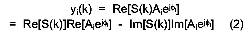
where S(k) = synthesized waveform (I + jQ) at the kth time sample, Ai = amplitude taper at the ith subarray, φi = phase shift at the ith subarray, and yi(k) = input sample to the ith subarray at the kth time instant. - In order to generate multiple beams, the algebraic summation of the respective phasors for each beam is formed, and the time samples from the
waveform generator 52 are multiplied by the algebraic sum. Here, two beams are to be formed, with the amplitude and phase distribution of the first beam defined by the phasor Aiexp(jφi) and the amplitude and phase distribution of the second beam defined by the phasor Biexp(jϑi). In this case, the input sample to the ith subarray at the kth time instant is determined as shown in eq. 3.
where
and Bi = amplitude taper of the second beam at the ith subarray, ϑi = phase shift of the second beam at the ith subarray. Obviously the number of beams formed in this manner can be extended to any number. - As illustrated in FIG. 2, the
multiplier device 54 for the exemplary ith subarray channel multiplies the real and imaginary components of the complex waveform yi(k) by the respective real and imaginary components of the algebraic sum (represented as Ci) as described in equation 3. The products from multipliers 54B and 54C are then summed at summer 54A to form the resulting signal waveform yi(k). - After the I and Q samples of the multiplier output are summed by summer 54A, the sum signal is converted to analog form by digital-to-analog converter (DAC) 66. The resulting analog signal is mixed up to the RF transmit frequency by
mixers reference signal generator 81. The RF signal is amplified by thetransmit power amplifier 72, and transmitted out of the subarray via circulator 74 and the subarray radiating element(s) 76. - Two upconverting local oscillators are employed to reduce the required speed of operation of the
DAC 66. For example, the LO1 frequency may typically be in the range of 10-30 MHz, and the LO2 frequency may typically be at L band (1-3 GHz). The use of the L01 signal is not mandatory but simplifies the filtering of unwanted image sidebands created during the mixing process byfilters - In a similar fashion, the I and Q coefficients for the Mth subarray are multiplied with the
LO 64 signal by multipliers 80 and 82 to mix from baseband to the low IF frequency. The digital samples are then converted to analog form byDAC 86, mixed up the transmit RF frequency bymixers amplifier 92, and then transmitted out of the Mth subarray via the circulator 94 and the radiating element(s) 78. - The
system 50 of FIG. 1 employs "IF" sampling techniques to allow conversion with a single DAC for each subarray. Moreover, the phase and amplitude distribution for each beam could alternatively be generated by imposing the appropriate amplitude and phase on thedigital LO 64, rather than on the signal samples themselves by themultiplier device 54; in some applications, this approach would reduce computation requirements. - The
system 50 further comprises receive elements for each subarray. For clarity only the elements for the first and Mth subarray are shown in FIG. 1. Thus, the first subarray radiating element(s) 76 is coupled through circulator 74 toprotector circuit 100, and the signal is amplified bylow noise amplifier 102. Theprotector circuit 100 prevents a large signal from damaging thelow noise amplifier 102; a typical protector circuit is a diode limiter protector. The amplified receive signal is downconverted by mixing with LO1 and LO2 atmixer devices - In a similar fashion the signals received at the Mth subarray are fed through a
protector device 114 and amplified byamplifier 116, downconverted by mixing with LO1 and LO2 atmixers - It is contemplated that fiber optic signal transmission technology can be advantageously employed to transmit signals, on the transmit side, between the
multiplier device 54 and the respective transmitpower amplifiers low noise amplifiers - A digital transmit beamformer for phased array systems has been disclosed which provides several advantages. For example, with digital beamforming the phase angles are digitally controlled, and enough digital bits can be used to establish each phase angle very precisely. In contrast, analog phase shifters have a relatively small number of discrete phase settings, and are subject to further phase errors due to manufacturing and temperature tolerances. The resulting phase errors degrade the beam and lead to increased sidelobe levels. Therefore, digital beam formation in accordance with the invention results in very significant reductions in phase errors. As a result, the invention provides more accurate beamforming and positioning with improved sidelobe control. Precise control of the phase angle also permits ready formation of custom beams (as in conformal arrays). Additional advantages include the fact that digital transmit beamforming is non-dispersive, unlike conventional microwave techniques, and is applicable at all RF frequencies. In fact the invention is particularly well suited to very high RF frequencies (e.g., millimeter wave frequencies at 60-70 GHz) for which analog phase shifters are difficult to construct. A further advantage is that digital transmit beamforming in accordance with the invention is applicable for synthesizing time-delays for broadband beam forming, in which the time of successive radiators is delayed to obtain both phase and time coherency in the radiated wavefront at an angle from broadside.
- It is apparent that different frequencies may be used for the different beams. One technique for achieving this result is to use different local oscillator frequencies on transmit at the respective
local oscillators 64. Of course, correspondingly by different local oscillator frequencies will be used on receive.
Claims (12)
- A phased array system with an antenna aperture divided into a plurality of subarrays (76, 78), said array system having means (72, 92) for amplifying RF signals for each subarray and means (74, 94) for feeding said amplified RF signals to the appropriate subarrays for their transmission;
characterised in that said array system employs digital beamforming of multiple independent transmit beams and comprises:[a] means (52) for generating in-phase (I) and quadrature (Q) sequential digital samples of a desired signal waveform to be transmitted;[b] means (60, 64) for upconverting said I and Q sequential digital samples to intermediate frequency (IF) I and Q samples;[c] means (53) for providing, for each transmit beam to be formed, a different set of beamsteering phasors in digital form, each phasor representing the amplitude and phase distribution for the particular desired beam position and sidelobe distribution;[d] means (54) for applying the respective sets of beamsteering phasors to said IF I and Q samples to provide resulting IF I and Q coefficients for each subarray;[e] means (66, 86) for converting said IF I and Q coefficients for each subarray to an analogue IF signal;[f] and means (68, 70, 88, 90) for upconverting said analogue IF signal for each subarray to said RF signal having the desired RF transmit frequency. - Phased array system according to Claim 1, characterised in that said means [d] for applying said beamsteering phasors comprises means (54A) for forming the algebraic sum of said phasors and means (54B, 54C) for multiplying the sequential digital samples of the signal waveform by said algebraic sum.
- Phased array system according to Claims 1 or 2 characterised in that said means [a] for generating said digital samples comprises means for reading predetermined digital samples from a digital memory (53).
- Phased array system according to Claims 1, 2 or 3, characterised in that said means [b] for upconverting said I and Q samples to IF I and Q samples comprises a digital local oscillator (64) for generating a digital local oscillator signal and means (60) for multiplying the respective I and Q samples by said digital local oscillator signal.
- Phased array system according to any preceding claim, characterised in that said means [e] for converting said IF I and Q coefficients for each subarray to an analogue IF signal comprises a digital-to-analog converter (66, 86) for converting said IF I and Q coefficients.
- Phased array system according to any preceding claim, characterised in that said means [f] for upconverting said analogue IF signal to said RF signal comprises means (68, 88) for mixing said analogue IF signal with a first local oscillator signal to upconvert said analogue IF signal to a first RF frequency and means (70, 90) for mixing said up-converted signal at the first RF frequency with a second local oscillator signal to upconvert it to the desired RF frequency.
- A method of digital beamforming of multiple independent transmit beams in a phased array system with an antenna aperture divided into a plurality of subarrays (76, 78), said array system having means (72, 92) for amplifying RF signals for each subarray and means (74, 94) for feeding said amplified RF signals to the appropriate subarrays for their transmission;
characterised by the steps of:[a] generating in-phase (I) and quadrature (Q) sequential digital samples of a desired signal waveform to be transmitted;[b] upconverting said I and Q sequential digital samples to intermediate frequency (IF) I and Q samples;[c] providing, for each transmit beam to be formed, a different set of beamsteering phasors in digital form, each phasor representing the amplitude and phase distribution for the particular desired beam position and sidelobe distribution;[d] applying the respective sets of beamsteering phasors to said IF I and Q samples to provide resulting IF I and Q coefficients for each subarray;[e] converting said IF I and Q coefficients for each subarray to an analogue IF signal;[f] upconverting said analogue IF signal for each subarray to said RF signal having the desired RF transmit frequency;[g] and applying said RF signal to said means (72, 92) for amplifying. - Method according to claim 7, characterised in that said step [d] comprises the steps of forming the algebraic sum of said phasors and of multiplying the sequential digital samples of the signal waveform by said algebraic sum.
- Method according to claims 7 or 8, characterised in that said step [a] comprises the step of reading predetermined digital signals from a digital memory (53).
- Method according to one of claims 7 through 9, characterised in that said step [b] comprises the step of multiplying the I and Q coefficients by a digital local oscillator signal.
- Method according to one of claims 7 through 10, characterised in that said step [e] comprises the step of of converting said IF I and Q coefficients by means of a digital-to-analog converter (66, 86).
- Method according to one of claims 7 through 11, characterised in that said step [f] comprises the step of of mixing said analogue IF signal with a first local oscillator signal to upconvert it to a first RF frequency and of mixing said upconverted signal at the first RF frequency with a second local oscillator signal to upconvert it to the desired RF frequency.
Applications Claiming Priority (2)
| Application Number | Priority Date | Filing Date | Title |
|---|---|---|---|
| US422934 | 1989-10-17 | ||
| US07/422,934 US4965602A (en) | 1989-10-17 | 1989-10-17 | Digital beamforming for multiple independent transmit beams |
Publications (3)
| Publication Number | Publication Date |
|---|---|
| EP0423552A2 EP0423552A2 (en) | 1991-04-24 |
| EP0423552A3 EP0423552A3 (en) | 1991-09-11 |
| EP0423552B1 true EP0423552B1 (en) | 1995-11-22 |
Family
ID=23677013
Family Applications (1)
| Application Number | Title | Priority Date | Filing Date |
|---|---|---|---|
| EP90119043A Revoked EP0423552B1 (en) | 1989-10-17 | 1990-10-04 | Digital beamforming for multiple independent transmit beams |
Country Status (4)
| Country | Link |
|---|---|
| US (1) | US4965602A (en) |
| EP (1) | EP0423552B1 (en) |
| DE (1) | DE69023737T2 (en) |
| IL (1) | IL95815A (en) |
Cited By (1)
| Publication number | Priority date | Publication date | Assignee | Title |
|---|---|---|---|---|
| RU2507646C1 (en) * | 2012-06-18 | 2014-02-20 | Федеральное государственное унитарное предприятие "Ростовский-на-Дону научно-исследовательский институт радиосвязи" (ФГУП "РНИИРС") | Method of nulling beam patterns of phased antenna arrays in directions of interference sources |
Families Citing this family (50)
| Publication number | Priority date | Publication date | Assignee | Title |
|---|---|---|---|---|
| FR2651609B1 (en) * | 1989-09-01 | 1992-01-03 | Thomson Csf | POINT CONTROL FOR AN ELECTRONIC SCANNING ANTENNA SYSTEM AND BEAM FORMATION THROUGH THE CALCULATION. |
| FR2690009B1 (en) * | 1992-04-14 | 1994-05-27 | Thomson Csf | LINEAR ANTENNA WITH CONSTANT DIRECTIVITY AND TRACK FORMING DEVICE FOR SUCH ANTENNA. |
| GB2267783B (en) * | 1992-06-09 | 1996-08-28 | British Aerospace | Beam forming |
| BR9507801A (en) * | 1994-06-03 | 1998-05-26 | Ericsson Telefon Ab L M | Process and system for calibrating the transmission and reception of an antenna array for use in a mobile radio communications system |
| US5675554A (en) * | 1994-08-05 | 1997-10-07 | Acuson Corporation | Method and apparatus for transmit beamformer |
| DE19581718T5 (en) * | 1994-08-05 | 2013-11-07 | Siemens Medical Solutions USA, Inc. (n.d. Ges. d. Staates Delaware) | Method and apparatus for transmit beamformer system |
| US5909460A (en) | 1995-12-07 | 1999-06-01 | Ericsson, Inc. | Efficient apparatus for simultaneous modulation and digital beamforming for an antenna array |
| US5856804A (en) * | 1996-10-30 | 1999-01-05 | Motorola, Inc. | Method and intelligent digital beam forming system with improved signal quality communications |
| US5754138A (en) * | 1996-10-30 | 1998-05-19 | Motorola, Inc. | Method and intelligent digital beam forming system for interference mitigation |
| US5754139A (en) * | 1996-10-30 | 1998-05-19 | Motorola, Inc. | Method and intelligent digital beam forming system responsive to traffic demand |
| RU2123743C1 (en) * | 1998-01-05 | 1998-12-20 | Мануилов Борис Дмитриевич | Method for setting zero of beam pattern of phased antenna array |
| US6246369B1 (en) * | 1999-09-14 | 2001-06-12 | Navsys Corporation | Miniature phased array antenna system |
| AU1441001A (en) * | 1999-10-28 | 2001-05-08 | Qualcomm Incorporated | Non stationary sectorized antenna |
| FR2821164B1 (en) * | 2001-02-16 | 2003-05-16 | Thomson Csf | DISTRIBUTED TRANSMISSION AND RECEPTION SYSTEM, PARTICULARLY RADAR WITH SYNTHETIC TRANSMISSION AND BEAM FORMATION BY CALCULATION |
| RU2195054C2 (en) * | 2001-02-21 | 2002-12-20 | Мануилов Борис Дмитриевич | Method for separate zero generation in sum and difference directivity patterns of single-pulse phased antenna array |
| WO2003041218A1 (en) * | 2001-11-09 | 2003-05-15 | Ems Technologies, Inc. | Beamformer for multi-beam broadcast antenna |
| US6778137B2 (en) * | 2002-03-26 | 2004-08-17 | Raytheon Company | Efficient wideband waveform generation and signal processing design for an active multi-beam ESA digital radar system |
| US7103383B2 (en) * | 2002-12-31 | 2006-09-05 | Wirless Highways, Inc. | Apparatus, system, method and computer program product for digital beamforming in the intermediate frequency domain |
| BR0318579A (en) * | 2003-10-30 | 2006-10-10 | Telecom Italia Mobile Spa | Method and system for performing digital beam forming on the radiating pattern of an array antenna, base transceiver station in a mobile communication network, and computer program product |
| RU2291459C2 (en) * | 2005-02-03 | 2007-01-10 | Федеральное Государственное Унитарное Предприятие "Нижегородский Научно-Исследовательский Институт Радиотехники" | System of protection of impulse radar stations from active noise interference |
| US8289199B2 (en) * | 2005-03-24 | 2012-10-16 | Agilent Technologies, Inc. | System and method for pattern design in microwave programmable arrays |
| US8587492B2 (en) * | 2009-04-13 | 2013-11-19 | Viasat, Inc. | Dual-polarized multi-band, full duplex, interleaved waveguide antenna aperture |
| US10516219B2 (en) | 2009-04-13 | 2019-12-24 | Viasat, Inc. | Multi-beam active phased array architecture with independent polarization control |
| US8693970B2 (en) | 2009-04-13 | 2014-04-08 | Viasat, Inc. | Multi-beam active phased array architecture with independant polarization control |
| US8289209B2 (en) * | 2009-04-13 | 2012-10-16 | Viasat, Inc. | Active butler and blass matrices |
| TWI520439B (en) | 2009-04-13 | 2016-02-01 | 凡爾賽特公司 | Half-duplex phased array antenna system |
| US9077427B2 (en) | 2009-07-30 | 2015-07-07 | Spatial Digital Systems, Inc. | Coherent power combining via wavefront multiplexing on deep space spacecraft |
| US8111646B1 (en) | 2009-07-30 | 2012-02-07 | Chang Donald C D | Communication system for dynamically combining power from a plurality of propagation channels in order to improve power levels of transmitted signals without affecting receiver and propagation segments |
| US10149298B2 (en) | 2009-07-30 | 2018-12-04 | Spatial Digital Systems, Inc. | Dynamic power allocations for direct broadcasting satellite (DBS) channels via wavefront multiplexing |
| RU2471271C2 (en) * | 2011-03-11 | 2012-12-27 | Петр Николаевич Башлы | Method of optimising wideband antenna arrays |
| US8737531B2 (en) | 2011-11-29 | 2014-05-27 | Viasat, Inc. | Vector generator using octant symmetry |
| US8699626B2 (en) | 2011-11-29 | 2014-04-15 | Viasat, Inc. | General purpose hybrid |
| US9275690B2 (en) | 2012-05-30 | 2016-03-01 | Tahoe Rf Semiconductor, Inc. | Power management in an electronic system through reducing energy usage of a battery and/or controlling an output power of an amplifier thereof |
| US9509351B2 (en) | 2012-07-27 | 2016-11-29 | Tahoe Rf Semiconductor, Inc. | Simultaneous accommodation of a low power signal and an interfering signal in a radio frequency (RF) receiver |
| US9780449B2 (en) | 2013-03-15 | 2017-10-03 | Integrated Device Technology, Inc. | Phase shift based improved reference input frequency signal injection into a coupled voltage controlled oscillator (VCO) array during local oscillator (LO) signal generation to reduce a phase-steering requirement during beamforming |
| US9184498B2 (en) | 2013-03-15 | 2015-11-10 | Gigoptix, Inc. | Extending beamforming capability of a coupled voltage controlled oscillator (VCO) array during local oscillator (LO) signal generation through fine control of a tunable frequency of a tank circuit of a VCO thereof |
| US9531070B2 (en) | 2013-03-15 | 2016-12-27 | Christopher T. Schiller | Extending beamforming capability of a coupled voltage controlled oscillator (VCO) array during local oscillator (LO) signal generation through accommodating differential coupling between VCOs thereof |
| US9722310B2 (en) | 2013-03-15 | 2017-08-01 | Gigpeak, Inc. | Extending beamforming capability of a coupled voltage controlled oscillator (VCO) array during local oscillator (LO) signal generation through frequency multiplication |
| US9837714B2 (en) | 2013-03-15 | 2017-12-05 | Integrated Device Technology, Inc. | Extending beamforming capability of a coupled voltage controlled oscillator (VCO) array during local oscillator (LO) signal generation through a circular configuration thereof |
| US9716315B2 (en) | 2013-03-15 | 2017-07-25 | Gigpeak, Inc. | Automatic high-resolution adaptive beam-steering |
| US9666942B2 (en) | 2013-03-15 | 2017-05-30 | Gigpeak, Inc. | Adaptive transmit array for beam-steering |
| US9906288B2 (en) | 2016-01-29 | 2018-02-27 | The Trustees Of Columbia University In The City Of New York | Circuits and methods for spatio-spectral interference mitigation |
| US10200081B2 (en) | 2016-02-12 | 2019-02-05 | The United States Of America, As Represented By The Secretary Of The Navy | Systems and methods for signal detection and digital bandwidth reduction in digital phased arrays |
| US9831933B1 (en) | 2016-08-10 | 2017-11-28 | The United States Of America As Represented By Secretary Of The Navy | Techniques and methods for frequency division multiplexed digital beamforming |
| US10374675B1 (en) * | 2018-03-06 | 2019-08-06 | Raytheon Company | Direct digital synthesis based phase shift digital beam forming |
| WO2020205650A1 (en) | 2019-03-30 | 2020-10-08 | AeroCharge Inc. | Methods and apparatus for wireless power transmission and reception |
| CA3209399A1 (en) * | 2021-02-24 | 2022-09-01 | Michael Thomas Pace | System and method for a digitally beamformed phased array feed |
| US12523756B1 (en) | 2021-03-03 | 2026-01-13 | Telephonics Corporation | Aesa true dual beam full range, full doppler spectrum imaging while scanning radar system |
| WO2023065005A1 (en) * | 2021-10-22 | 2023-04-27 | Huawei Technologies Canada Co., Ltd. | Methods and systems to produce fully-connected optical beamforming |
| US20250067844A1 (en) * | 2023-08-21 | 2025-02-27 | Rockwell Collins, Inc. | Sub-elemental phase center control for high-resolution rf scene projection |
Family Cites Families (3)
| Publication number | Priority date | Publication date | Assignee | Title |
|---|---|---|---|---|
| US4277787A (en) * | 1979-12-20 | 1981-07-07 | General Electric Company | Charge transfer device phased array beamsteering and multibeam beamformer |
| GB2130798B (en) * | 1982-10-06 | 1986-02-12 | Standard Telephones Cables Ltd | Digital beam-forming radar |
| US4922257A (en) * | 1987-01-27 | 1990-05-01 | Mitsubishi Denki Kabushiki Kaisha | Conformal array antenna |
-
1989
- 1989-10-17 US US07/422,934 patent/US4965602A/en not_active Expired - Lifetime
-
1990
- 1990-09-26 IL IL9581590A patent/IL95815A/en not_active IP Right Cessation
- 1990-10-04 EP EP90119043A patent/EP0423552B1/en not_active Revoked
- 1990-10-04 DE DE69023737T patent/DE69023737T2/en not_active Revoked
Cited By (1)
| Publication number | Priority date | Publication date | Assignee | Title |
|---|---|---|---|---|
| RU2507646C1 (en) * | 2012-06-18 | 2014-02-20 | Федеральное государственное унитарное предприятие "Ростовский-на-Дону научно-исследовательский институт радиосвязи" (ФГУП "РНИИРС") | Method of nulling beam patterns of phased antenna arrays in directions of interference sources |
Also Published As
| Publication number | Publication date |
|---|---|
| DE69023737D1 (en) | 1996-01-04 |
| IL95815A (en) | 1995-03-15 |
| EP0423552A2 (en) | 1991-04-24 |
| US4965602A (en) | 1990-10-23 |
| DE69023737T2 (en) | 1996-04-18 |
| EP0423552A3 (en) | 1991-09-11 |
Similar Documents
| Publication | Publication Date | Title |
|---|---|---|
| EP0423552B1 (en) | Digital beamforming for multiple independent transmit beams | |
| US5764187A (en) | Direct digital synthesizer driven phased array antenna | |
| US7319427B2 (en) | Frequency diverse array with independent modulation of frequency, amplitude, and phase | |
| US6529162B2 (en) | Phased array antenna system with virtual time delay beam steering | |
| US4277787A (en) | Charge transfer device phased array beamsteering and multibeam beamformer | |
| US7511665B2 (en) | Method and apparatus for a frequency diverse array | |
| Steyskal | Digital beamforming | |
| US6778137B2 (en) | Efficient wideband waveform generation and signal processing design for an active multi-beam ESA digital radar system | |
| Barton | Digital beam forming for radar | |
| US4720712A (en) | Adaptive beam forming apparatus | |
| US5787049A (en) | Acoustic wave imaging apparatus and method | |
| US4749995A (en) | Phased array radar antenna system | |
| US4160975A (en) | Correction circuit for wide bandwidth antenna | |
| US5475392A (en) | Frequency translation of true time delay signals | |
| Yu et al. | A hybrid radar system with a phased transmitting array and a digital beamforming receiving array | |
| WO2000074170A2 (en) | Mixed signal true time delay digital beamformer | |
| EP3521852B1 (en) | Radar beamforming method | |
| JPH07273530A (en) | Emission device array antenna | |
| EP2088640B1 (en) | Wideband array antenna | |
| US4146889A (en) | Method and apparatus for sidelobe reduction in radar | |
| US6307506B1 (en) | Method and apparatus for enhancing the directional transmission and reception of information | |
| CA1253959A (en) | Phased array antenna feed | |
| Ahn et al. | Digital beamforming in a large conformal phased array antenna for satellite TT&C | |
| Torres-Rosario | Implementation of a phased array antenna using digital beamforming | |
| JPH06242229A (en) | Radar equipment |
Legal Events
| Date | Code | Title | Description |
|---|---|---|---|
| PUAI | Public reference made under article 153(3) epc to a published international application that has entered the european phase |
Free format text: ORIGINAL CODE: 0009012 |
|
| AK | Designated contracting states |
Kind code of ref document: A2 Designated state(s): DE FR GB IT |
|
| PUAL | Search report despatched |
Free format text: ORIGINAL CODE: 0009013 |
|
| AK | Designated contracting states |
Kind code of ref document: A3 Designated state(s): DE FR GB IT |
|
| 17P | Request for examination filed |
Effective date: 19920228 |
|
| 17Q | First examination report despatched |
Effective date: 19931215 |
|
| GRAA | (expected) grant |
Free format text: ORIGINAL CODE: 0009210 |
|
| AK | Designated contracting states |
Kind code of ref document: B1 Designated state(s): DE FR GB IT |
|
| REF | Corresponds to: |
Ref document number: 69023737 Country of ref document: DE Date of ref document: 19960104 |
|
| ITF | It: translation for a ep patent filed | ||
| ET | Fr: translation filed | ||
| PLBQ | Unpublished change to opponent data |
Free format text: ORIGINAL CODE: EPIDOS OPPO |
|
| PLBI | Opposition filed |
Free format text: ORIGINAL CODE: 0009260 |
|
| PLBF | Reply of patent proprietor to notice(s) of opposition |
Free format text: ORIGINAL CODE: EPIDOS OBSO |
|
| 26 | Opposition filed |
Opponent name: EUROPEAN SPACE AGENCY Effective date: 19960814 |
|
| PLBF | Reply of patent proprietor to notice(s) of opposition |
Free format text: ORIGINAL CODE: EPIDOS OBSO |
|
| PLBF | Reply of patent proprietor to notice(s) of opposition |
Free format text: ORIGINAL CODE: EPIDOS OBSO |
|
| PLBF | Reply of patent proprietor to notice(s) of opposition |
Free format text: ORIGINAL CODE: EPIDOS OBSO |
|
| PGFP | Annual fee paid to national office [announced via postgrant information from national office to epo] |
Ref country code: FR Payment date: 19970910 Year of fee payment: 8 |
|
| PGFP | Annual fee paid to national office [announced via postgrant information from national office to epo] |
Ref country code: GB Payment date: 19970918 Year of fee payment: 8 |
|
| PGFP | Annual fee paid to national office [announced via postgrant information from national office to epo] |
Ref country code: DE Payment date: 19970922 Year of fee payment: 8 |
|
| RDAH | Patent revoked |
Free format text: ORIGINAL CODE: EPIDOS REVO |
|
| RDAG | Patent revoked |
Free format text: ORIGINAL CODE: 0009271 |
|
| STAA | Information on the status of an ep patent application or granted ep patent |
Free format text: STATUS: PATENT REVOKED |
|
| REG | Reference to a national code |
Ref country code: GB Ref legal event code: 732E |
|
| 27W | Patent revoked |
Effective date: 19980425 |
|
| GBPR | Gb: patent revoked under art. 102 of the ep convention designating the uk as contracting state |
Free format text: 980425 |