EP0423372A1 - Driving control device for vehicle and control method therefor - Google Patents
Driving control device for vehicle and control method therefor Download PDFInfo
- Publication number
- EP0423372A1 EP0423372A1 EP90907382A EP90907382A EP0423372A1 EP 0423372 A1 EP0423372 A1 EP 0423372A1 EP 90907382 A EP90907382 A EP 90907382A EP 90907382 A EP90907382 A EP 90907382A EP 0423372 A1 EP0423372 A1 EP 0423372A1
- Authority
- EP
- European Patent Office
- Prior art keywords
- travel
- angle
- lever
- controller
- upper rotary
- Prior art date
- Legal status (The legal status is an assumption and is not a legal conclusion. Google has not performed a legal analysis and makes no representation as to the accuracy of the status listed.)
- Withdrawn
Links
Images


Classifications
-
- E—FIXED CONSTRUCTIONS
- E02—HYDRAULIC ENGINEERING; FOUNDATIONS; SOIL SHIFTING
- E02F—DREDGING; SOIL-SHIFTING
- E02F9/00—Component parts of dredgers or soil-shifting machines, not restricted to one of the kinds covered by groups E02F3/00 - E02F7/00
- E02F9/20—Drives; Control devices
- E02F9/22—Hydraulic or pneumatic drives
-
- E—FIXED CONSTRUCTIONS
- E02—HYDRAULIC ENGINEERING; FOUNDATIONS; SOIL SHIFTING
- E02F—DREDGING; SOIL-SHIFTING
- E02F9/00—Component parts of dredgers or soil-shifting machines, not restricted to one of the kinds covered by groups E02F3/00 - E02F7/00
- E02F9/20—Drives; Control devices
- E02F9/2025—Particular purposes of control systems not otherwise provided for
- E02F9/2045—Guiding machines along a predetermined path
-
- E—FIXED CONSTRUCTIONS
- E02—HYDRAULIC ENGINEERING; FOUNDATIONS; SOIL SHIFTING
- E02F—DREDGING; SOIL-SHIFTING
- E02F9/00—Component parts of dredgers or soil-shifting machines, not restricted to one of the kinds covered by groups E02F3/00 - E02F7/00
- E02F9/20—Drives; Control devices
- E02F9/2004—Control mechanisms, e.g. control levers
-
- E—FIXED CONSTRUCTIONS
- E02—HYDRAULIC ENGINEERING; FOUNDATIONS; SOIL SHIFTING
- E02F—DREDGING; SOIL-SHIFTING
- E02F9/00—Component parts of dredgers or soil-shifting machines, not restricted to one of the kinds covered by groups E02F3/00 - E02F7/00
- E02F9/20—Drives; Control devices
- E02F9/2025—Particular purposes of control systems not otherwise provided for
- E02F9/2037—Coordinating the movements of the implement and of the frame
-
- E—FIXED CONSTRUCTIONS
- E02—HYDRAULIC ENGINEERING; FOUNDATIONS; SOIL SHIFTING
- E02F—DREDGING; SOIL-SHIFTING
- E02F9/00—Component parts of dredgers or soil-shifting machines, not restricted to one of the kinds covered by groups E02F3/00 - E02F7/00
- E02F9/20—Drives; Control devices
- E02F9/22—Hydraulic or pneumatic drives
- E02F9/225—Control of steering, e.g. for hydraulic motors driving the vehicle tracks
Definitions
- This invention relates to a vehicle travel controller and a control method for the same and, more particularly, to a controller and a method for a controlling travel of an industrial vehicle, more specifically, a construction vehicle such as a hydraulic power shovel.
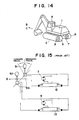
- a vehicle such as that shown in Fig. 14, comprising an upper rotary body 1 having a cab 4, and a lower traveling unit 2 made up of a right track 6 having a right travel motor 7 and a left track 8 having a left travel motor 9, a right travel lever 51 and a left travel lever 52 linked to pilot pressure generating valves 53 are provided in the cab 4, and a right travel operation valve 12 and a left travel operation valve 13 mounted on the upper rotary body 1 are respectively connected to the right and left pilot pressure generating valves 53, the right travel motor 7 and the right travel operation valve 12, and the left travel motor 9 and the left travel operation valve 13 attached to the lower traveling unit 2 being connected respectively, as shown in Fig. 15.
- Pressure oil is supplied from an unillustrated hydraulic pressure generation source to these circuits.
- the pilot pressure generating valve 53 When the right travel lever 51 is inclined toward the front of the upper rotary body 1 (in the direction B), i.e., in the forward traveling direction, the pilot pressure generating valve 53 generates a pilot pressure to operate the right travel operation valve 12 and to thereby rotate the right travel motor 7 in the forward traveling direction.
- the right track 6 moves forward and the lower traveling unit 2 and the upper rotary body integrally turn counterclockwise.
- the left travel lever 52 is inclined in the forward traveling direction, only the left track 8 moves forward and the vehicle turns clockwise.
- the right and left travel levers 51 and 52 are simultaneously inclined in the forward traveling direction, the vehicle moves straight ahead.
- the present invention has been achieved in view of the above-described problems, and an object of the present invention is to provide a vehicle travel controller and a control method for the same which enable the operator to easily make the vehicle travel in any direction selected.
- a vehicle travel controller in accordance with the present invention has a travel lever mounted on the upper rotary body and serving to control the traveling direction, a lever angle detector for detecting the angle of the direction of operation of the travel lever, a vehicle body rotation encoder for detecting the relative rotation angle between the upper rotary body and the lower traveling unit, a controller for effecting arithmetic operation of signals supplied from the lever angle detector and the vehicle body rotation encoder, and a travel operation valve capable of operating by receiving a signal output from the controller.
- a travel lever mounted on the upper rotary and serving to control the traveling direction and the traveling speed may be provided together with a lever angle detector for detecting the angle of the direction of operation of the travel lever and the angle of inclination of the same.
- a gyro compass provided on the upper rotary body to always indicate the geomagnetic north and to detect the angle between the upper rotary body and the north direction may also be provided.
- a vehicle travel control method in accordance with the present invention comprising inclining the travel lever in a desired traveling direction, detecting the angle of the direction of operation of the travel lever with the lever angle detector, detecting the relative rotation angle between the upper rotary body and the lower traveling unit with the vehicle body rotation encoder, supplying signals relating to these angles to the controller, effecting arithmetic operation with the controller to determine the direction of turning of the lower traveling unit, supplying a signal output therefrom to the travel operation valve to make the lower traveling unit perform non-traveling turning, stopping non-traveling turning when the lower traveling unit becomes parallel to the direction of travel lever operation, and controlling the travel operation valve to make the lower traveling unit travel straight in the direction of travel lever operation.
- the arrangement may be such that the angle of the direction of operation of the travel lever and the angle of inclination of the same are detected with the lever angle detector; signals relating to them are supplied to the controller; a signal output from the controller is supplied to the travel operation valve to make the lower traveling unit perform non-traveling turning at a speed proportional to the inclination angle of the travel lever; this non-traveling turning is stopped when the lower traveling unit becomes parallel to the direction of travel lever operation; and the travel operation valve is controlled to make the lower traveling unit travel straight in the direction of operation of the travel lever at a speed proportional to the inclination angle of the same.
- the arrangement may be such that the angle between the upper rotary body and the geomagnetic north is detected with a gyro compass; relating signals are supplied to the controller; a signal output from the controller is supplied to the travel operation valve to make the lower traveling unit perform non-traveling turning; the initial angle between the upper rotary body and the indicated north stored by the controller is compared with the corresponding angle during turning; a turning operation valve is controlled to turn the upper rotary body so that the initial angle is reached if the difference therebetween is larger than a predetermined angle; turning is stopped when the relative rotation angle between the direction of travel lever operation and the lower traveling unit is within a predetermined range and when the angle between the upper rotary body and the indicated north becomes within a predetermined range with respect to the corresponding initial angle; and the travel operation valve is controlled to make the lower traveling unit travel in the direction of travel lever operation.
- the operator can incline the travel lever in a direction in which the operator wishes to make the the vehicle travel, and can make the vehicle travel in this direction. Also, the operator can incline the travel lever in a selected traveling direction according to a desired speed to make the vehicle travel in the same direction at a speed proportional to the inclination angle. Further, the operator can easily make the vehicle travel in a selected direction without changing the intermediate attitude only by inclining one travel lever in the selected traveling direction, and there is no possibility of illusion with respect to the traveling direction, thus ensuring safe traveling.
- Figs. 1 to 6 are diagrams of a first embodiment of the present invention
- Fig. 1 is a diagram of the overall construction
- Fig. 2 is a diagram of the travel lever operating direction
- Figs. 3, 4, and 6 are diagrams of the relationship between the relative turning angle and the operating direction angle
- Fig. 5 is a flow chart of the arithmetic processing program.
- Figs. 7 to 9 are diagrams of a second embodiment of the present invention.
- Fig. 7 is a diagram of the overall construction;
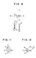
- Fig. 8 is a diagram of the travel lever operating direction and the inclination angle; and
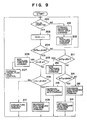
- Fig. 9 is a flow chart of the arithmetic processing program.
- Figs. 10 to 13 are diagrams of a third embodiment of the present invention.
- Fig. 10 is a diagram of the overall construction;
- Figs. 11 and 12 are diagrams of the relationship between the relative turning angle, the operating direction angle and the north direction angle; and
- Fig. 13 is a flow chart of the arithmetic processing program.
- Fig. 14 is a schematic diagram of the whole of a vehicle
- Fig. 15 is a diagram of the construction of a conventional travel controller
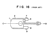
- Fig. 16 is a diagram of the direction in which the conventional vehicle travels.
- Fig. 1 shows the overall construction of the first embodiment.
- a vehicle body rotation encoder 3 is mounted on the center of rotation of an upper rotary body 1 rotatably and axially connected to a lower traveling unit 2 comprising a right track 6 having a right travel motor 7 and a left track 8 having a left travel motor 9, and one travel lever 10, such as that shown in Fig. 2, which has at its lower end a lever angle detector 5 and which is capable of being inclined in each of directions X, Y and an intermediate direction is provided in a cab 4 fixed on the upper rotary body 1.
- the vehicle body rotation encoder 3, the lever angle detector 5 and a controller 11 fixed on the upper rotary body 1 are connected by wiring.
- the controller 11 and pilot portions of a right travel operation valve 12 and a left travel operation valve 13 of an electromagnetic hydraulic pilot type provided in the upper rotary body 1 are connected by wiring.
- the right travel motor 7 and the right travel operation valve 12, and the left travel motor 9 and the left travel operation valve 13 are connected by pressure pipe lines, and pressure oil is supplied from an unillustrated hydraulic pressure generation source to these pipe lines.
- the center line of the upper rotary body 1 is indicated by BE and the forward direction thereof is indicated by B
- the center line of the lower traveling unit 2 is indicated by CD and the forward direction thereof is indicated by C
- the relative rotation angle between the upper rotary body 1 and the lower traveling unit 2 is represented by ⁇ .
- the angle between a straight line XX parallel to the center line BE of the upper rotary body 1 and passing through the center of the lever and the direction A in which the lever 10 is operated is represented by ⁇ .
- the angle ⁇ is positive when measured clockwise based on a segment CN in the direction C of the center line CD of the lower traveling unit 2, or it is negative, that is, expressed as - ⁇ when measured counterclockwise, and the angle ⁇ is positive when measured clockwise based on a segment BN, or it is negative, that is, expressed as - ⁇ when measured counterclockwise.
- the vehicle body rotation encoder 3 reads the relative angle ⁇ between the upper rotary body 1 and the lower traveling unit 2 and sends a signal to the controller 11, and the lever angle detector 5 reads the angle ⁇ of the direction in which the travel lever 10 is operated, and sends a signal to the controller 11.
- the controller 11 effects arithmetic operation of these signals, determines a turning direction in which the lower traveling unit 2 can be turned by a minimum angle to face in the direction in which the traveling lever 10 is operated, and sends signals to the travel operation valves 12 and 13 to make the lower traveling unit 2 effect a non-traveling turn.
- the direction C of the center line of the lower traveling unit 2 before turning is changed to a direction C', as shown in Fig. 4.
- the direction A in which the operation lever 10 is operated is correspondingly changed to a direction A', and the operator therefore returns the traveling lever 10 operating direction to the position A.
- This operation is continued until the angle ⁇ + ⁇ between the direction C and the direction A reaches a predetermined angle K.
- the controller 11 sends signals for stopping non-traveling turning and for starting forward or rearward traveling to the travel operation valves 12 and 13, thereby making the vehicle travel straight.
- step 100 If the travel lever 10 is not ON in step 100, commands are issued in steps 101 and 102 to stop forward/rearward traveling and non-traveling, so that the vehicle is stopped. If in step 100 the travel lever 10 is inclined in the selected traveling direction, the angles ⁇ and ⁇ are read in step 103, and examination is made in step 104 as to whether or not - 90° ⁇ ⁇ ⁇ + ⁇ ⁇ ⁇ 90° is established. If YES, examination is made in step 105 as to whether or not the absolute value of ⁇ + ⁇ is smaller than the predetermined angle K.
- a command is issued in step 110 to effect a leftward non-traveling turn by a minimum turning angle.
- the travel lever 10 is corrected as mentioned above, ⁇ and ⁇ are read, and the same operation is repeated until
- step 113 a rearward traveling direction command is issued to make the vehicle travel in the direction A because in this case the direction A in which the travel lever 10 is operated is opposite to the direction C of forward traveling of the lower traveling unit 2, that is, the angle therebetween is 180°.
- step 111 examination is made in step 114 as to whether or not 90° ⁇ ⁇ + ⁇ ⁇ ⁇ 180° is established. If YES, a command is issued in step 115 to effect a leftward non-traveling turn by a minimum turning angle. If NO, a command is issued in step 116 to effect a rightward non-traveling turn, and the same operation is repeated until 180° -
- rotation in the minimum turning direction is effected. However, needless to say, rotation in the opposite direction may be effected by changing the determination.
- a vehicle travel controller and a control method for the same can be obtained whereby the operator can effect a non-traveling turn of the lower traveling unit to make the same face in the traveling direction by only inclining one travel lever in the traveling direction and can make the vehicle travel in the direction in which the travel lever is inclined, and which are improved in operation facility, free from occurrence of any illusion with respect to the traveling direction and therefore improved in terms of safety.
- Fig. 7 shows the overall construction of the second embodiment.
- One travel lever 8 such as that shown in Fig. 8 is provided in the cab 4 fixed on the upper rotary body 1.
- a variable capacity hydraulic pump 27 supplies pressure oil to the right travel motor 7 via a flow rate control type right travel operation valve 20, and return oil is returned to a hydraulic tank 29 via the right travel operation valve 20.
- the right travel operation valve 20 is composed of electromagnetic valves 22a and 22b, and poppet valves 23, 24, 25, and 26.
- the electromagnetic valve 22a controls the poppet valves 23 and 24 to control the flow rate of a pipe line 7a to the travel motor.
- the electromagnetic valve 22b controls the poppet valves 25 and 26 to control the flow rate of a pipe line 7b to the travel motor and, hence, the number of revolutions of the motor during reverse rotation. Pilot portions of the electromagnetic valves 22a and 22b and a controller 21 are connected by wiring.
- a left travel operation valve 29 and the left travel motor 9 are constructed in the same manner.
- the center line of the upper rotary body 1 is indicated by BE and the forward direction is indicated by B
- the center line of the lower traveling unit 2 is indicated by CD and the forward direction is indicated by C
- the relative rotation angle between the upper rotary body 1 and the lower traveling unit 2 is represented by ⁇ .
- the angle between a straight line XX parallel to the center line BE of the upper rotary body 1 and passing through the center of the lever and the direction A in which the lever 10 is operated is represented by ⁇
- the angle of inclination of the travel lever 10 is represented by ⁇ .
- the vehicle body rotation encoder 3 reads the relative angle ⁇ between the upper rotary body 1 and the lower traveling unit 2 and sends a signal to the controller 21, and the lever angle detector 5 reads the angle ⁇ of the direction in which the travel lever 10 is operated and the inclination angle ⁇ , and sends a signal to the controller 21.
- the controller 21 effects arithmetic operation of these signals, determines a turning direction in which the lower traveling unit 2 can be turned by a minimum angle to face in the direction in which the traveling lever 10 is operated, determines a control flow rate from the inclination angle ⁇ , and sends signals to the electromagnetic valves 22a and 22b of the right and left travel operation valves 20 and 29, and the electromagnetic valves 22a and 22b control the poppet valves 23, 24, 25, and 26 in response to these signals to rotate the travel motors 7 and 9 in designated directions at designated speeds, thereby making the lower traveling unit effect a non-traveling turn.
- the direction C of the center line of the lower traveling unit 2 before turning is changed to a direction C', as shown in Fig.
- the direction A in which the operation lever 10 is operated is correspondingly changed to a direction A', and the operator therefore returns the travel lever 10 operating direction to the position A.
- This operation is continued until the angle ⁇ + ⁇ between the direction C and the direction A reaches a predetermined angle K.
- the controller 21 sends signals for stopping non-traveling turning and for starting forward or rearward traveling and control flow rate signals to the travel operation valves 20 and 29, thereby making the lower traveling unit 2 travel straight at the designated speed and in the designated direction.
- step 200 If the travel lever 10 is not ON in step 200, commands are issued in steps 201 and 202 to stop forward/rearward traveling and non-traveling, so that the vehicle is stopped. If in step 200 the travel lever 10 is inclined in the selected traveling direction by the inclination angle ⁇ , the angles ⁇ , ⁇ , ⁇ are read in step 203, and examination is made in step 204 as to whether or not - 90° ⁇ ⁇ ⁇ + ⁇ ⁇ ⁇ 90° is established. If YES, examination is made in step 205 as to whether or not the absolute value of ⁇ + ⁇ is smaller than the predetermined angle K.
- ⁇ ⁇ K is established and a control flow rate command are issued in step 209.
- ⁇ , ⁇ , g corrected with respect to the direction in which the operation lever 10 is operated are read as described above, and the same operation is repeated until
- step 213 a rearward traveling direction command and a control flow rate command are issued to make the vehicle travel in the direction A at the designated speed because in this case the direction A in which the travel lever 10 is operated is opposite to the direction C of forward traveling of the lower traveling unit 2, that is, the angle therebetween is 180°.
- step 211 a command for a leftward non-traveling turn by a minimum turning angle and a control flow rate command are issued in step 215.
- step 116 If NO, a rightward non-traveling turn command and a control flow rate command are issued in step 116, and the same operation is repeated until 180° -
- a vehicle travel controller and a control method for the same can be obtained whereby the operator can make the lower traveling unit to effect non-traveling turning at the desired speed so as to face the traveling direction by only inclining one travel lever in the traveling direction according to the desired speed and can make the vehicle travel at the desired speed in the direction in which the travel lever is inclined, and which controller and method are improved in operation facility, free from occurrence of any illusion with respect to the traveling direction and therefore improved in terms of safety.
- FIG. 10 shows the overall construction of this embodiment.
- a gyro compass 30 always indicating the geomagnetic north and serving to detect the angle of the upper rotary body 1 from the forward direction B is mounted on the upper rotary body 1.
- the vehicle body encoder 3, the lever angle detector 5 and the gyro compass 30 are respectively connected by wiring to a controller 31 mounted on the upper rotary body 1.
- a rotating operation valve 34, a right travel operation valve 12 and a left travel operation valve 13 of an electromagnetic hydraulic pilot type mounted on the upper rotary body 1 are respectively connected to the controller 31 by wiring.
- the right travel operation valve 12 and the left travel operation valve 13 are respectively connected by pressure pipe lines to the right travel motor 7 and the left travel motor mounted in lower travel unit 2, the rotating operation valve 34 and a rotating motor 33 are also connected, and pressure oil is supplied from an unillustrated hydraulic pressure generation source to these pipe lines.
- the center line of the upper rotary body 1 is indicated by BE and the forward direction is indicated by B
- the center line of the lower traveling unit is indicated by CD and the forward direction is indicated by C
- the angle between BE and CD i.e., the relative rotation angle between the upper rotary body 1 and the lower traveling unit 2
- the north direction indicated by the gyro compass 30 is indicated by N
- the angle between N and BE is represented by ⁇ .
- the angle between a straight line XX parallel to the center line BE of the upper rotary body 1 and passing through the center of the lever angle detector 5 and the traveling direction A of the travel lever 10 is represented by ⁇ .
- the angle ⁇ is positive when measured clockwise based on a segment CO in the direction C of the center line CD of the lower traveling unit 2, the angle ⁇ is positive when measured clockwise based on a segment BO, the angle ⁇ is positive when measured clockwise based on NO in the north direction indicated by the gyro compass 30.
- the vehicle body rotation encoder 3 detects the relative angle ⁇ between the upper rotary body 1 and the lower traveling unit 2 and sends a signal to the controller 31, the lever angle detector 5 detects the angle ⁇ of the direction in which the travel lever 10 is operated, and sends a signal to the controller 31, and the gyro compass 30 detects the angle ⁇ between the upper rotary body 1 and the indicated north and sends a signal to the controller 30.
- the controller 31 stores the initial angle as ⁇ 0 and effects arithmetic operation to determine a turning direction in which the lower traveling unit 2 can be turned by a minimum angle to face in the direction in which the traveling lever 10 is operated, and sends signals to the travel operation valves 12 and 13 to make the lower traveling unit 2 effect a non-traveling turn.
- the upper rotary body 1 is turned integrally therewith, so that the angle ⁇ t between the upper rotary body 1 and the indicated north becomes different from the initial angle ⁇ 0.
- the controller 31 receives the signal from the gyro compass 30 and calculates the difference between ⁇ t and ⁇ 0, and, if this value is larger than a predetermined value K2, sends a signal to the rotating operation valve 34 to rotate the upper rotary body 1 in a direction such that ⁇ t is reduced to ⁇ 0. That is, the upper rotary body 1 is rotated in the direction opposite to the direction of rotation of non-traveling turning of the lower traveling unit 2.
- between traveling direction of the travel lever 7 and the center line of the lower traveling unit 2 becomes smaller than a predetermined value K1, non-traveling turning of the lower traveling unit 2 is stopped.
- ⁇ , ⁇ , and ⁇ t (the value of ⁇ at an arbitrary time) are read in step 311. If this is a first operation (step 312), ⁇ t is set to ⁇ 0 (the value of ⁇ at an initial stage of travel lever operation) and stored, and examination is made in step 314 as to whether or not the value of ⁇ + ⁇ is 0 to 90° or 270 to 360°.
- Fig. 11 shows an example in which 0 ⁇ ⁇ ⁇ + ⁇ ⁇ ⁇ 90° or 270° ⁇ ⁇ ⁇ + ⁇ ⁇ ⁇ 360°.
- step 315 determination is made in step 315 as to whether or not
- step 322 or 326 determination is made as to whether or not the value
- a command is thereby issued in step 324 or 328 to turn the upper rotary body 1 so that ⁇ t becomes closer to ⁇ 0.
- the above operations are repeated and, if it is determined in step 315 that
- determination is made as to whether or not the value
- ⁇ ⁇ K2 is established, forward traveling is started in step 332.
- Fig. 12 shows an example in which 0 ⁇ ⁇ ⁇ + ⁇ ⁇ ⁇ 90° or 270° ⁇ ⁇ ⁇ + ⁇ ⁇ ⁇ 360° is not established in step 314. In this case, the operations of steps 250 to 358 and steps 360 to 364 subsequent to step 340 are the same as in the above, and description for them will not be repeated.
- a vehicle travel controller and a control method for the same can be obtained whereby the operator can easily perform turning in a selected direction without changing the intermediate attitude only by inclining one travel lever in the selected traveling direction, and which are improved in operation facility, free from occurrence of any illusion with respect to the traveling direction and therefore improved in terms of safety.
- the present invention is effective as a vehicle travel controller and a control method for the same whereby the operator can easily make the vehicle travel in any direction selected without any illusion, and is suitable for a controller and a method for controlling travel of an industrial vehicle, more specifically, a construction vehicle such as a hydraulic power shovel.
Landscapes
- Engineering & Computer Science (AREA)
- Mining & Mineral Resources (AREA)
- Civil Engineering (AREA)
- General Engineering & Computer Science (AREA)
- Structural Engineering (AREA)
- Operation Control Of Excavators (AREA)
- Non-Deflectable Wheels, Steering Of Trailers, Or Other Steering (AREA)
- Forklifts And Lifting Vehicles (AREA)
Abstract
A driving control device and a control method therefor suitable for industrial vehicles, particularly for construction vehicles such as a hydraulic power shovel, which makes it possible for a driver to drive a vehicle in a desired direction easily without any illusion. To accomplish this object, the method of the invention comprises tilting a driving lever in a desired driving direction, detecting the angle of the operation direction by a lever angle detector, detecting a relative angle of rotation between an upper swivelling member and a lower driving device by a car body swing encoder, sending these signals to a controller, judging the swinging direction of the lower driving device through the calculation by the controller, sending then the output signal to a driving operation valve to swing the lower driving device without travelling, stopping it when the lower driving device becomes parallel to the operation direction of the driving lever, and moving straight the lower driving device in the operation direction of the driving lever. The angle of the operation direction of the driving lever and its tilt angle may also be detected by the lever angle detector and then the lower driving device may be swung without travelling at a speed proportional to the tilt angle of the operation lever or may be moved straight. Furthermore, the lower driving device may be swung without travelling and driven by detecting the angle between an upper swing body and the direction of north of terrestrial magnetism by a gyrocompass.
Description
- This invention relates to a vehicle travel controller and a control method for the same and, more particularly, to a controller and a method for a controlling travel of an industrial vehicle, more specifically, a construction vehicle such as a hydraulic power shovel.
- Conventionally, in a vehicle, such as that shown in Fig. 14, comprising an upper
rotary body 1 having acab 4, and alower traveling unit 2 made up of a right track 6 having aright travel motor 7 and aleft track 8 having aleft travel motor 9, aright travel lever 51 and aleft travel lever 52 linked to pilotpressure generating valves 53 are provided in thecab 4, and a righttravel operation valve 12 and a lefttravel operation valve 13 mounted on the upperrotary body 1 are respectively connected to the right and left pilotpressure generating valves 53, theright travel motor 7 and the righttravel operation valve 12, and theleft travel motor 9 and the lefttravel operation valve 13 attached to thelower traveling unit 2 being connected respectively, as shown in Fig. 15. Pressure oil is supplied from an unillustrated hydraulic pressure generation source to these circuits. When theright travel lever 51 is inclined toward the front of the upper rotary body 1 (in the direction B), i.e., in the forward traveling direction, the pilotpressure generating valve 53 generates a pilot pressure to operate the righttravel operation valve 12 and to thereby rotate theright travel motor 7 in the forward traveling direction. The right track 6 moves forward and thelower traveling unit 2 and the upper rotary body integrally turn counterclockwise. When theleft travel lever 52 is inclined in the forward traveling direction, only theleft track 8 moves forward and the vehicle turns clockwise. When the right and left travel levers 51 and 52 are simultaneously inclined in the forward traveling direction, the vehicle moves straight ahead. When the right and left travel levers 51 and 52 are simultaneously inclined in the rearward traveling direction, the vehicle moves straight backward. When theright travel lever 51 is inclined in the forward traveling direction while theleft travel lever 52 is inclined in the rearward traveling direction, the right track 6 moves forward and theleft track 8 moves rearward, so that the vehicle turns counterclockwise on a center of thelower traveling unit 2 without traveling. - However, during use of this apparatus and this control method, there is a possibility of a wrong operation with respect to the forward/rearward traveling directions owing to an operator's illusion. If as shown in Fig. 16 the upper
rotary body 1 faces in the direction B, that is, the upper rotary body is rotated relative to thelower traveling unit 2 through 180°, and if in this state the right andleft travel levers lower traveling unit 2 travels in the direction C and the vehicle travels backward as for the operator in the cab. In this case, if the operator has operated the travel levers with an intention of moving in the direction B, the operation is done under an illusion, which is very dangerous. Moreover, since there are two left and right travel levers, the operation of effecting the above-mentioned non-traveling turn is complicated and the time required for experience in this operation is long. - The present invention has been achieved in view of the above-described problems, and an object of the present invention is to provide a vehicle travel controller and a control method for the same which enable the operator to easily make the vehicle travel in any direction selected.
- A vehicle travel controller in accordance with the present invention has a travel lever mounted on the upper rotary body and serving to control the traveling direction, a lever angle detector for detecting the angle of the direction of operation of the travel lever, a vehicle body rotation encoder for detecting the relative rotation angle between the upper rotary body and the lower traveling unit, a controller for effecting arithmetic operation of signals supplied from the lever angle detector and the vehicle body rotation encoder, and a travel operation valve capable of operating by receiving a signal output from the controller.
- For this arrangement, a travel lever mounted on the upper rotary and serving to control the traveling direction and the traveling speed may be provided together with a lever angle detector for detecting the angle of the direction of operation of the travel lever and the angle of inclination of the same. A gyro compass provided on the upper rotary body to always indicate the geomagnetic north and to detect the angle between the upper rotary body and the north direction may also be provided.
- A vehicle travel control method in accordance with the present invention comprising inclining the travel lever in a desired traveling direction, detecting the angle of the direction of operation of the travel lever with the lever angle detector, detecting the relative rotation angle between the upper rotary body and the lower traveling unit with the vehicle body rotation encoder, supplying signals relating to these angles to the controller, effecting arithmetic operation with the controller to determine the direction of turning of the lower traveling unit, supplying a signal output therefrom to the travel operation valve to make the lower traveling unit perform non-traveling turning, stopping non-traveling turning when the lower traveling unit becomes parallel to the direction of travel lever operation, and controlling the travel operation valve to make the lower traveling unit travel straight in the direction of travel lever operation.
- The arrangement may be such that the angle of the direction of operation of the travel lever and the angle of inclination of the same are detected with the lever angle detector; signals relating to them are supplied to the controller; a signal output from the controller is supplied to the travel operation valve to make the lower traveling unit perform non-traveling turning at a speed proportional to the inclination angle of the travel lever; this non-traveling turning is stopped when the lower traveling unit becomes parallel to the direction of travel lever operation; and the travel operation valve is controlled to make the lower traveling unit travel straight in the direction of operation of the travel lever at a speed proportional to the inclination angle of the same. Further, the arrangement may be such that the angle between the upper rotary body and the geomagnetic north is detected with a gyro compass; relating signals are supplied to the controller; a signal output from the controller is supplied to the travel operation valve to make the lower traveling unit perform non-traveling turning; the initial angle between the upper rotary body and the indicated north stored by the controller is compared with the corresponding angle during turning; a turning operation valve is controlled to turn the upper rotary body so that the initial angle is reached if the difference therebetween is larger than a predetermined angle; turning is stopped when the relative rotation angle between the direction of travel lever operation and the lower traveling unit is within a predetermined range and when the angle between the upper rotary body and the indicated north becomes within a predetermined range with respect to the corresponding initial angle; and the travel operation valve is controlled to make the lower traveling unit travel in the direction of travel lever operation.
- According to these apparatus and method, the operator can incline the travel lever in a direction in which the operator wishes to make the the vehicle travel, and can make the vehicle travel in this direction. Also, the operator can incline the travel lever in a selected traveling direction according to a desired speed to make the vehicle travel in the same direction at a speed proportional to the inclination angle. Further, the operator can easily make the vehicle travel in a selected direction without changing the intermediate attitude only by inclining one travel lever in the selected traveling direction, and there is no possibility of illusion with respect to the traveling direction, thus ensuring safe traveling.
- Figs. 1 to 6 are diagrams of a first embodiment of the present invention; Fig. 1 is a diagram of the overall construction; Fig. 2 is a diagram of the travel lever operating direction; Figs. 3, 4, and 6 are diagrams of the relationship between the relative turning angle and the operating direction angle; and Fig. 5 is a flow chart of the arithmetic processing program.
- Figs. 7 to 9 are diagrams of a second embodiment of the present invention; Fig. 7 is a diagram of the overall construction; Fig. 8 is a diagram of the travel lever operating direction and the inclination angle; and Fig. 9 is a flow chart of the arithmetic processing program.
- Figs. 10 to 13 are diagrams of a third embodiment of the present invention; Fig. 10 is a diagram of the overall construction; Figs. 11 and 12 are diagrams of the relationship between the relative turning angle, the operating direction angle and the north direction angle; and Fig. 13 is a flow chart of the arithmetic processing program.
- Fig. 14 is a schematic diagram of the whole of a vehicle; Fig. 15 is a diagram of the construction of a conventional travel controller; and Fig. 16 is a diagram of the direction in which the conventional vehicle travels.
- Embodiments of the apparatus for controlling travel of a vehicle and the method of controlling the same in accordance with the present invention will be described below in detail with reference to the drawings.
- Fig. 1 shows the overall construction of the first embodiment. A vehicle
body rotation encoder 3 is mounted on the center of rotation of an upperrotary body 1 rotatably and axially connected to alower traveling unit 2 comprising a right track 6 having aright travel motor 7 and aleft track 8 having aleft travel motor 9, and onetravel lever 10, such as that shown in Fig. 2, which has at its lower end alever angle detector 5 and which is capable of being inclined in each of directions X, Y and an intermediate direction is provided in acab 4 fixed on the upperrotary body 1. The vehiclebody rotation encoder 3, thelever angle detector 5 and a controller 11 fixed on the upperrotary body 1 are connected by wiring. The controller 11 and pilot portions of a righttravel operation valve 12 and a lefttravel operation valve 13 of an electromagnetic hydraulic pilot type provided in the upperrotary body 1 are connected by wiring. Theright travel motor 7 and the righttravel operation valve 12, and theleft travel motor 9 and the lefttravel operation valve 13 are connected by pressure pipe lines, and pressure oil is supplied from an unillustrated hydraulic pressure generation source to these pipe lines. - In the above arrangement, as shown in Fig. 1, the center line of the upper
rotary body 1 is indicated by BE and the forward direction thereof is indicated by B, while the center line of thelower traveling unit 2 is indicated by CD and the forward direction thereof is indicated by C, and the relative rotation angle between the upperrotary body 1 and thelower traveling unit 2 is represented by α. As shown in Figs. 1 and 2, the angle between a straight line XX parallel to the center line BE of the upperrotary body 1 and passing through the center of the lever and the direction A in which thelever 10 is operated is represented by β. As shown in Fig. 3, the angle α is positive when measured clockwise based on a segment CN in the direction C of the center line CD of thelower traveling unit 2, or it is negative, that is, expressed as - α when measured counterclockwise, and the angle β is positive when measured clockwise based on a segment BN, or it is negative, that is, expressed as - β when measured counterclockwise. - Next, the operation will be described below. When the
travel lever 10 is inclined in a selected traveling direction, the vehiclebody rotation encoder 3 reads the relative angle α between the upperrotary body 1 and thelower traveling unit 2 and sends a signal to the controller 11, and thelever angle detector 5 reads the angle β of the direction in which thetravel lever 10 is operated, and sends a signal to the controller 11. The controller 11 effects arithmetic operation of these signals, determines a turning direction in which thelower traveling unit 2 can be turned by a minimum angle to face in the direction in which thetraveling lever 10 is operated, and sends signals to thetravel operation valves lower traveling unit 2 effect a non-traveling turn. When thelower traveling unit 2 starts non-traveling turning, the direction C of the center line of thelower traveling unit 2 before turning is changed to a direction C', as shown in Fig. 4. The direction A in which theoperation lever 10 is operated is correspondingly changed to a direction A', and the operator therefore returns thetraveling lever 10 operating direction to the position A. This operation is continued until the angle α + β between the direction C and the direction A reaches a predetermined angle K. When this angle is reached, the controller 11 sends signals for stopping non-traveling turning and for starting forward or rearward traveling to thetravel operation valves - The arithmetic processing program of the controller 11 will be described below with reference to the flow chart of Fig. 5.
- If the
travel lever 10 is not ON instep 100, commands are issued insteps step 100 thetravel lever 10 is inclined in the selected traveling direction, the angles α and β are read instep 103, and examination is made instep 104 as to whether or not - 90° ≦αµρ¨ α + β ≦αµρ¨ 90° is established. If YES, examination is made instep 105 as to whether or not the absolute value of α + β is smaller than the predetermined angle K. If |α + β| ≦αµρ¨ K, it is determined that the direction C and the direction A coincide with each other, that is, the center line BE of the lower traveling unit and the direction NA in which thetravel lever 10 is operated have become parallel to each other. In this case, a command is issued instep 106 to stop non-traveling turning, and another command is issued instep 107 to make the vehicle travel forward. If |α + β| > K instep 105, examination is made instep 108 as to whether or not 0 ≦αµρ¨ α + β ≦αµρ¨ 90° is established. If YES, a command is issued instep 109 to effect a rightward non-traveling turn by a minimum turning angle such that |α + β| ≦αµρ¨ K is established. Similarly, in the case of NO, a command is issued instep 110 to effect a leftward non-traveling turn by a minimum turning angle. When the vehicle starts turning, thetravel lever 10 is corrected as mentioned above, α and β are read, and the same operation is repeated until |α + β| ≦αµρ¨ K is established. If in step 104 - 90° ≦αµρ¨ α + β ≦αµρ¨ 90° is not established as shown in Fig. 6, examination is made in step 111 as to whether or not 180° - |α + β| ≦αµρ¨ K is established. If YES, a command is issued instep 112 to stop non-traveling turning. Then, instep 113, a rearward traveling direction command is issued to make the vehicle travel in the direction A because in this case the direction A in which thetravel lever 10 is operated is opposite to the direction C of forward traveling of thelower traveling unit 2, that is, the angle therebetween is 180°. If NO in step 111, examination is made instep 114 as to whether or not 90° < α + β ≦αµρ¨ 180° is established. If YES, a command is issued instep 115 to effect a leftward non-traveling turn by a minimum turning angle. If NO, a command is issued instep 116 to effect a rightward non-traveling turn, and the same operation is repeated until 180° - |α + β| ≦αµρ¨ K is established. In the above-described embodiment, rotation in the minimum turning direction is effected. However, needless to say, rotation in the opposite direction may be effected by changing the determination. - Thus, a vehicle travel controller and a control method for the same can be obtained whereby the operator can effect a non-traveling turn of the lower traveling unit to make the same face in the traveling direction by only inclining one travel lever in the traveling direction and can make the vehicle travel in the direction in which the travel lever is inclined, and which are improved in operation facility, free from occurrence of any illusion with respect to the traveling direction and therefore improved in terms of safety.
- The second embodiment of the present invention will be described below in detail with reference to the accompanying drawings. Components having the same structures as those of the first embodiment are indicated by the same reference symbols and the description form them will not be repeated. Fig. 7 shows the overall construction of the second embodiment. One
travel lever 8 such as that shown in Fig. 8 is provided in thecab 4 fixed on the upperrotary body 1. A variable capacityhydraulic pump 27 supplies pressure oil to theright travel motor 7 via a flow rate control type righttravel operation valve 20, and return oil is returned to ahydraulic tank 29 via the righttravel operation valve 20. The righttravel operation valve 20 is composed ofelectromagnetic valves poppet valves electromagnetic valve 22a controls thepoppet valves pipe line 7a to the travel motor. Theelectromagnetic valve 22b controls thepoppet valves electromagnetic valves travel operation valve 29 and theleft travel motor 9 are constructed in the same manner. - In the above arrangement, as shown in Fig. 7, the center line of the upper
rotary body 1 is indicated by BE and the forward direction is indicated by B, while the center line of thelower traveling unit 2 is indicated by CD and the forward direction is indicated by C, and the relative rotation angle between the upperrotary body 1 and thelower traveling unit 2 is represented by α. As shown in Fig. 8, the angle between a straight line XX parallel to the center line BE of the upperrotary body 1 and passing through the center of the lever and the direction A in which thelever 10 is operated is represented by β, and the angle of inclination of thetravel lever 10 is represented by γ. - Next, the operation will be described below. When the
travel lever 10 is inclined in a selected traveling direction by an angle corresponding to a desired speed, the vehiclebody rotation encoder 3 reads the relative angle α between the upperrotary body 1 and thelower traveling unit 2 and sends a signal to the controller 21, and thelever angle detector 5 reads the angle β of the direction in which thetravel lever 10 is operated and the inclination angle γ, and sends a signal to the controller 21. The controller 21 effects arithmetic operation of these signals, determines a turning direction in which thelower traveling unit 2 can be turned by a minimum angle to face in the direction in which the travelinglever 10 is operated, determines a control flow rate from the inclination angle γ, and sends signals to theelectromagnetic valves travel operation valves electromagnetic valves poppet valves travel motors lower traveling unit 2 starts non-traveling turning, the direction C of the center line of thelower traveling unit 2 before turning is changed to a direction C', as shown in Fig. 4. The direction A in which theoperation lever 10 is operated is correspondingly changed to a direction A', and the operator therefore returns thetravel lever 10 operating direction to the position A. This operation is continued until the angle α + β between the direction C and the direction A reaches a predetermined angle K. When this angle is reached, the controller 21 sends signals for stopping non-traveling turning and for starting forward or rearward traveling and control flow rate signals to thetravel operation valves lower traveling unit 2 travel straight at the designated speed and in the designated direction. - The arithmetic processing program of the controller 21 will be described below with reference to the flow chart of Fig. 9. If the
travel lever 10 is not ON instep 200, commands are issued insteps step 200 thetravel lever 10 is inclined in the selected traveling direction by the inclination angle γ, the angles α, β, γ are read instep 203, and examination is made instep 204 as to whether or not - 90° ≦αµρ¨ α + β ≦αµρ¨ 90° is established. If YES, examination is made instep 205 as to whether or not the absolute value of α + β is smaller than the predetermined angle K. If |α + β| ≦αµρ¨ K, it is determined that the direction C and the direction A coincide with each other, that is, the center line BE of the lower traveling unit and the direction NA in which thetravel lever 10 is operated have become parallel to each other. In this case, a command is issued instep 206 to stop non-traveling turning, and a forward direction command and a control flow rate command are issued instep 207 to make the vehicle travel forward at the designated speed. If |α + β| > K instep 205, examination is made instep 208 as to whether or not 0 ≦αµρ¨ α + β ≦αµρ¨ 90° is established. If YES, a command for a rightward non-traveling turn by a minimum turning angle such that |α + β| ≦αµρ¨ K is established and a control flow rate command are issued instep 209. When the vehicle starts turning, α, β, g corrected with respect to the direction in which theoperation lever 10 is operated are read as described above, and the same operation is repeated until |α + β| ≦αµρ¨ K is established. If in step 204 - 90° ≦αµρ¨ α + β ≦αµρ¨ 90° is not established, examination is made instep 211 as to whether or not 180° - |α + β| ≦αµρ¨ K is established. If YES, a command is issued instep 212 to stop non-traveling turning. Then, instep 213, a rearward traveling direction command and a control flow rate command are issued to make the vehicle travel in the direction A at the designated speed because in this case the direction A in which thetravel lever 10 is operated is opposite to the direction C of forward traveling of thelower traveling unit 2, that is, the angle therebetween is 180°. If NO instep 211, a command for a leftward non-traveling turn by a minimum turning angle and a control flow rate command are issued instep 215. If NO, a rightward non-traveling turn command and a control flow rate command are issued instep 116, and the same operation is repeated until 180° - |α + β| ≦αµρ¨ K is established. In the above-described embodiment, rotation in the minimum turning direction is effected. However, needless to say, rotation in the opposite direction may be effected by changing the determination. According to the second embodiment, a vehicle travel controller and a control method for the same can be obtained whereby the operator can make the lower traveling unit to effect non-traveling turning at the desired speed so as to face the traveling direction by only inclining one travel lever in the traveling direction according to the desired speed and can make the vehicle travel at the desired speed in the direction in which the travel lever is inclined, and which controller and method are improved in operation facility, free from occurrence of any illusion with respect to the traveling direction and therefore improved in terms of safety. - The third embodiment of the present invention will be described below in detail with reference to the drawings. The same components as those of the first and second embodiments are indicated by the same reference symbols and the description form them will not be repeated. Fig. 10 shows the overall construction of this embodiment. A
gyro compass 30 always indicating the geomagnetic north and serving to detect the angle of the upperrotary body 1 from the forward direction B is mounted on the upperrotary body 1. Thevehicle body encoder 3, thelever angle detector 5 and thegyro compass 30 are respectively connected by wiring to acontroller 31 mounted on the upperrotary body 1. Arotating operation valve 34, a righttravel operation valve 12 and a lefttravel operation valve 13 of an electromagnetic hydraulic pilot type mounted on the upperrotary body 1 are respectively connected to thecontroller 31 by wiring. The righttravel operation valve 12 and the lefttravel operation valve 13 are respectively connected by pressure pipe lines to theright travel motor 7 and the left travel motor mounted inlower travel unit 2, therotating operation valve 34 and arotating motor 33 are also connected, and pressure oil is supplied from an unillustrated hydraulic pressure generation source to these pipe lines. - In the above arrangement, as shown in Fig. 10, the center line of the upper
rotary body 1 is indicated by BE and the forward direction is indicated by B, while the center line of the lower traveling unit is indicated by CD and the forward direction is indicated by C, and the angle between BE and CD, i.e., the relative rotation angle between the upperrotary body 1 and thelower traveling unit 2 is represented by α. The north direction indicated by thegyro compass 30 is indicated by N, and the angle between N and BE is represented by δ. The angle between a straight line XX parallel to the center line BE of the upperrotary body 1 and passing through the center of thelever angle detector 5 and the traveling direction A of thetravel lever 10 is represented by β. These relationships are as shown in Fig. 11. The angle α is positive when measured clockwise based on a segment CO in the direction C of the center line CD of thelower traveling unit 2, the angle β is positive when measured clockwise based on a segment BO, the angle δ is positive when measured clockwise based on NO in the north direction indicated by thegyro compass 30. - Next, the operation will be described below. When the
travel lever 10 is inclined in a selected traveling direction, the vehiclebody rotation encoder 3 detects the relative angle α between the upperrotary body 1 and thelower traveling unit 2 and sends a signal to thecontroller 31, thelever angle detector 5 detects the angle β of the direction in which thetravel lever 10 is operated, and sends a signal to thecontroller 31, and thegyro compass 30 detects the angle δ between the upperrotary body 1 and the indicated north and sends a signal to thecontroller 30. Thecontroller 31 stores the initial angle as δ₀ and effects arithmetic operation to determine a turning direction in which thelower traveling unit 2 can be turned by a minimum angle to face in the direction in which the travelinglever 10 is operated, and sends signals to thetravel operation valves lower traveling unit 2 effect a non-traveling turn. When thelower traveling unit 2 starts non-traveling turning, the upperrotary body 1 is turned integrally therewith, so that the angle δt between the upperrotary body 1 and the indicated north becomes different from the initial angle δ₀. Thecontroller 31 receives the signal from thegyro compass 30 and calculates the difference between δt and δ₀, and, if this value is larger than a predetermined value K₂, sends a signal to therotating operation valve 34 to rotate the upperrotary body 1 in a direction such that δt is reduced to δ₀. That is, the upperrotary body 1 is rotated in the direction opposite to the direction of rotation of non-traveling turning of thelower traveling unit 2. When, as operation is repeated, the angle |α + β| between traveling direction of thetravel lever 7 and the center line of thelower traveling unit 2 becomes smaller than a predetermined value K₁, non-traveling turning of thelower traveling unit 2 is stopped. When the value |δt - δ₀| becomes smaller than the value K₂, turning of the upperrotary body 1 is stopped and a signals is sent to the travel operation valves to perform forward or rearward traveling in the direction in which theoperation lever 10 is operated. When the target position is reached by the vehicle and when thetravel lever 10 is returned to the home position, thecontroller 31 issues commands to stop all operations including traveling and turning, thereby stopping the vehicle. - The arithmetic processing program of the
controller 31 will be described below with reference to the flow chart of Fig. 13. If thetravel lever 10 is ON instep 300, α, β, and δt (the value of δ at an arbitrary time) are read instep 311. If this is a first operation (step 312), δt is set to δ₀ (the value of δ at an initial stage of travel lever operation) and stored, and examination is made instep 314 as to whether or not the value of α + β is 0 to 90° or 270 to 360°. Fig. 11 shows an example in which 0 ≦αµρ¨ α + β ≦αµρ¨ 90° or 270° ≦αµρ¨ α + β ≦αµρ¨ 360°. If YES, determination is made instep 315 as to whether or not |α + β| is not larger than K₁. If NO, determination is made instep 320 as to whether a rightward non-traveling turn or a leftward non-traveling turn should be selected based on whether or not α + β is 0 to 90°, and a non-traveling turn is designated in step 321 or 325. Next, instep step rotary body 1 so that δt becomes closer to δ₀. The above operations are repeated and, if it is determined instep 315 that |α + β| ≦αµρ¨ K₁, non-traveling turning is stopped instep 330. Instep 331, determination is made as to whether or not the value |δt - δ₀| is equal to or smaller than than K₂. If it is larger than K₂, the turning direction is determined instep 333 according to 0 ≦αµρ¨ α + β ≦αµρ¨ 90°, and the upperrotary body 1 is further turned instep step 332. When the vehicle reaches the destination, thetravel lever 10 is made OFF and commands are issued insteps step 314. In this case, the operations of steps 250 to 358 andsteps 360 to 364 subsequent to step 340 are the same as in the above, and description for them will not be repeated. - According to the third embodiment, a vehicle travel controller and a control method for the same can be obtained whereby the operator can easily perform turning in a selected direction without changing the intermediate attitude only by inclining one travel lever in the selected traveling direction, and which are improved in operation facility, free from occurrence of any illusion with respect to the traveling direction and therefore improved in terms of safety.
- The present invention is effective as a vehicle travel controller and a control method for the same whereby the operator can easily make the vehicle travel in any direction selected without any illusion, and is suitable for a controller and a method for controlling travel of an industrial vehicle, more specifically, a construction vehicle such as a hydraulic power shovel.
Claims (6)
- A vehicle travel controller having an upper rotary body, a lower traveling unit, a travel lever for operating a travel operation valve, and a travel motor controlled with the travel operation valve, said vehicle travel controller being characterized by comprising a travel lever mounted on the upper rotary body and serving to control the traveling direction, a lever angle detector for detecting the angle of the direction of operation of the travel lever, a vehicle body rotation encoder for detecting the relative rotation angle between the upper rotary body and the lower traveling unit, a controller for effecting arithmetic operation of signals supplied from the lever angle detector and the vehicle body rotation encoder, and a travel operation valve capable of operating by receiving a signal output from the controller.
- A vehicle travel controller according to claim 1, comprising a travel lever mounted on the upper rotary body and serving to control the traveling direction and the traveling speed, a lever angle detector for detecting the angle of the direction of operation of the travel lever and the angle of inclination of the same, a vehicle body rotation encoder for detecting the relative rotation angle between the upper rotary body and the lower traveling unit, a controller for effecting arithmetic operation of signals supplied from the lever angle detector and the vehicle body rotation encoder, and a travel operation valve capable of operating by receiving a signal output from the controller.
- A vehicle travel controller according to claim 1, comprising a travel lever mounted on the upper rotary body and serving to control the traveling direction, a lever angle detector for detecting the angle of the direction of operation of the travel lever, a vehicle body rotation encoder for detecting the relative rotation angle between the upper rotary body and the lower traveling unit, a gyro compass provided on the upper rotary body to constantly indicate the geomagnetic north and to detect the angle between the upper rotary body and the indicated north, a controller for effecting arithmetic operation of signals supplied from the lever angle detector, the vehicle body rotation encoder and the gyro compass, and a travel operation valve and a rotating operation valve capable of operating by receiving signals output from the controller.
- A vehicle travel control method comprising inclining a travel lever in a desired traveling direction, detecting the angle of the direction of operation of the travel lever with a lever angle detector, detecting the relative rotation angle between an upper rotary body and a lower traveling unit with a vehicle body rotation encoder, supplying signals relating to these angles to a controller, effecting arithmetic operation with the controller to determine the direction of turning of the lower traveling unit, supplying a signal output therefrom to a travel operation valve to make the lower traveling unit perform non-traveling turning, stopping non-traveling turning when the lower traveling unit becomes parallel to the direction of travel lever operation, and controlling the travel operation valve to make the lower traveling unit travel straight in the direction of travel lever operation.
- A vehicle travel control method according to claim 4, comprising inclining the travel lever in a desired traveling direction, detecting the angle of the direction of operation of the travel lever and the angle of inclination of the same with the lever angle detector, detecting the relative rotation angle between the upper rotary body and the lower traveling unit with the vehicle body rotation encoder, supplying signals relating to these angles to the controller, effecting arithmetic operation with the controller to determine the direction of turning of the lower traveling unit, supplying a signal output therefrom to the travel operation valve to make the lower traveling unit perform non-traveling turning at a speed proportional to the inclination angle of the travel lever, stopping non-traveling turning when the lower traveling unit becomes parallel to the direction of travel lever operation, and controlling the travel operation valve to make the lower traveling unit travel straight in the direction of operation of the travel lever at a speed proportional to the inclination angle of the same.
- A vehicle travel control method according to claim 4, comprising inclining a travel lever in a desired traveling direction, detecting the angle of the direction of operation of the travel lever with the lever angle detector, detecting the relative rotation angle between the upper rotary body and the lower traveling unit with the vehicle body rotation encoder, detecting the angle between the upper rotary body and the geomagnetic north with a gyro compass, supplying signals relating to these angles to the controller, effecting arithmetic operation with the controller to determine a turning direction such that the direction of travel lever operation and the lower traveling unit become parallel to each other by turning though a minimum angle, supplying a signal output therefrom to the travel operation valve to make the lower traveling unit perform non-traveling turning, comparing the initial angle between the upper rotary body and the indicated north stored by the controller with the corresponding angle during turning, controlling a turning operation valve to turn the upper rotary body so that the initial angle is reached if the difference therebetween is larger than a predetermined angle, stopping turning when the relative rotation angle between the direction of travel lever operation and the lower traveling unit is within a predetermined range and when the angle between the upper rotary body and the indicated north becomes within a predetermined range with respect to the corresponding initial angle, and controlling the travel operation valve to make the lower traveling unit travel in the direction of travel lever operation.
Applications Claiming Priority (2)
| Application Number | Priority Date | Filing Date | Title |
|---|---|---|---|
| JP108422/89 | 1989-04-27 | ||
| JP1108422A JPH02285114A (en) | 1989-04-27 | 1989-04-27 | Device and method of controlling traveling of vehicle |
Publications (2)
| Publication Number | Publication Date |
|---|---|
| EP0423372A1 true EP0423372A1 (en) | 1991-04-24 |
| EP0423372A4 EP0423372A4 (en) | 1992-06-24 |
Family
ID=14484366
Family Applications (1)
| Application Number | Title | Priority Date | Filing Date |
|---|---|---|---|
| EP19900907382 Withdrawn EP0423372A4 (en) | 1989-04-27 | 1990-04-26 | Driving control device for vehicle and control method therefor |
Country Status (4)
| Country | Link |
|---|---|
| EP (1) | EP0423372A4 (en) |
| JP (1) | JPH02285114A (en) |
| KR (1) | KR920700337A (en) |
| WO (1) | WO1990012930A1 (en) |
Cited By (7)
| Publication number | Priority date | Publication date | Assignee | Title |
|---|---|---|---|---|
| DE4301745C1 (en) * | 1993-01-23 | 1994-06-23 | Orenstein & Koppel Ag | Steering characteristic control system for mobile excavator |
| FR2701968A1 (en) * | 1993-02-24 | 1994-09-02 | Screg Routes & Travaux | Device for continuously determining displacement of a part of a public works machine over terrain |
| EP0622263A2 (en) * | 1993-04-27 | 1994-11-02 | Shimadzu Corporation | Forklift controller |
| WO2015185699A1 (en) * | 2014-06-06 | 2015-12-10 | Cnh Industrial Italia S.P.A. | System for coordinating the direction of travel of a hydraulic machine with the operator's position |
| EP3228760A1 (en) * | 2016-04-08 | 2017-10-11 | Caterpillar Inc. | Travel control system and method for a work machine |
| EP3487750A4 (en) * | 2016-07-20 | 2020-03-25 | Prinoth Ltd | Tracked vehicle with rotating upper structure and processes therefor |
| EP3770335A4 (en) * | 2018-03-23 | 2021-05-05 | Sumitomo Heavy Industries, Ltd. | Shovel |
Families Citing this family (1)
| Publication number | Priority date | Publication date | Assignee | Title |
|---|---|---|---|---|
| ITTO20021068A1 (en) * | 2002-12-06 | 2004-06-07 | Fiat Kobelco Construction Machinery S P A | VEHICLE ON WHEELS WITH AN OSCILLATING AXLE AROUND A LONGITUDINAL AXIS. |
Citations (4)
| Publication number | Priority date | Publication date | Assignee | Title |
|---|---|---|---|---|
| DE948846C (en) * | 1955-01-19 | 1956-09-06 | Demag Baggerfabrik G M B H | Control device for optional use in hydraulically driven and controlled caterpillar and tire vehicles |
| FR1380607A (en) * | 1963-10-14 | 1964-12-04 | Reversible steering control for public works machinery | |
| FR2311706A1 (en) * | 1975-06-05 | 1976-12-17 | Komatsu Mfg Co Ltd | STEERING DEVICE FOR VEHICLES FEATURING A SWIVEL UPPER CHASSIS IN RELATION TO A LOWER CHASSIS |
| JPS5748044A (en) * | 1980-09-04 | 1982-03-19 | Komatsu Ltd | Travelling lever device of slewable hydraulic excavator |
Family Cites Families (3)
| Publication number | Priority date | Publication date | Assignee | Title |
|---|---|---|---|---|
| JPS61141365U (en) * | 1985-02-19 | 1986-09-01 | ||
| JPH0762804B2 (en) * | 1985-11-02 | 1995-07-05 | 日立建機株式会社 | Drive control device for work mechanism |
| JPH0765326B2 (en) * | 1986-03-11 | 1995-07-19 | セイレイ工業株式会社 | Rotation control mechanism for excavation work section of backhoe |
-
1989
- 1989-04-27 JP JP1108422A patent/JPH02285114A/en active Pending
-
1990
- 1990-04-26 KR KR1019900702684A patent/KR920700337A/en not_active Application Discontinuation
- 1990-04-26 WO PCT/JP1990/000544 patent/WO1990012930A1/en not_active Application Discontinuation
- 1990-04-26 EP EP19900907382 patent/EP0423372A4/en not_active Withdrawn
Patent Citations (4)
| Publication number | Priority date | Publication date | Assignee | Title |
|---|---|---|---|---|
| DE948846C (en) * | 1955-01-19 | 1956-09-06 | Demag Baggerfabrik G M B H | Control device for optional use in hydraulically driven and controlled caterpillar and tire vehicles |
| FR1380607A (en) * | 1963-10-14 | 1964-12-04 | Reversible steering control for public works machinery | |
| FR2311706A1 (en) * | 1975-06-05 | 1976-12-17 | Komatsu Mfg Co Ltd | STEERING DEVICE FOR VEHICLES FEATURING A SWIVEL UPPER CHASSIS IN RELATION TO A LOWER CHASSIS |
| JPS5748044A (en) * | 1980-09-04 | 1982-03-19 | Komatsu Ltd | Travelling lever device of slewable hydraulic excavator |
Non-Patent Citations (2)
| Title |
|---|
| PATENT ABSTRACTS OF JAPAN vol. 006, no. 120 (M-140) 03 July 1982 & JP 57 048044 A (KOMATSU) 19 March 1982 * |
| See also references of WO9012930A1 * |
Cited By (14)
| Publication number | Priority date | Publication date | Assignee | Title |
|---|---|---|---|---|
| DE4301745C1 (en) * | 1993-01-23 | 1994-06-23 | Orenstein & Koppel Ag | Steering characteristic control system for mobile excavator |
| FR2701968A1 (en) * | 1993-02-24 | 1994-09-02 | Screg Routes & Travaux | Device for continuously determining displacement of a part of a public works machine over terrain |
| EP0622263A2 (en) * | 1993-04-27 | 1994-11-02 | Shimadzu Corporation | Forklift controller |
| EP0622263A3 (en) * | 1993-04-27 | 1995-05-31 | Shimadzu Corp | Forklift controller. |
| WO2015185699A1 (en) * | 2014-06-06 | 2015-12-10 | Cnh Industrial Italia S.P.A. | System for coordinating the direction of travel of a hydraulic machine with the operator's position |
| US10344454B2 (en) | 2014-06-06 | 2019-07-09 | Cnh Industrial America Llc | System for coordinating the direction of travel of a hydraulic machine with the operator's position |
| GB2549150A (en) * | 2016-04-08 | 2017-10-11 | Caterpillar Inc | Control system and method for a machine |
| US10323389B2 (en) | 2016-04-08 | 2019-06-18 | Caterpillar Inc. | Control system and method for a machine |
| EP3228760A1 (en) * | 2016-04-08 | 2017-10-11 | Caterpillar Inc. | Travel control system and method for a work machine |
| GB2549150B (en) * | 2016-04-08 | 2019-10-09 | Caterpillar Inc | Control system and method for a machine |
| EP3487750A4 (en) * | 2016-07-20 | 2020-03-25 | Prinoth Ltd | Tracked vehicle with rotating upper structure and processes therefor |
| US11001986B2 (en) | 2016-07-20 | 2021-05-11 | Prinoth Ltd. | Tracked vehicle with rotating upper structure and processes therefor |
| US11708685B2 (en) | 2016-07-20 | 2023-07-25 | Prinoth Ltd. | Tracked vehicle with rotating upper structure and processes therefor |
| EP3770335A4 (en) * | 2018-03-23 | 2021-05-05 | Sumitomo Heavy Industries, Ltd. | Shovel |
Also Published As
| Publication number | Publication date |
|---|---|
| KR920700337A (en) | 1992-02-19 |
| JPH02285114A (en) | 1990-11-22 |
| EP0423372A4 (en) | 1992-06-24 |
| WO1990012930A1 (en) | 1990-11-01 |
Similar Documents
| Publication | Publication Date | Title |
|---|---|---|
| JP6589945B2 (en) | Construction machinery | |
| US5201177A (en) | System for automatically controlling relative operational velocity of actuators of construction vehicles | |
| EP0423372A1 (en) | Driving control device for vehicle and control method therefor | |
| JPS62181969A (en) | Four-wheel steering device for vehicle | |
| EP3868700A1 (en) | Travel control device for vehicle with an aerial work platform | |
| WO2021065135A1 (en) | Control system, work vehicle control method, and work vehicle | |
| JPS62203891A (en) | Travelling motion control device for connected type working machine | |
| JPH07189914A (en) | Control device for variable capacity type hydraulic pump | |
| JP7217655B2 (en) | work vehicle | |
| JPH0418165B2 (en) | ||
| JPH1163218A (en) | Electronic controlling hst device | |
| JPH02229331A (en) | Travel control device for vehicle and its control method | |
| WO2018179113A1 (en) | Work vehicle | |
| JP2006248308A (en) | Steering device for vehicle | |
| JPS62146775A (en) | Four-wheel steering device for vehicle | |
| JPS62214406A (en) | Power shovel control method | |
| JPH0569850A (en) | Steering system for four-wheel steering vehicle | |
| KR102418899B1 (en) | A device for keeping a steering wheel in agricultural work machine using hydraulic motors | |
| JPS62214407A (en) | Power shovel control method | |
| US20230313490A1 (en) | Automatically steering a mobile machine | |
| US20230042483A1 (en) | Systems and Methods for Compensating for Steering System Failure | |
| US20230101102A1 (en) | Work vehicle steering control apparatus | |
| JPH0437888B2 (en) | ||
| KR20230119332A (en) | Automatic steering apparatus for vessel | |
| JP3319128B2 (en) | Guidance control method for unmanned vehicles |
Legal Events
| Date | Code | Title | Description |
|---|---|---|---|
| PUAI | Public reference made under article 153(3) epc to a published international application that has entered the european phase |
Free format text: ORIGINAL CODE: 0009012 |
|
| AK | Designated contracting states |
Kind code of ref document: A1 Designated state(s): DE FR GB |
|
| 17P | Request for examination filed |
Effective date: 19910422 |
|
| A4 | Supplementary search report drawn up and despatched |
Effective date: 19920508 |
|
| AK | Designated contracting states |
Kind code of ref document: A4 Designated state(s): DE FR GB |
|
| 17Q | First examination report despatched |
Effective date: 19930824 |
|
| STAA | Information on the status of an ep patent application or granted ep patent |
Free format text: STATUS: THE APPLICATION IS DEEMED TO BE WITHDRAWN |
|
| 18D | Application deemed to be withdrawn |
Effective date: 19940104 |