EP0422962A1 - Electromagnetic clutch - Google Patents
Electromagnetic clutch Download PDFInfo
- Publication number
- EP0422962A1 EP0422962A1 EP90311252A EP90311252A EP0422962A1 EP 0422962 A1 EP0422962 A1 EP 0422962A1 EP 90311252 A EP90311252 A EP 90311252A EP 90311252 A EP90311252 A EP 90311252A EP 0422962 A1 EP0422962 A1 EP 0422962A1
- Authority
- EP
- European Patent Office
- Prior art keywords
- annular
- supporting plate
- bottom end
- hole
- grommet
- Prior art date
- Legal status (The legal status is an assumption and is not a legal conclusion. Google has not performed a legal analysis and makes no representation as to the accuracy of the status listed.)
- Granted
Links
Images


Classifications
-
- F—MECHANICAL ENGINEERING; LIGHTING; HEATING; WEAPONS; BLASTING
- F16—ENGINEERING ELEMENTS AND UNITS; GENERAL MEASURES FOR PRODUCING AND MAINTAINING EFFECTIVE FUNCTIONING OF MACHINES OR INSTALLATIONS; THERMAL INSULATION IN GENERAL
- F16D—COUPLINGS FOR TRANSMITTING ROTATION; CLUTCHES; BRAKES
- F16D27/00—Magnetically- or electrically- actuated clutches; Control or electric circuits therefor
- F16D27/14—Details
-
- F—MECHANICAL ENGINEERING; LIGHTING; HEATING; WEAPONS; BLASTING
- F16—ENGINEERING ELEMENTS AND UNITS; GENERAL MEASURES FOR PRODUCING AND MAINTAINING EFFECTIVE FUNCTIONING OF MACHINES OR INSTALLATIONS; THERMAL INSULATION IN GENERAL
- F16D—COUPLINGS FOR TRANSMITTING ROTATION; CLUTCHES; BRAKES
- F16D27/00—Magnetically- or electrically- actuated clutches; Control or electric circuits therefor
- F16D27/10—Magnetically- or electrically- actuated clutches; Control or electric circuits therefor with an electromagnet not rotating with a clutching member, i.e. without collecting rings
Definitions
- This invention relates to an electromagnetic clutch, such as for use in controlling the transmission of power from an automobile engine to a refrigerant compressor in an automobile air conditioning system, and more particularly, to the structure of an electromagnetic device of the electromagnetic clutch.
- an electromagnetic clutch for use in controlling the transmission of power from an automobile engine to a refrigerant compressor in an automobile air conditioning system is illustrated in US-A-4799578.
- the electromagnetic clutch includes an electromagnetic device comprising an annular magnetic housing having a U-shaped cross section in order to contain an annular electromagnetic coil which supplies magnetic flux for attracting an armature plate to an axial end plate portion of a rotor, and an annular supporting plate on which the annular magnetic housing is firmly fixed by, for example, spot welding.
- the annular supporting plate is firmly secured to the axial end surface of compressor housing by a plurality of rivets.
- the electromagnetic coil is intermittently activated in response to an automobile air conditioning demand, thereby intermittently supplying the magnetic flux for intermittently attracting the armature plate to the axial end plate portion of rotor. Accordingly, power of the automobile engine is intermittently transmitted to the refrigerant compressor through the electromagnetic clutch in response to the automobile air conditioning demand.
- the electromagnetic coil In order to generate the magnetic flux, the electromagnetic coil must be supplied with DC electric power from a battery on an automobile engine compartment through a wire, even though the battery and wire are not illustrated in the drawings of 4799578. Therefore, one should consider the structure which serves for leading the wire from the electromagnetic device to the outside of the electromagnetic device.
- an electromagnetic device 100′ of an electromagnetic clutch includes an annular magnetic housing 110 having a U-shaped cross sections an electromagnetic coil 120 contained within the annular magnetic housing 110 and an annular supporting plate 130 to which the annular magnetic housing 110 is firmly fixed by, for example, spot welding.
- the annular magnetic housing 110 includes an inner annular cylindrical portion 111, an outer annular cylindrical 112 and an annular bottom end portion 113 connecting one end of the inner and outer annular cylindrical portions 111, 112.
- the annular supporting plate 130 is firmly secured to the axial end surface of a compressor housing (not shown) by a plurality of rivets (not shown).
- the thickness of the inner annular cylindrical portion 111 of the housing 110 is designed to be slightly greater than the thickness of the outer annular cylindrical portion 112 of the housing 110.
- a hole 114 is formed at a certain region of the bottom end portion 113 of the annular magnetic housing 110.
- a surface 115 concentric with the hole 114 is formed at a bottom end portion 113 by using a cutting tool 400 as shown in Figure 4.
- a bottom surface 115a of the surface 115 is slightly inclined towards a centre thereof. Consequently, an annular flange 116 inwardly extending from inner side wall 115b of the surface 115 is formed at a certain region of the bottom end portion 113 of annular magnetic housing 110.
- the grommet 140 includes an upper cylindrical portion 141, a lower cylindrical portion 142 connected to a bottom end of the upper cylindrical portion, a truncated conical portion 143 connected to a bottom end of the lower cylindrical portion 142, a hole 144 centrally and axially formed there-through and an annular groove 145 formed at a boundary between the upper cylindrical portion 141 and the lower cylindrical portion 142.
- a diameter of the upper cylindrical portion 141 is designed to be greater than a diameter of the lower cylindrical portion 142.
- An annular upper surface 145b of the groove 145 is slightly inclined so as to be along a bottom surface 115a of the surface 115.
- the diameter of the annular bottom surface 145a of the groove 145 is slightly greater than a diameter of the hole 114.
- the diameter of the upper cylindrical portion 141 of the grommet 140 is slightly greater than the diameter of an inner side wall 115b of the surface 115. Accordingly, by utilizing elasticity of the rubber member, the upper cylindrical portion 141 of the grommet 140 is closely disposed within the surface 115 and the annular groove 145 engages the annular flange 116.
- the annular supporting plate 130 includes a shallow cup-shaped region 130a defining an indent 131 at its upper side and an annular region 130b radially extending from a periphery of the shallow cup-shaped region 130a.
- the annular supporting plate 130 is provided with a semicircular cut-out portion 131a formed at an annular region 130b thereof.
- the semicircular cut-out portion 131a is aligned with the hole 114 to dispose the lower cylindrical portion 142 of the grommet 140 therein when the bottom end portion 113 of the annular magnetic housing 110 is firmly fixed to the annular region 130b of the annular supporting plate 130.
- the annular magnetic housing 110 is firmly fixed to the annular region 131a of the annular supporting plate 130 by spot welding, thereby forming a plurality of spot welds 132 as shown in Figure 1.
- the annular flange 116 and semicircular cut-out portion 131a constitute an engaging mechanism 200′ which can engage with the annular groove 145 of the grommet 140.
- the hole 144 of the grommet 140 includes a truncated cone-shaped section 144a at its upper side and cylindrical section 144b at its lower side.
- the truncated cone-shaped section 144a gradually narrows downwardly and is connected to the cylindrical section 144b at its bottom end.
- a cavity 110a defined by the annular magnetic housing 110 and the grommet 140 is filled with heated epoxy resin 150, which is hardened upon elapse of time with cooling, so as to fix the coil 120 therewithin.
- a pair of tiny identical projections 160 are formed at a bottom end surface of the annular supporting plate 130 so as to be received within a pair of tiny identical indents (not shown) formed at the axial end surface of the refrigerant compressor housing. Thereby, rotational movement of the electromagnetic device 100′ is prevented.
- a terminal end 171 of the wire 170 is connected to a plug 180 which is connected to a terminal end of another wire (not shown) leading from a control apparatus (not shown) of an automobile air conditioning system.
- the grommet 140 is used as an insulator, as a plug which can prevent leakage of the heated epoxy resin 150 through the hole 114 from the inside of the housing 110 and as a holder which can firmly hold the wire 170.
- the electromagnetic coil 120 is intermittently activated in response to the automobile air conditioning demand. Therefore, power of the automobile engine is intermittently transmitted to the refrigerant compressor through the electromagnetic clutch in response to the automobile air conditioning demand.
- the engaging mechanism 200′ is formed as follows. First, referring to Figures 3 and 4, hole 114 is formed in the bottom end portion 113 of the annular magnetic housing 110 by punching out by press working. Then, referring to Figures 4 and 5, the surface 115 concentric with the hole 114 is formed at the bottom end portion 113 of the annular magnetic housing 110 by using a cutting tool 400. Consequently, the annular flange 116 is formed at a bottom end surface of the bottom end portion 113 of the annular magnetic housing 110 as shown in Figure 5. Next, referring to Figures 1 and 2, a semi-circular cut-out portion 131a is formed at an annular region 130b of the annular supporting plate 130 by punching out by press working.
- the bottom end portion 113 of the housing 110 is firmly fixed to the annular region 130b of the supporting plate 130 by spot welding with the hole 114 aligned with the semicircular cut-out portion 131a as shown in Figure 1.
- the engaging mechanism 200′ is formed at the bottom end surface of the bottom end portion 113 of the annular magnetic housing 110 as shown in Figure 2.
- an electromagnetic clutch including an electromagnetic device comprising an annular magnetic housing having a U-shaped cross section, an annular supporting plate on which a bottom end portion of the annular magnetic housing is firmly attached, and a grommet having an annular groove at its outer peripheral surface, with engaging means engaging with the annular groove of the grommet; is characterised in that the engaging mechanism is provided by a first circular hole formed through the bottom end portion of the annular magnetic housing and a concentric second circular hole formed through the annular supporting plate, the diameter of the first circular hole being greater than the diameter of the second circular hole, thereby forming on the annular supporting plate a radially inwardly projecting annular projection which is received in the annular groove.
- the first and second circular holes are preferably formed by press working.
- Figures 6 and 7 illustrate the structure of an electromagnetic device of an electromagnetic clutch in accordance with one embodiment of the present invention.
- the same numerals are used to denote the corresponding elements shown in Figures 1 and 2, and thus an explanation thereof is omitted.
- an electromagnetic device 10 of an electromagnetic clutch includes an annular magnetic housing 110 having a hole 114 formed at a bottom end portion 113 thereof and a grommet 24 penetrates through the hole 114.
- the grommet 24 made of insulating material, for example, a rubber member, comprises a cylindrical portion 241, a truncated cone-shaped portion 242, a hole 144 centrally and axially formed therethrough and an annular groove 243 formed at a boundary between the cylindrical portion 241 and the truncated cone-shaped portion 242.
- An annular supporting plate 130 is provided with a circular hole 133 formed at an annular region 130b thereof.
- the annular magnetic housing 110 is firmly fixed to the annular region 130b of the annular supporting plate 130 by spot welding with the hole 114 concentrically aligned with the hole 133.
- the diameter of the hole 133 is smaller than the diameter of the hole 114. Consequently, an annular projection 134, projecting from an inner peripheral surface of the hole 114, is formed at the bottom end surface of the end portion 113 of the housing 110.
- the function of the annular projection 134 is similar to the function of the engaging mechanism 200′ in the prior art.
- the diameter of the circular hole 133 is slightly smaller than the diameter of the bottom end surface 243a of the groove 243.
- the width of the groove 243 is slightly smaller than the thickness of the annular region 130b of the annular supporting plate 130.
- the diameter of the cylindrical portion 241 of the grommet 24 is designed to be slightly greater than the diameter of the hole 114. Accordingly, by utilizing the elasticity of the rubber member, the cylindrical portion 241 of the grommet 24 is closely disposed within the hole 114 and the annular groove 243 of the grommet 24 is closely engaged with the annular projection 134.
- the engaging mechanism 200 is formed as follows. First, referring to Figures 3 and 8, the hole 114 is formed at the bottom end portion 113 of the housing 110 by punching out by press working. Then, referring to Figure 9, the hole 133 is formed at an annular region 130b of the supporting plate 130 by punching out by press working. Finally, the bottom end portion 113 of the housing 110 is firmly fixed to the annular region 130b of the supporting plate 130 by spot welding with the hole 114 concentrically aligned with the hole 133. Consequently, the annular projection 134, projecting from the inner peripheral surface of the hole 114, is formed at the bottom end surface of the bottom end portion 113 of the housing 110 as shown in Figure 9. Thus, engaging mechanism 200 is formed at the bottom end surface of bottom end portion 113 of housing 110 as shown in Figure 9.
- the electromagnetic device 10 of the electromagnetic clutch is manufactured by a simple manufacturing process.
- the diameter of the circular hole 133 of the supporting plate 130 is slightly smaller than the diameter of the bottom end surface 243a of the groove 243 of the grommet 24, the area of the cut-out region defining the circular hole 133 is sufficiently small in comparison with the area of the cut-out cutout region defining the semicircular cut-out portion 131a of the supporting plate of the prior art embodiment. Therefore, the strength of the supporting plate 130 is increased in comparison with the supporting plate of the prior art embodiment.
- the spot welding can further be done at an annular region 130b of the supporting plate 130 as shown in Figure 6. Thereby, the bottom end portion 113 of housing 110 is further firmly fixed to the annular region 130b of the supporting plate 130.
Landscapes
- Engineering & Computer Science (AREA)
- General Engineering & Computer Science (AREA)
- Mechanical Engineering (AREA)
- Physics & Mathematics (AREA)
- Electromagnetism (AREA)
- Electromagnets (AREA)
- Mechanical Operated Clutches (AREA)
- Braking Arrangements (AREA)
Abstract
Description
- This invention relates to an electromagnetic clutch, such as for use in controlling the transmission of power from an automobile engine to a refrigerant compressor in an automobile air conditioning system, and more particularly, to the structure of an electromagnetic device of the electromagnetic clutch.
- An electromagnetic clutch for use in controlling the transmission of power from an automobile engine to a refrigerant compressor in an automobile air conditioning system is illustrated in US-A-4799578. As illustrated in 4799578, the electromagnetic clutch includes an electromagnetic device comprising an annular magnetic housing having a U-shaped cross section in order to contain an annular electromagnetic coil which supplies magnetic flux for attracting an armature plate to an axial end plate portion of a rotor, and an annular supporting plate on which the annular magnetic housing is firmly fixed by, for example, spot welding. The annular supporting plate is firmly secured to the axial end surface of compressor housing by a plurality of rivets.
- The electromagnetic coil is intermittently activated in response to an automobile air conditioning demand, thereby intermittently supplying the magnetic flux for intermittently attracting the armature plate to the axial end plate portion of rotor. Accordingly, power of the automobile engine is intermittently transmitted to the refrigerant compressor through the electromagnetic clutch in response to the automobile air conditioning demand.
- In order to generate the magnetic flux, the electromagnetic coil must be supplied with DC electric power from a battery on an automobile engine compartment through a wire, even though the battery and wire are not illustrated in the drawings of 4799578. Therefore, one should consider the structure which serves for leading the wire from the electromagnetic device to the outside of the electromagnetic device.
- One prior art embodiment regarding the above mentioned structure is illustrated in Figures 1 and 2. Referring to Figures 1 and 2, an
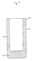
electromagnetic device 100′ of an electromagnetic clutch includes an annularmagnetic housing 110 having a U-shaped cross sections anelectromagnetic coil 120 contained within the annularmagnetic housing 110 and an annular supportingplate 130 to which the annularmagnetic housing 110 is firmly fixed by, for example, spot welding. The annularmagnetic housing 110 includes an inner annularcylindrical portion 111, an outer annular cylindrical 112 and an annularbottom end portion 113 connecting one end of the inner and outer annularcylindrical portions plate 130 is firmly secured to the axial end surface of a compressor housing (not shown) by a plurality of rivets (not shown). The thickness of the inner annularcylindrical portion 111 of thehousing 110 is designed to be slightly greater than the thickness of the outer annularcylindrical portion 112 of thehousing 110. Ahole 114 is formed at a certain region of thebottom end portion 113 of the annularmagnetic housing 110. Asurface 115 concentric with thehole 114 is formed at abottom end portion 113 by using acutting tool 400 as shown in Figure 4. Abottom surface 115a of thesurface 115 is slightly inclined towards a centre thereof. Consequently, anannular flange 116 inwardly extending from inner side wall 115b of thesurface 115 is formed at a certain region of thebottom end portion 113 of annularmagnetic housing 110. - A
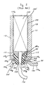
grommet 140 made of insulating material, for example, a rubber member, penetrates through thehole 114. Thegrommet 140 includes an upper cylindrical portion 141, a lowercylindrical portion 142 connected to a bottom end of the upper cylindrical portion, a truncated conical portion 143 connected to a bottom end of the lowercylindrical portion 142, ahole 144 centrally and axially formed there-through and anannular groove 145 formed at a boundary between the upper cylindrical portion 141 and the lowercylindrical portion 142. A diameter of the upper cylindrical portion 141 is designed to be greater than a diameter of the lowercylindrical portion 142. An annular upper surface 145b of thegroove 145 is slightly inclined so as to be along abottom surface 115a of thesurface 115. The diameter of the annular bottom surface 145a of thegroove 145 is slightly greater than a diameter of thehole 114. The diameter of the upper cylindrical portion 141 of thegrommet 140 is slightly greater than the diameter of an inner side wall 115b of thesurface 115. Accordingly, by utilizing elasticity of the rubber member, the upper cylindrical portion 141 of thegrommet 140 is closely disposed within thesurface 115 and theannular groove 145 engages theannular flange 116. - The annular supporting
plate 130 includes a shallow cup-shaped region 130a defining anindent 131 at its upper side and anannular region 130b radially extending from a periphery of the shallow cup-shaped region 130a. The annular supportingplate 130 is provided with a semicircular cut-outportion 131a formed at anannular region 130b thereof. The semicircular cut-outportion 131a is aligned with thehole 114 to dispose the lowercylindrical portion 142 of thegrommet 140 therein when thebottom end portion 113 of the annularmagnetic housing 110 is firmly fixed to theannular region 130b of the annular supportingplate 130. The annularmagnetic housing 110 is firmly fixed to theannular region 131a of the annular supportingplate 130 by spot welding, thereby forming a plurality ofspot welds 132 as shown in Figure 1. - The
annular flange 116 and semicircular cut-outportion 131a constitute anengaging mechanism 200′ which can engage with theannular groove 145 of thegrommet 140. - The
hole 144 of thegrommet 140 includes a truncated cone-shaped section 144a at its upper side and cylindrical section 144b at its lower side. The truncated cone-shaped section 144a gradually narrows downwardly and is connected to the cylindrical section 144b at its bottom end. - A cavity 110a defined by the annular
magnetic housing 110 and thegrommet 140 is filled with heatedepoxy resin 150, which is hardened upon elapse of time with cooling, so as to fix thecoil 120 therewithin. - As shown in figure 1, a pair of tiny
identical projections 160 are formed at a bottom end surface of the annular supportingplate 130 so as to be received within a pair of tiny identical indents (not shown) formed at the axial end surface of the refrigerant compressor housing. Thereby, rotational movement of theelectromagnetic device 100′ is prevented. - A
wire 170 led from a bottom end portion of theelectromagnetic coil 120 closely penetrates through thehole 144 of thegrommet 140. Aterminal end 171 of thewire 170 is connected to aplug 180 which is connected to a terminal end of another wire (not shown) leading from a control apparatus (not shown) of an automobile air conditioning system. - Accordingly, the
grommet 140 is used as an insulator, as a plug which can prevent leakage of the heatedepoxy resin 150 through thehole 114 from the inside of thehousing 110 and as a holder which can firmly hold thewire 170. - By virtue of operation of the control apparatus of the automobile air conditioning system, the
electromagnetic coil 120 is intermittently activated in response to the automobile air conditioning demand. Therefore, power of the automobile engine is intermittently transmitted to the refrigerant compressor through the electromagnetic clutch in response to the automobile air conditioning demand. - The
engaging mechanism 200′ is formed as follows. First, referring to Figures 3 and 4,hole 114 is formed in thebottom end portion 113 of the annularmagnetic housing 110 by punching out by press working. Then, referring to Figures 4 and 5, thesurface 115 concentric with thehole 114 is formed at thebottom end portion 113 of the annularmagnetic housing 110 by using acutting tool 400. Consequently, theannular flange 116 is formed at a bottom end surface of thebottom end portion 113 of the annularmagnetic housing 110 as shown in Figure 5. Next, referring to Figures 1 and 2, a semi-circular cut-outportion 131a is formed at anannular region 130b of the annular supportingplate 130 by punching out by press working. Finally, thebottom end portion 113 of thehousing 110 is firmly fixed to theannular region 130b of the supportingplate 130 by spot welding with thehole 114 aligned with the semicircular cut-outportion 131a as shown in Figure 1. Thus, theengaging mechanism 200′ is formed at the bottom end surface of thebottom end portion 113 of the annularmagnetic housing 110 as shown in Figure 2. - As described above, in this prior art embodiment, it is required not only to use only the press but also to use a
cutter 400 of Figure 4 in order to form theengaging mechanism 200′. Therefore, a manufacturing process of theelectromagnetic device 100′ of the electromagnetic clutch is complicated. - Accordingly, it is an object of this invention to provide a simple manufacturing process of an electromagnetic device of an electromagnetic clutch.
- According to the invention, an electromagnetic clutch including an electromagnetic device comprising an annular magnetic housing having a U-shaped cross section, an annular supporting plate on which a bottom end portion of the annular magnetic housing is firmly attached, and a grommet having an annular groove at its outer peripheral surface, with engaging means engaging with the annular groove of the grommet; is characterised in that the engaging mechanism is provided by a first circular hole formed through the bottom end portion of the annular magnetic housing and a concentric second circular hole formed through the annular supporting plate, the diameter of the first circular hole being greater than the diameter of the second circular hole, thereby forming on the annular supporting plate a radially inwardly projecting annular projection which is received in the annular groove.
- The first and second circular holes are preferably formed by press working.
- In the accompanying drawings:
- Figure 1 illustrates a bottom plan view of an electromagnetic device of an electromagnetic clutch in accordance with one prior art embodiment;
- Figure 2 illustrates an enlarged fragmentary vertical sectional view taken on the line 2-2 in Figure 1;
- Figures 3 to 5 illustrate the U-shaped annular magnetic housing in each manufacturing process of the prior art embodiment;
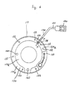
- Figure 6 illustrates a bottom plan view of an electromagnetic clutch in accordance with one embodiment of the present invention;
- Figure 7 illustrates an enlarged fragmentary vertical sectional view taken on the line 7-7 in Figure 6; and,
- Figures 8 to 10 illustrate the electromagnetic device in each manufacturing process of the one embodiment of the present invention.
- Figures 6 and 7 illustrate the structure of an electromagnetic device of an electromagnetic clutch in accordance with one embodiment of the present invention. In Figures 6 the same numerals are used to denote the corresponding elements shown in Figures 1 and 2, and thus an explanation thereof is omitted.
- Referring to Figures 6 and 7, an
electromagnetic device 10 of an electromagnetic clutch includes an annularmagnetic housing 110 having ahole 114 formed at abottom end portion 113 thereof and agrommet 24 penetrates through thehole 114. Thegrommet 24 made of insulating material, for example, a rubber member, comprises acylindrical portion 241, a truncated cone-shaped portion 242, ahole 144 centrally and axially formed therethrough and anannular groove 243 formed at a boundary between thecylindrical portion 241 and the truncated cone-shaped portion 242. - An annular supporting
plate 130 is provided with acircular hole 133 formed at anannular region 130b thereof. The annularmagnetic housing 110 is firmly fixed to theannular region 130b of the annular supportingplate 130 by spot welding with thehole 114 concentrically aligned with thehole 133. The diameter of thehole 133 is smaller than the diameter of thehole 114. Consequently, anannular projection 134, projecting from an inner peripheral surface of thehole 114, is formed at the bottom end surface of theend portion 113 of thehousing 110. The function of theannular projection 134 is similar to the function of the engagingmechanism 200′ in the prior art. - The diameter of the
circular hole 133 is slightly smaller than the diameter of thebottom end surface 243a of thegroove 243. The width of thegroove 243 is slightly smaller than the thickness of theannular region 130b of the annular supportingplate 130. Furthermore, the diameter of thecylindrical portion 241 of thegrommet 24 is designed to be slightly greater than the diameter of thehole 114. Accordingly, by utilizing the elasticity of the rubber member, thecylindrical portion 241 of thegrommet 24 is closely disposed within thehole 114 and theannular groove 243 of thegrommet 24 is closely engaged with theannular projection 134. - The engaging
mechanism 200 is formed as follows. First, referring to Figures 3 and 8, thehole 114 is formed at thebottom end portion 113 of thehousing 110 by punching out by press working. Then, referring to Figure 9, thehole 133 is formed at anannular region 130b of the supportingplate 130 by punching out by press working. Finally, thebottom end portion 113 of thehousing 110 is firmly fixed to theannular region 130b of the supportingplate 130 by spot welding with thehole 114 concentrically aligned with thehole 133. Consequently, theannular projection 134, projecting from the inner peripheral surface of thehole 114, is formed at the bottom end surface of thebottom end portion 113 of thehousing 110 as shown in Figure 9. Thus, engagingmechanism 200 is formed at the bottom end surface ofbottom end portion 113 ofhousing 110 as shown in Figure 9. - Furthermore, referring to Figures 9 and 10, by utilizing the elasticity of the rubber member, the
cylindrical portion 241 of thegrommet 24 is closely disposed within thehole 114, and theannular groove 243 of thegrommet 24 is closely engaged with theannular projection 134. - As described above, in this preferred embodiment of the present invention, it is not required to use any
cutting tool 400, as shown in Figure 4, in order to form the engagingmechanism 200. It is only required to use a press. Therefore, theelectromagnetic device 10 of the electromagnetic clutch is manufactured by a simple manufacturing process. - Furthermore, since the diameter of the
circular hole 133 of the supportingplate 130 is slightly smaller than the diameter of thebottom end surface 243a of thegroove 243 of thegrommet 24, the area of the cut-out region defining thecircular hole 133 is sufficiently small in comparison with the area of the cut-out cutout region defining the semicircular cut-outportion 131a of the supporting plate of the prior art embodiment. Therefore, the strength of the supportingplate 130 is increased in comparison with the supporting plate of the prior art embodiment. In addition, the spot welding can further be done at anannular region 130b of the supportingplate 130 as shown in Figure 6. Thereby, thebottom end portion 113 ofhousing 110 is further firmly fixed to theannular region 130b of the supportingplate 130.
Claims (2)
Applications Claiming Priority (2)
| Application Number | Priority Date | Filing Date | Title |
|---|---|---|---|
| JP119152/89U | 1989-10-13 | ||
| JP1989119152U JP2568051Y2 (en) | 1989-10-13 | 1989-10-13 | Exciter for electromagnetic clutch |
Publications (2)
| Publication Number | Publication Date |
|---|---|
| EP0422962A1 true EP0422962A1 (en) | 1991-04-17 |
| EP0422962B1 EP0422962B1 (en) | 1993-08-25 |
Family
ID=14754207
Family Applications (1)
| Application Number | Title | Priority Date | Filing Date |
|---|---|---|---|
| EP90311252A Expired - Lifetime EP0422962B1 (en) | 1989-10-13 | 1990-10-15 | Electromagnetic clutch |
Country Status (8)
| Country | Link |
|---|---|
| US (1) | US5121093A (en) |
| EP (1) | EP0422962B1 (en) |
| JP (1) | JP2568051Y2 (en) |
| KR (1) | KR0160289B1 (en) |
| CN (1) | CN1021475C (en) |
| AU (1) | AU629413B2 (en) |
| CA (1) | CA2027610C (en) |
| DE (1) | DE69002912T2 (en) |
Cited By (9)
| Publication number | Priority date | Publication date | Assignee | Title |
|---|---|---|---|---|
| EP0806583A1 (en) * | 1996-05-07 | 1997-11-12 | Sanden Corporation | Electromagnetic clutch |
| US5889455A (en) * | 1996-10-07 | 1999-03-30 | Sanden Corporation | Electromagnet in which a coil member is inclined in an annular groove of a core |
| US6091590A (en) * | 1995-03-08 | 2000-07-18 | Sanden Corporation | Electromagnetic coil assembly for electromagnetic apparatus |
| FR2805658A1 (en) * | 2000-02-29 | 2001-08-31 | Sanden Corp | ELECTROMAGNET ASSEMBLY FOR ELECTROMAGNETIC APPARATUS |
| US6587024B2 (en) | 2000-02-29 | 2003-07-01 | Sanden Corporation | Electromagnetic coil assembly for electromagnetic apparatus |
| US6707365B2 (en) | 2001-10-30 | 2004-03-16 | Sanden Corporation | Electromagnetic coupling apparatus |
| US6867675B2 (en) | 2000-02-29 | 2005-03-15 | Sanden Corporation | Electromagnet assembly for electromagnetic apparatus |
| EP1646058A1 (en) * | 2004-10-08 | 2006-04-12 | Halla Climate Control Corporation | Field coil assembly of an electromagnetic clutch for a compressor |
| EP3291252A1 (en) * | 2016-08-09 | 2018-03-07 | Ogura Clutch Co., Ltd. | Exciting device for electromagnetic connection device |
Families Citing this family (8)
| Publication number | Priority date | Publication date | Assignee | Title |
|---|---|---|---|---|
| JPH0589971U (en) * | 1992-05-21 | 1993-12-07 | サンデン株式会社 | Electromagnetic clutch and electromagnet ring member |
| US5320206A (en) * | 1993-05-03 | 1994-06-14 | Ogura Corporation | Coil mounting and terminals for an electromagnetic clutch |
| CN1097454C (en) * | 1996-07-18 | 2003-01-01 | 颜培克 | Weight-lossing essence for human body |
| JP2001332418A (en) | 2000-05-23 | 2001-11-30 | Sanden Corp | Coil bobbin |
| KR100652246B1 (en) * | 2005-07-20 | 2006-12-01 | 우리산업 주식회사 | A electric power connection part of magnetic clutch field coil assembly connected with vehicle compressor |
| KR100827550B1 (en) * | 2007-04-20 | 2008-05-07 | 주식회사 신라공업 | Connector installation structure improving automobile magnet clutch electric coil housing |
| CN101956854B (en) * | 2009-07-15 | 2012-10-24 | 浙江三花股份有限公司 | Electric control valve and valve body device thereof |
| JP6857967B2 (en) * | 2016-04-05 | 2021-04-14 | 小倉クラッチ株式会社 | Seal structure of lead wire for electromagnet |
Citations (4)
| Publication number | Priority date | Publication date | Assignee | Title |
|---|---|---|---|---|
| US3016118A (en) * | 1958-12-29 | 1962-01-09 | Reeves Instrument Corp | Electromagnetic clutches and brakes |
| US3036679A (en) * | 1958-01-17 | 1962-05-29 | Novi Equipment Co | Magnetic clutch structure |
| GB1119006A (en) * | 1966-01-12 | 1968-07-03 | Pier Luigi De Stefain | Electromagnetic valve for instance for a gas safety device, electromagnet therefor, and methods of manufacture thereof |
| US3565223A (en) * | 1969-06-09 | 1971-02-23 | Pitts Ind Inc | Resilient lining for magnetic clutch |
Family Cites Families (4)
| Publication number | Priority date | Publication date | Assignee | Title |
|---|---|---|---|---|
| US3833871A (en) * | 1973-11-19 | 1974-09-03 | Eaton Corp | Coil connections for an electromagnetic drive |
| US4432446A (en) * | 1980-06-28 | 1984-02-21 | Nippondenso Co., Ltd. | Electromagnetic coupling apparatus |
| US4547757A (en) * | 1981-04-17 | 1985-10-15 | Matsushita Electric Industrial Co., Ltd. | Electromagnet yoke structure |
| JPS639786U (en) * | 1986-07-07 | 1988-01-22 |
-
1989
- 1989-10-13 JP JP1989119152U patent/JP2568051Y2/en not_active Expired - Lifetime
-
1990
- 1990-10-12 AU AU64578/90A patent/AU629413B2/en not_active Expired
- 1990-10-13 KR KR1019900016373A patent/KR0160289B1/en not_active IP Right Cessation
- 1990-10-13 CN CN90108462.XA patent/CN1021475C/en not_active Expired - Lifetime
- 1990-10-15 CA CA002027610A patent/CA2027610C/en not_active Expired - Lifetime
- 1990-10-15 EP EP90311252A patent/EP0422962B1/en not_active Expired - Lifetime
- 1990-10-15 US US07/597,028 patent/US5121093A/en not_active Expired - Lifetime
- 1990-10-15 DE DE90311252T patent/DE69002912T2/en not_active Expired - Lifetime
Patent Citations (4)
| Publication number | Priority date | Publication date | Assignee | Title |
|---|---|---|---|---|
| US3036679A (en) * | 1958-01-17 | 1962-05-29 | Novi Equipment Co | Magnetic clutch structure |
| US3016118A (en) * | 1958-12-29 | 1962-01-09 | Reeves Instrument Corp | Electromagnetic clutches and brakes |
| GB1119006A (en) * | 1966-01-12 | 1968-07-03 | Pier Luigi De Stefain | Electromagnetic valve for instance for a gas safety device, electromagnet therefor, and methods of manufacture thereof |
| US3565223A (en) * | 1969-06-09 | 1971-02-23 | Pitts Ind Inc | Resilient lining for magnetic clutch |
Cited By (13)
| Publication number | Priority date | Publication date | Assignee | Title |
|---|---|---|---|---|
| US6091590A (en) * | 1995-03-08 | 2000-07-18 | Sanden Corporation | Electromagnetic coil assembly for electromagnetic apparatus |
| US5812044A (en) * | 1996-05-07 | 1998-09-22 | Sanden Corporation | Electromagnetic clutch |
| EP0806583A1 (en) * | 1996-05-07 | 1997-11-12 | Sanden Corporation | Electromagnetic clutch |
| US5889455A (en) * | 1996-10-07 | 1999-03-30 | Sanden Corporation | Electromagnet in which a coil member is inclined in an annular groove of a core |
| US6867675B2 (en) | 2000-02-29 | 2005-03-15 | Sanden Corporation | Electromagnet assembly for electromagnetic apparatus |
| FR2805658A1 (en) * | 2000-02-29 | 2001-08-31 | Sanden Corp | ELECTROMAGNET ASSEMBLY FOR ELECTROMAGNETIC APPARATUS |
| US6587024B2 (en) | 2000-02-29 | 2003-07-01 | Sanden Corporation | Electromagnetic coil assembly for electromagnetic apparatus |
| US6842102B2 (en) | 2000-02-29 | 2005-01-11 | Sanden Corporation | Electromagnetic coil assembly for electromagnetic apparatus |
| US6707365B2 (en) | 2001-10-30 | 2004-03-16 | Sanden Corporation | Electromagnetic coupling apparatus |
| EP1646058A1 (en) * | 2004-10-08 | 2006-04-12 | Halla Climate Control Corporation | Field coil assembly of an electromagnetic clutch for a compressor |
| US7138895B2 (en) | 2004-10-08 | 2006-11-21 | Halla Climate Control Corporation | Field coil assembly for an electromagnetic clutch for a compressor |
| EP3291252A1 (en) * | 2016-08-09 | 2018-03-07 | Ogura Clutch Co., Ltd. | Exciting device for electromagnetic connection device |
| US10192664B2 (en) | 2016-08-09 | 2019-01-29 | Ogura Clutch Co., Ltd. | Exciting device for electromagnetic connection device |
Also Published As
| Publication number | Publication date |
|---|---|
| DE69002912T2 (en) | 1994-01-20 |
| JPH0359528U (en) | 1991-06-12 |
| CN1050926A (en) | 1991-04-24 |
| CN1021475C (en) | 1993-06-30 |
| CA2027610A1 (en) | 1991-04-14 |
| AU6457890A (en) | 1991-04-18 |
| CA2027610C (en) | 1995-05-09 |
| US5121093A (en) | 1992-06-09 |
| EP0422962B1 (en) | 1993-08-25 |
| JP2568051Y2 (en) | 1998-04-08 |
| DE69002912D1 (en) | 1993-09-30 |
| KR0160289B1 (en) | 1998-12-01 |
| AU629413B2 (en) | 1992-10-01 |
Similar Documents
| Publication | Publication Date | Title |
|---|---|---|
| EP0422962B1 (en) | Electromagnetic clutch | |
| US6352317B1 (en) | Solenoid coil structure and interconnection | |
| US5307038A (en) | Electromagnetic coupling apparatus | |
| CN110048533B (en) | Electric motor and method for manufacturing the same | |
| US4432446A (en) | Electromagnetic coupling apparatus | |
| JP3099288B2 (en) | Electromagnetic coupling device | |
| EP0236254A2 (en) | Brush holder for dynamoelectric machines | |
| US5278468A (en) | Structure for a DC motor with an electronic commutation | |
| CA2199302C (en) | Switch having a temperature-dependent switching mechanism | |
| US4882558A (en) | Solenoid assembly | |
| US6833650B2 (en) | Plane commutator of motor having a base made of conductive powder | |
| US6138809A (en) | Insulated electromagnetic coil for electromagnetic clutch | |
| KR20010090528A (en) | Plane commutator and method of manufacturing the same | |
| US4075626A (en) | Alarm buzzer | |
| EP1439304B1 (en) | Wire connecting structure of electromagnetic switch of starter | |
| JPH0334226B2 (en) | ||
| EP3291252B1 (en) | Exciting device for electromagnetic connection device | |
| GB2313484A (en) | Solenoid assembly for anti-lock braking system | |
| US5659282A (en) | Cylindrical fuse holder with a socket movable axially in the holder | |
| CN111384811A (en) | Motor with a stator having a stator core | |
| GB2232011A (en) | Terminal adapter in an electric motor | |
| EP0769794B1 (en) | Electrical component protection device | |
| CN216489944U (en) | Stator and motor using same | |
| JP2003180047A (en) | Brushless motor | |
| JPH084710Y2 (en) | Car plug |
Legal Events
| Date | Code | Title | Description |
|---|---|---|---|
| PUAI | Public reference made under article 153(3) epc to a published international application that has entered the european phase |
Free format text: ORIGINAL CODE: 0009012 |
|
| AK | Designated contracting states |
Kind code of ref document: A1 Designated state(s): DE FR GB IT SE |
|
| 17P | Request for examination filed |
Effective date: 19911011 |
|
| 17Q | First examination report despatched |
Effective date: 19921204 |
|
| GRAA | (expected) grant |
Free format text: ORIGINAL CODE: 0009210 |
|
| AK | Designated contracting states |
Kind code of ref document: B1 Designated state(s): DE FR GB IT SE |
|
| REF | Corresponds to: |
Ref document number: 69002912 Country of ref document: DE Date of ref document: 19930930 |
|
| ITF | It: translation for a ep patent filed |
Owner name: JACOBACCI CASETTA & PERANI S.P.A. |
|
| ET | Fr: translation filed | ||
| PLBE | No opposition filed within time limit |
Free format text: ORIGINAL CODE: 0009261 |
|
| STAA | Information on the status of an ep patent application or granted ep patent |
Free format text: STATUS: NO OPPOSITION FILED WITHIN TIME LIMIT |
|
| 26N | No opposition filed | ||
| EAL | Se: european patent in force in sweden |
Ref document number: 90311252.2 |
|
| REG | Reference to a national code |
Ref country code: GB Ref legal event code: IF02 |
|
| PGFP | Annual fee paid to national office [announced via postgrant information from national office to epo] |
Ref country code: DE Payment date: 20091008 Year of fee payment: 20 Ref country code: SE Payment date: 20091007 Year of fee payment: 20 |
|
| PGFP | Annual fee paid to national office [announced via postgrant information from national office to epo] |
Ref country code: FR Payment date: 20091029 Year of fee payment: 20 Ref country code: GB Payment date: 20091014 Year of fee payment: 20 Ref country code: IT Payment date: 20091017 Year of fee payment: 20 |
|
| REG | Reference to a national code |
Ref country code: GB Ref legal event code: PE20 Expiry date: 20101014 |
|
| EUG | Se: european patent has lapsed | ||
| PG25 | Lapsed in a contracting state [announced via postgrant information from national office to epo] |
Ref country code: GB Free format text: LAPSE BECAUSE OF EXPIRATION OF PROTECTION Effective date: 20101014 |
|
| PG25 | Lapsed in a contracting state [announced via postgrant information from national office to epo] |
Ref country code: DE Free format text: LAPSE BECAUSE OF EXPIRATION OF PROTECTION Effective date: 20101015 |