EP0422303A1 - Hinterkantenklappen eines Flugzeuges - Google Patents
Hinterkantenklappen eines Flugzeuges Download PDFInfo
- Publication number
- EP0422303A1 EP0422303A1 EP19890310514 EP89310514A EP0422303A1 EP 0422303 A1 EP0422303 A1 EP 0422303A1 EP 19890310514 EP19890310514 EP 19890310514 EP 89310514 A EP89310514 A EP 89310514A EP 0422303 A1 EP0422303 A1 EP 0422303A1
- Authority
- EP
- European Patent Office
- Prior art keywords
- flap
- trailing edge
- pivotal attachment
- flap portion
- primary
- Prior art date
- Legal status (The legal status is an assumption and is not a legal conclusion. Google has not performed a legal analysis and makes no representation as to the accuracy of the status listed.)
- Granted
Links
Images

Classifications
-
- B—PERFORMING OPERATIONS; TRANSPORTING
- B64—AIRCRAFT; AVIATION; COSMONAUTICS
- B64C—AEROPLANES; HELICOPTERS
- B64C9/00—Adjustable control surfaces or members, e.g. rudders
- B64C9/14—Adjustable control surfaces or members, e.g. rudders forming slots
- B64C9/16—Adjustable control surfaces or members, e.g. rudders forming slots at the rear of the wing
- B64C9/20—Adjustable control surfaces or members, e.g. rudders forming slots at the rear of the wing by multiple flaps
Definitions
- This invention relates to wing trailing edge flaps for aircraft. More particularly it relates to a flap system which is readily adaptable, in operation, from a single slotted to a double slotted configuration.
- Single slotted trailing edge flaps are well known which are configured such that they are movable from a datum cruise position where they conform to, and therefore define, the wing trailing edge aerodynamic profile to selected take-off, approach and landing settings where they are translated rearwardly relative to the wing fixed trailing edge structure with an associated downward angular displacement. Consequently, a convergent slot is formed between the wing trailing edge structure and the exposed leading edge of the flap, the resultant induced flow through the slot enhancing the flow and thus the aerodynamic lift over the wing upper surface particularly in the low speed handling mode.
- a single slotted flap may perform adequately.
- Changes in touchdown attitude and approach speed arising as a consequence of these changes may demand a trailing edge flap system of improved performance which the single slotted type may not be capable of achieving.
- This shortcoming may beneficially be overcome by a double slotted flap.
- the maximum possible commonality between the alternative flap systems should be achieved in terms of overall flap geometry and operating mechanism so that (a) the flap will still be contained within the same aerodynamic profile envelope when in its stowed position (b) will extend, unchanged, as a single slotted device up to and including its take-off setting but whereby the flap is so configured and its associated operating mechanism modified thereby achieving a double slotted configuration in the approach and landing modes. It is the object of the present invention to achieve such an arrangement.
- British Patent 560,996 teaches the use of a main flap and a secondary flap and where the secondary flap is moveable rearwardly to define a slot.
- the secondary flap is mounted on runners contained within the main flap.
- British Patent 775,603 relates to a main and auxiliary flap system moveable as a unit for the take-off and approach setting but with the auxiliary flap moveable with respect to the main flap in the landing position.
- the angular deflection of the auxiliary flap is defined in one embodiment by a roller on a single flap arm (11) engaging a stationary guide path 7. Only a single auxiliary flap support is illustrated.
- British Patent 1,227,316 teaches a high lift flap where a tab is separated from a main flap to define a slot by means of a push-pull rod at least part of which turns about its longitudinal axis to cause deflection.
- US Patent 4,049,219 teaches a double element trailing edge flap with the main flap moveable by a four-bar linkage and the aft flap programmed with a linkage pivotally mounted to wing support structure.
- a double element trailing edge flap assembly (14) for an aircraft wing of the type comprising a primary flap portion (15) and an interconnected auxiliary flap portion (16) configured to be relatively moveable and angularly displaced with respect to the primary portion, in which the flap assembly is extendable rearwardly by actuating means (24, 26, 27) from its stowed position up to and including a take-off setting and a single convergent slot is formed between the flap and the wing trailing edge without relative movement between the respective flap portions and to a landing mode setting where continuing rearward translation of the flap assembly effects by attitude control means (41) angular displacement of the auxiliary flap portion relative to the primary flap portion such that a convergent slot (43) is formed therebetween at a pre-defined gap and overlap between the leading edge portion of the auxiliary flap portion and the trailing edge of the primary flap portion characterised in that said angular displacement and said gap and overlap are achieved by a two bar linkage arrangement comprising a first link (34) having a first pivot
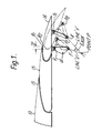
- FIG. 1 this illustrates the preferred geometrical arrangement of linkages interconnecting the auxiliary flap portion 16 to the primary flap portion 15.
- the primary flap portion 15 is shown in stowed position relative to the wing trailing edge 13 of the wing 10. It will be appreciated, however, from the accompanying description of the embodiments, that angular displacement of the auxiliary flap portion 16 can only occur as a function of the displacement of the primary flap portion.
- Reference to Figure 5 will show the flap system fully deployed in the landing mode.
- the linkage geometry for the auxiliary flap is based on the flap in its stowed position relative to the primary flap portion and the angular displacement which it is required to adopt in the landing mode, the extreme range of movement required. In its stowed position when it substantially conforms to the trailing edge configuration of the primary flap 15 only a minimum clearance gap g, will be necessary.
- a minimum clearance gap g will be necessary.
- the primary convergent slot is that formed in similar manner between the primary flap leading edge and the wing.
- the geometry to achieve the desired operating parameters is established thus.
- the auxiliary flap 16 is set at the desired landing mode setting, in this embodiment 20° with the required gaps and overlaps.
- Earth hinge points F and R are located by mounting beam means off the primary flap, as illustrated in Figures 2 and 3 (with the earth points indicated thereon as 32 and 33) where F can be anywhere on line X and R anywhere on line Y where lines X and Y are the perpendicular bisectors of f1 f2, s1 s2 respectively.
- the linkage lengths Ff1 and Rs1 are selected on the basis that Ff1 is the dominant term in setting ⁇ aux in relation to Sf where Sf is the primary flap setting.
- Point P as illustrated is correct for cruise, ie, the stowed position, and landing modes only.
- the point 'd' (indicated as item 40 in Figure 2) is the pivotal attachment point for auxiliary flap drive (via attitude control link 41 in Figure 2) and is located so that it will give the optimum input drive from the flap drive mechanism.
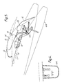
- FIG. 2-5 inclusive there is illustrated an aft portion of an aircraft wing 10 having an upper surface 11, a lower surface 12, a trailing edge portion 13.
- a flap assembly 14 comprising a forward flap element 15 and a rearward auxiliary flap portion 16 are shown in Figure 2 in stowed datum cruise position within the trailing edge portion 13.
- Extending rearwardly from the undersurface of the wing 10 is a mounting beam 17 having an upper diagonal rolling surface 18 for engaging a flap support carriage 19.
- the carriage is in rolling engagement with the mounting beam by means of upper and lower pairs of rollers 20 and 21 respectively.
- the forward flap element 15 is pivotally supported upon the carriage 19 via a fixed depending bracket 22 including a spanwise pivotal attachment 23 to the carriage 19 representing a common pivot axis for the flap and a flap actuating rod 24.
- the rod 24 extends forwardly, its forward extremity including a pivotal attachment 25 to a lever arm 26 extending downwardly from a rotary actuator 27, mounted to the fixed wing structure for rotation about a generally spanwise axis 28.
- the actuating rod includes a flap leading edge attachment assembly 29 for flap attitude control.
- the rear of the forward flap element 14 includes a trailing edge shroud portion 30.
- An auxiliary flap support post 31 depends diagonally from the undersurface of the forward flap element 14 and incorporates pivotal attachments 32 and 33 for respectively mounting auxiliary flap support links 34 and 35, the links being respectively pivotally attached at 36 and 37 to attachment brackets 38 and 39 depending from the flap undersurface.
- the link 34 is triangulated in order to accommodate a pivotal attachment 40 to an attitude control link 41 extending in a forwardly diagonal direction and having a pivotal attachment 42 to the carriage 19.
- the forward flap element and the auxiliary flap combine in the datum cruise condition as illustrated in Figure 2 to effectively form a one element flap assembly which is maintained up to and including the take-off setting at which a single convergent slot is formed between the primary flap portion leading edge and the wing trailing edge portion 13.
- the flap assembly is mechanically configured to define a double slotted flap assembly.
- the rotary actuator 27 via the lever arm 26 and the flap actuating rod 24 will translate the flap assembly 14 in a rearwardly direction with an associated downwards deflection.
- the degree of deflection, as a function of the said rearwards translation is controlled by the progression of the carriage 19 down the rolling surface 18 of the mounting beam 17 driven by the flap actuating rod 24 and whose angular displacement controls the path of the flap leading edge by means of the attachment assembly 29.
- the operating mechanism is contained within an underwing fairing 44 and includes linkage arrangements 45 interconnected to the flap operating mechanism so that at least the rearward portion is angularly deployed in conjunction with flap movement.
Landscapes
- Engineering & Computer Science (AREA)
- Aviation & Aerospace Engineering (AREA)
- Tires In General (AREA)
- Transmission Devices (AREA)
Priority Applications (2)
| Application Number | Priority Date | Filing Date | Title |
|---|---|---|---|
| DE1989619850 DE68919850T2 (de) | 1989-10-13 | 1989-10-13 | Hinterkantenklappen eines Flugzeuges. |
| EP19890310514 EP0422303B1 (de) | 1989-10-13 | 1989-10-13 | Hinterkantenklappen eines Flugzeuges |
Applications Claiming Priority (1)
| Application Number | Priority Date | Filing Date | Title |
|---|---|---|---|
| EP19890310514 EP0422303B1 (de) | 1989-10-13 | 1989-10-13 | Hinterkantenklappen eines Flugzeuges |
Publications (2)
| Publication Number | Publication Date |
|---|---|
| EP0422303A1 true EP0422303A1 (de) | 1991-04-17 |
| EP0422303B1 EP0422303B1 (de) | 1994-12-07 |
Family
ID=8202819
Family Applications (1)
| Application Number | Title | Priority Date | Filing Date |
|---|---|---|---|
| EP19890310514 Expired - Lifetime EP0422303B1 (de) | 1989-10-13 | 1989-10-13 | Hinterkantenklappen eines Flugzeuges |
Country Status (2)
| Country | Link |
|---|---|
| EP (1) | EP0422303B1 (de) |
| DE (1) | DE68919850T2 (de) |
Cited By (1)
| Publication number | Priority date | Publication date | Assignee | Title |
|---|---|---|---|---|
| US5270077A (en) * | 1991-12-13 | 1993-12-14 | General Electric Company | Method for producing flat CVD diamond film |
Families Citing this family (1)
| Publication number | Priority date | Publication date | Assignee | Title |
|---|---|---|---|---|
| DE102004013296A1 (de) * | 2004-03-18 | 2005-10-13 | Gert Dr.-Ing. Dallach | Geteilte Ruder für Schiffe |
Citations (4)
| Publication number | Priority date | Publication date | Assignee | Title |
|---|---|---|---|---|
| GB775603A (en) * | 1954-02-17 | 1957-05-29 | Konink Nl Vliegtuigenfabriek F | Improvements relating to aircraft wings |
| FR2076043A1 (de) * | 1970-01-12 | 1971-10-15 | Hawker Siddeley Aviat | |
| FR2115468A2 (fr) * | 1970-11-30 | 1972-07-07 | Hawker Siddeley Aviat | Mécanisme de sortie et de rentrée de volet d'aile d'avion |
| US4049219A (en) * | 1975-02-03 | 1977-09-20 | The Boeing Company | Variable pivot trailing edge flap |
-
1989
- 1989-10-13 EP EP19890310514 patent/EP0422303B1/de not_active Expired - Lifetime
- 1989-10-13 DE DE1989619850 patent/DE68919850T2/de not_active Expired - Fee Related
Patent Citations (4)
| Publication number | Priority date | Publication date | Assignee | Title |
|---|---|---|---|---|
| GB775603A (en) * | 1954-02-17 | 1957-05-29 | Konink Nl Vliegtuigenfabriek F | Improvements relating to aircraft wings |
| FR2076043A1 (de) * | 1970-01-12 | 1971-10-15 | Hawker Siddeley Aviat | |
| FR2115468A2 (fr) * | 1970-11-30 | 1972-07-07 | Hawker Siddeley Aviat | Mécanisme de sortie et de rentrée de volet d'aile d'avion |
| US4049219A (en) * | 1975-02-03 | 1977-09-20 | The Boeing Company | Variable pivot trailing edge flap |
Cited By (1)
| Publication number | Priority date | Publication date | Assignee | Title |
|---|---|---|---|---|
| US5270077A (en) * | 1991-12-13 | 1993-12-14 | General Electric Company | Method for producing flat CVD diamond film |
Also Published As
| Publication number | Publication date |
|---|---|
| DE68919850T2 (de) | 1995-05-04 |
| EP0422303B1 (de) | 1994-12-07 |
| DE68919850D1 (de) | 1995-01-19 |
Similar Documents
| Publication | Publication Date | Title |
|---|---|---|
| EP0407159B1 (de) | Landeklappenzusammenbau | |
| US8302913B2 (en) | High-lift system for an aircraft | |
| US4669687A (en) | Airfoil flap member with flap track member | |
| US3743219A (en) | High lift leading edge device | |
| US4995575A (en) | Wing trailing edge flap mechanism | |
| EP1398269B2 (de) | Verfahren und Vorrichtung zur Strömungsbeeinflussung mittels einer Flügelvorderkante mit flexibler Oberfläche | |
| US5158252A (en) | Three-position variable camber Krueger leading edge flap | |
| US4444368A (en) | Slotted variable camber flap | |
| US4381093A (en) | Flap assembly for aircraft wing | |
| EP0184230A1 (de) | Hinterkantenflügelklappengerät für ein Flugzeug | |
| US4434959A (en) | Airfoil flap assembly with flap track member | |
| EP2134597A1 (de) | Flügel | |
| JPS647920B2 (de) | ||
| GB2186849A (en) | Leading edge arrangements for aircraft wings | |
| USRE32907E (en) | Airfoil flap assembly with flap track member | |
| US4361299A (en) | Variable camber wings | |
| EP3575206A1 (de) | System zum antrieb einer klappenanordnung zwischen einer eingezogenen position und einer erweiterten position | |
| EP0422303B1 (de) | Hinterkantenklappen eines Flugzeuges | |
| US20200070954A1 (en) | Wing system for an aircraft with a flow body and a cover panel | |
| EP0081610B1 (de) | Klappenanordnung für Flugzeugflügel | |
| US4848707A (en) | Wing leading edge arrangements for aircraft | |
| EP0359481A2 (de) | In den Flugzeugrumpf eingebauter Hinterkantenklappenantrieb | |
| EP0469910A1 (de) | Schwingungsdämpfungsanordnung eines Flugzeuges | |
| GB2060520A (en) | Variable Camber Wings | |
| US2609166A (en) | Airplane flap supporting and control mechanism |
Legal Events
| Date | Code | Title | Description |
|---|---|---|---|
| PUAI | Public reference made under article 153(3) epc to a published international application that has entered the european phase |
Free format text: ORIGINAL CODE: 0009012 |
|
| AK | Designated contracting states |
Kind code of ref document: A1 Designated state(s): DE FR GB |
|
| 17P | Request for examination filed |
Effective date: 19910715 |
|
| RAP3 | Party data changed (applicant data changed or rights of an application transferred) |
Owner name: BRITISH AEROSPACE PUBLIC LIMITED COMPANY |
|
| 17Q | First examination report despatched |
Effective date: 19930408 |
|
| GRAA | (expected) grant |
Free format text: ORIGINAL CODE: 0009210 |
|
| AK | Designated contracting states |
Kind code of ref document: B1 Designated state(s): DE FR GB |
|
| REF | Corresponds to: |
Ref document number: 68919850 Country of ref document: DE Date of ref document: 19950119 |
|
| ET | Fr: translation filed | ||
| PLBE | No opposition filed within time limit |
Free format text: ORIGINAL CODE: 0009261 |
|
| STAA | Information on the status of an ep patent application or granted ep patent |
Free format text: STATUS: NO OPPOSITION FILED WITHIN TIME LIMIT |
|
| 26N | No opposition filed | ||
| REG | Reference to a national code |
Ref country code: GB Ref legal event code: IF02 |
|
| REG | Reference to a national code |
Ref country code: GB Ref legal event code: 732E |
|
| REG | Reference to a national code |
Ref country code: FR Ref legal event code: TP |
|
| PGFP | Annual fee paid to national office [announced via postgrant information from national office to epo] |
Ref country code: FR Payment date: 20040913 Year of fee payment: 16 |
|
| PGFP | Annual fee paid to national office [announced via postgrant information from national office to epo] |
Ref country code: GB Payment date: 20040916 Year of fee payment: 16 |
|
| PGFP | Annual fee paid to national office [announced via postgrant information from national office to epo] |
Ref country code: DE Payment date: 20040917 Year of fee payment: 16 |
|
| PG25 | Lapsed in a contracting state [announced via postgrant information from national office to epo] |
Ref country code: GB Free format text: LAPSE BECAUSE OF NON-PAYMENT OF DUE FEES Effective date: 20051013 |
|
| PG25 | Lapsed in a contracting state [announced via postgrant information from national office to epo] |
Ref country code: DE Free format text: LAPSE BECAUSE OF NON-PAYMENT OF DUE FEES Effective date: 20060503 |
|
| GBPC | Gb: european patent ceased through non-payment of renewal fee |
Effective date: 20051013 |
|
| PG25 | Lapsed in a contracting state [announced via postgrant information from national office to epo] |
Ref country code: FR Free format text: LAPSE BECAUSE OF NON-PAYMENT OF DUE FEES Effective date: 20060630 |
|
| REG | Reference to a national code |
Ref country code: FR Ref legal event code: ST Effective date: 20060630 |