EP0420863B1 - Internal combustion engine with at least one charger of positive displacement design - Google Patents
Internal combustion engine with at least one charger of positive displacement design Download PDFInfo
- Publication number
- EP0420863B1 EP0420863B1 EP89906069A EP89906069A EP0420863B1 EP 0420863 B1 EP0420863 B1 EP 0420863B1 EP 89906069 A EP89906069 A EP 89906069A EP 89906069 A EP89906069 A EP 89906069A EP 0420863 B1 EP0420863 B1 EP 0420863B1
- Authority
- EP
- European Patent Office
- Prior art keywords
- charger
- internal combustion
- engine
- combustion engine
- rotary piston
- Prior art date
- Legal status (The legal status is an assumption and is not a legal conclusion. Google has not performed a legal analysis and makes no representation as to the accuracy of the status listed.)
- Expired - Lifetime
Links
Images


Classifications
-
- F—MECHANICAL ENGINEERING; LIGHTING; HEATING; WEAPONS; BLASTING
- F02—COMBUSTION ENGINES; HOT-GAS OR COMBUSTION-PRODUCT ENGINE PLANTS
- F02B—INTERNAL-COMBUSTION PISTON ENGINES; COMBUSTION ENGINES IN GENERAL
- F02B33/00—Engines characterised by provision of pumps for charging or scavenging
- F02B33/32—Engines with pumps other than of reciprocating-piston type
- F02B33/34—Engines with pumps other than of reciprocating-piston type with rotary pumps
- F02B33/36—Engines with pumps other than of reciprocating-piston type with rotary pumps of positive-displacement type
- F02B33/38—Engines with pumps other than of reciprocating-piston type with rotary pumps of positive-displacement type of Roots type
-
- F—MECHANICAL ENGINEERING; LIGHTING; HEATING; WEAPONS; BLASTING
- F01—MACHINES OR ENGINES IN GENERAL; ENGINE PLANTS IN GENERAL; STEAM ENGINES
- F01L—CYCLICALLY OPERATING VALVES FOR MACHINES OR ENGINES
- F01L1/00—Valve-gear or valve arrangements, e.g. lift-valve gear
- F01L1/44—Multiple-valve gear or arrangements, not provided for in preceding subgroups, e.g. with lift and different valves
- F01L1/443—Multiple-valve gear or arrangements, not provided for in preceding subgroups, e.g. with lift and different valves comprising a lift valve and at least one rotary valve
-
- F—MECHANICAL ENGINEERING; LIGHTING; HEATING; WEAPONS; BLASTING
- F02—COMBUSTION ENGINES; HOT-GAS OR COMBUSTION-PRODUCT ENGINE PLANTS
- F02B—INTERNAL-COMBUSTION PISTON ENGINES; COMBUSTION ENGINES IN GENERAL
- F02B2275/00—Other engines, components or details, not provided for in other groups of this subclass
- F02B2275/14—Direct injection into combustion chamber
Definitions
- the invention relates to a reciprocating internal combustion engine with at least one rotary piston supercharger according to the preamble of claim 1, as is known from GB-A-403 245.
- a four-bladed vane charger is arranged above the engine cylinder.
- the rotor guiding the four vanes is arranged in an eccentrically offset sleeve rotating at the same speed, the vanes being supported by spring and centrifugal forces being in constant contact with the inner surface of this sleeve. Together with two side end caps, four chambers with variable volume during one revolution are thus formed.
- the respective charging chamber is filled with fresh air in the air inlet area of the charger housing and emptied through the respective combustion chamber window into the corresponding cylinder through a window in the sleeve in the area of a loading chamber, which is assigned to the combustion chamber opening of one of the four cylinders.
- the closed part of the sleeve seals the combustion chamber during the high pressure process.
- the burned gases are discharged through a standing exhaust valve. Filling and emptying take place in phase with the piston movement, for which purpose a ratio of 1: 2 each of the supercharger rotors and the exhaust camshaft is provided for the four-stroke engine in relation to the crankshaft speed.
- the known internal combustion engine should also be able to be operated using the two-stroke method.
- the close proximity of the combustion chamber inlet and outlet opening and the inlet flow aimed precisely at the simultaneously open outlet valve have a very negative effect.
- the hot exhaust valve on the side proves to be unfavorable for the knock behavior, especially with the spark plug located far away.
- the wings tilt in their guides, which must therefore be made relatively long, which means that the swallowing volume of the charger is unfavorably small compared to its construction volume, which in turn leads to unfavorably high sliding speeds, friction and wear on the combustion chamber seal.
- the invention has for its object to provide an internal combustion engine of the type mentioned, which allows a good filling of the combustion chamber and its reliable sealing with a compact and simple structure with little construction.
- each supercharger chamber contains more volume than an internal combustion engine cylinder.
- exhaust pipes and exhaust control times which are connected to one another closely behind the exhaust ports and which are greater than the ignition interval, a pressure surge occurs at the exhaust port of the next cylinder in the ignition sequence when the exhaust port of a cylinder is opened via the exhaust system.
- a quantity of fresh gas that has already penetrated into the outlet channel is pushed back into the cylinder, as a result of which a degree of filling is achieved without increasing the loader input power. This effect is effective in the entire speed range.
- the internal combustion engines according to FIGS. 1 to 3 have conventional internal combustion engine housings with engine cylinders, not designed as a crankcase purge pump housing, and conventional crank drives with crankshafts and connecting rods and reciprocating pistons.
- At least one rotary piston loader is arranged in the cylinder head, which is used for gas production serves and controls the gas inlet into the combustion chamber at the same time.
- a two-stroke internal combustion engine 1 has a machine housing 2 with three machine cylinders 3 arranged in series with water cooling, a crankshaft 4, connecting rods 5 and reciprocating pistons 6.
- the engine cylinders 3 are provided at the lower ends of the combustion chambers 7 with outlet slots 8 controlled by the reciprocating pistons 6 and lateral exhaust gas passages 9 extending at least approximately transversely to the engine cylinder axes.
- a cylinder head 10 is arranged on the machine cylinders 3 and is connected to the cooling water circuit of the machine cylinders 3.
- the cylinder head 10 forms the fixed supercharger housing 11 of a rotary piston supercharger 12, which extends over all three machine cylinders 3 in their row arrangement direction and is common to all three machine cylinders 3
- Loader inlet opening 13 (FIG. 1) is provided, which extends approximately over the entire length of the loader housing 11.
- the charger inlet opening 13 is connected with its inflow side to a fresh gas channel extending in the longitudinal direction of the charger, in which a control sleeve is arranged which is pivotably mounted about the longitudinal channel axis and which has a radial window and serves to regulate the charge.
- charger outlet openings 14 opening into the combustion chambers 7 are provided in the jacket wall of the charger housing 11 in the area facing the machine cylinders 3.
- two gear-type rotary pistons are arranged eccentrically with respect to one another and arranged in the same direction, but with different ones Can circulate angular speeds.
- One of the two rotary pistons is cylindrical on the outside and forms an outer rotor 15 with an outer rotor jacket 16 and three outer rotor engaging parts 17 arranged uniformly distributed over the circumference, between which three compression chambers 18 that are identical to one another are formed. These extend without transverse bulkheads over the entire length of the outer rotor 15 and are open radially inward over their entire length, but largely closed to the outside by the outer rotor jacket 16.
- the three compression chambers 18, the volume of which is matched to that of the combustion chambers 7, are each assigned to one of the three machine cylinders 3 and only open radially to the outside in the area of the assignment cylinder through a window 19 in the outer rotor jacket 16.
- the three windows 19 are accordingly arranged in the axial direction of the rotary piston charger 12 at a distance from one another and in the circumferential direction offset by 120 ° in each case. In the axial direction of the rotary piston loader 12, the windows 19 each have a length that is at least approximately the same width as the charger outlet openings 14.
- the other of the two rotary pistons is arranged in the outer rotor 15 and forms an inner rotor 20 with two inner rotor engaging parts 21.
- the inner rotor 20 is provided with a shaft extension 22 which, adjacent to the inner rotor 20, carries a gearwheel 23 with external teeth and at its outer free end a drive gearwheel 24, also with external teeth, each non-rotatably.
- the gear 23 meshes with a ring gear 25 with internal teeth, which is attached to the outer rotor 15.
- the drive gear 24 is in drive connection via a chain, not shown, with the crankshaft 4 of the internal combustion engine 1.
- the cylinder head 10 carries three spark plugs 26 which project into the combustion chambers 7.
- the rotary piston charger 12 When the internal combustion engine 1 is in operation, the rotary piston charger 12 is driven from the crankshaft 4 via the drive gear 24 in such a way that the crankshaft 4 and the external rotor 15 of the rotary piston charger 12 rotate at the same speed.
- the fresh gas flowing through the supercharger inlet opening 13 in the radial direction transversely to the rotary piston axes into the rotary piston supercharger 12, which can be air or a fuel-air mixture, passes through the window 19 in the inflow position 16 in the outer rotor jacket 16 into the associated compression chamber 18 and is compressed in the rotary piston charger 12 and pushed into the combustion chambers 7 through the charger outlet openings 14, which are also combustion chamber inlet openings.
- the external rotor 15 acts as a control element for the combustion chamber inlet opening in each of the three machine cylinders 3.
- the outer rotor casing 16 closes off the charger outlet opening 14.
- the compression chamber 18, which is assigned to this engine cylinder 3 passes through its window 19 and the associated supercharger outlet opening 14 in connection with the combustion chamber 7 and allows fresh gas to flow into the combustion chamber 7 at the end of the cylinder head.
- a good gas exchange in the machine cylinder 3 is achieved by the direct current purging effected in this way.
- the other Upward stroke of the piston 6 continues to flow fresh gas into the combustion chamber 7, in which after closing the outlet slots 8 during a reloading phase the pressure of the fresh gas increases to a value which is significantly above the ambient pressure.
- the outer rotor jacket 16 closes the charger outlet opening 14 in good time so that the gas can be further compressed and ignited and a new work cycle can follow.
- fuel can be injected into the rotary piston charger 12.
- a fuel injection valve is sufficient, which is arranged on the end face of the rotary piston charger 12 and is run over by the end faces of the compression chambers 18.
- separate fuel injection valves can also be provided for each machine cylinder 3, which in each case inject radially through the assigned window 19 into the compression chambers 18. Direct injection into combustion chambers 7 is also possible.
Abstract
Description
Die Erfindung betrifft eine Hubkolben-Brennkraftmaschine mit wenigstens einem Drehkolben-Lader nach dem Oberbegriff des Patentanspruchs 1, wie sie aus der GB-A- 403 245 bekannt ist.The invention relates to a reciprocating internal combustion engine with at least one rotary piston supercharger according to the preamble of
Bei einer aus GB-A- 403 245 bekannten Brennkraftmaschine dieser Art, die als Vierzylinder-Viertaktbrennkraftmaschine mit zylinderkopfseitigem Brennraumeinlaß und einem seitlich neben dem Maschinenzylinder angeordneten Brennraumauslaß ausgebildet ist, ist oberhalb des Maschinenzylinders ein vierflügliger Flügelzellenlader angeordnet. Der die vier Flügel führende Rotor ist dabei in einer mit gleicher Drehzahl umlaufenden exzentrisch versetzten Büchse angeordnet, wobei die Flügel durch Feder und Fliehkräfte unterstützt einen ständigen Kontakt zur Innenfläche dieser Büchse haben. Zusammen mit zwei seitlichenAbschlußdeckeln werden so vier Kammern mit während einer Umdrehung variablem Volumen gebildet.In a known from GB-A-403 245 internal combustion engine of this type, which is designed as a four-cylinder four-stroke internal combustion engine with a cylinder head-side combustion chamber inlet and a combustion chamber outlet arranged laterally next to the engine cylinder, a four-bladed vane charger is arranged above the engine cylinder. The rotor guiding the four vanes is arranged in an eccentrically offset sleeve rotating at the same speed, the vanes being supported by spring and centrifugal forces being in constant contact with the inner surface of this sleeve. Together with two side end caps, four chambers with variable volume during one revolution are thus formed.
Durch jeweils ein Fenster in der Büchse im Bereich einer Laderkammer, das jeweils der Brennraumöffnung eines der vier Zylinder zugeordnet ist, erfolgt die Befüllung der jeweiligen Laderkammer mit Frischluft im Lufteinlaßbereich des Ladergehäuses, sowie die Entleerung durch das jeweilige Brennraumfenster in den entsprechenden Zylinder. Der geschlossene Teil der Büchse dichtet den Brennraum während des Hochdruckprozesses ab. Der Auslaß der verbrannten Gase erfolgt duch ein stehendes Auslaßventil. Befüllung und Entleerung erfolgen in Phase mit der Kolbenbewegung, wozu eine Übersetzung von jeweils 1:2 sowohl der Laderrotoren als auch der Auslaß-Nockenwelle jeweils bezogen auf die Kurbelwellendrehzahl für die Viertaktmaschine vorgesehen ist.The respective charging chamber is filled with fresh air in the air inlet area of the charger housing and emptied through the respective combustion chamber window into the corresponding cylinder through a window in the sleeve in the area of a loading chamber, which is assigned to the combustion chamber opening of one of the four cylinders. The closed part of the sleeve seals the combustion chamber during the high pressure process. The burned gases are discharged through a standing exhaust valve. Filling and emptying take place in phase with the piston movement, for which purpose a ratio of 1: 2 each of the supercharger rotors and the exhaust camshaft is provided for the four-stroke engine in relation to the crankshaft speed.
Die bekannte Brennkraftmaschine soll auch im Zweitaktverfahren betrieben werden können. Hierbei wirkt sich aber die enge Nachbarschaft von Brennraumein- und -Auslaßöffnung und die genau auf das gleichzeitig offenstehende Auslaßventil zielende Einlaßströmung sehr negativ aus. Es entsteht in großem Umfang eine Kurzschlußspülung mit den bekannten unerwünschten Folgen für den Kraftstoffverbrauch und die Kohlenwasserstoff-Emission.The known internal combustion engine should also be able to be operated using the two-stroke method. However, the close proximity of the combustion chamber inlet and outlet opening and the inlet flow aimed precisely at the simultaneously open outlet valve have a very negative effect. There is a large-scale short-circuit flushing with the known undesirable consequences for fuel consumption and hydrocarbon emissions.
Als ungünstig für das Klopfverhalten erweist sich das seitlich stehende heiße Auslaßvertil, zumal bei der weit entfernt angebrachten Zündkerze.The hot exhaust valve on the side proves to be unfavorable for the knock behavior, especially with the spark plug located far away.
Weitere Nachteile sind in dem Ladertyp begründet. Die Flügel führen oszillierende Bewegungen aus und gleiten reibungsbehaftet auf der Innenfläche der Büchse. Verstärkt wird diese Reibung und damit der Verschleiß durch steigende Fliehkräfte bei höheren Drehzahlen.Further disadvantages are due to the type of loader. The wings perform oscillating movements and slide with friction on the inner surface of the bush. This friction and thus the wear is increased by increasing centrifugal forces at higher speeds.
Hinzu tritt ein Verkanten der Flügel in ihren Führungen, die daher relativ lang ausgeführt werden müssen, wodurch das Schluckvolumen des Laders im Vergleich zu seinem Bauvolumen ungünstig klein ausfällt, was wiederum zu ungünstig hohen Gleitgeschwindigkeiten, Reibleistung und Verschleiß an der Brennraum-Dichtung führt.In addition, the wings tilt in their guides, which must therefore be made relatively long, which means that the swallowing volume of the charger is unfavorably small compared to its construction volume, which in turn leads to unfavorably high sliding speeds, friction and wear on the combustion chamber seal.
Ein weiterer bedeutsamer Nachteil für die Funktionssicherheit der bekannten Brennkraftmaschine ist dadurch gegeben, daß während des Verbrennungsprozesses die dünne von außen immer an der gleichen Stelle aufgeheizte und innen nahezu ungekühlte Büchsenwand den Brennraum gegen den hohen Verbrennungsdruck abdichten soll, was aufgrund des Wärmeverzuges und der daraus resultierenden Unrundheit kaum möglich ist.Another significant disadvantage for the functional reliability of the known internal combustion engine is that during the combustion process, the thin can wall, which is always heated from the outside at the same point and inside is almost uncooled, is intended to seal the combustion chamber against the high combustion pressure, which is due to the heat distortion and the resultant result Out of roundness is hardly possible.
Der Erfindung liegt die Aufgabe zugrunde, eine Brennkraftmaschine der eingangs genannten Art zu schaffen, die bei kompaktem und einfachem Aufbau mit geringem Bauaufwand eine gute Füllung des Brennraums und dessen funktionssichere Abdichtung ermöglicht.The invention has for its object to provide an internal combustion engine of the type mentioned, which allows a good filling of the combustion chamber and its reliable sealing with a compact and simple structure with little construction.
Die Lösung dieser Aufgabe ist in dem kennzeichnenden Teil des Patentanspruchs 1 angegeben. Durch sie wird sichergestellt, daß alle beweglichen Laderteile ausschließlich Drehbewegungen ausführen.The solution to this problem is specified in the characterizing part of
Eine gegenseitige Berührung von Innen- und Außenläufer findet nicht statt, folglich auch kein Verschleiß. Aufgrund des Zweitakt-Dreizylinder-Konzepts deckt während des Verbrennungsvorgangs derjenige Teil der Mantelwand des Außenläufers die Brennraumöffnung ab, der durch ein Außenläufer-Eingriffsteil versteift wird. Alle Außenläufer-Eingriffsteile können hohl ausgeführt und durch ein Kühlmedium gekühlt werden. Damit ist die Rundheit des Außenläufers im befeuerten Betrieb und so eine wichtige Voraussetzung für seine Brennraumabdichtfunktion gewährleistet.There is no mutual contact between the inner and outer rotor, and consequently no wear. Due to the two-stroke, three-cylinder concept, that part of the jacket wall of the external rotor which is stiffened by an external-rotor engagement part covers the combustion chamber opening during the combustion process. All external rotor engaging parts can be made hollow and cooled by a cooling medium. This ensures the roundness of the external rotor in fired operation and thus an important prerequisite for its combustion chamber sealing function.
Besonders vorteilhaft ist es, die Ladergröße der Dreizylinder-Brennkraftmaschine nach der Erfindung so zu dimensionieren, daß jede Laderkammer mehr Volumen enthält als ein Brennkraftmaschinen-Zylinder. Bei untereinander dicht hinter den Auslaßschlitzen verbundenen Abgasleitungen und Auslaßsteuerzeiten, die größer sind als der Zündabstand, entsteht somit beim Öffnen des Auslaßschlitzes eines Zylinders über das Abgassystem ein Druckstoß am Auslaßschlitz des in der Zündfolge nächsten Zylinders. Hierdurch wird eine bereits in den Auslaßkanal vorgedrungene Frischgasmenge in den Zylinder zurückgeschoben, wodurch eine Füllungsgrad-Verbesserug erzielt wird, ohne die Lader-Aufnahmeleistung zu erhöhen. Dieser Effekt ist im gesamten Drehzahlbereich wirksam.It is particularly advantageous to dimension the supercharger size of the three-cylinder internal combustion engine according to the invention so that each supercharger chamber contains more volume than an internal combustion engine cylinder. In the case of exhaust pipes and exhaust control times which are connected to one another closely behind the exhaust ports and which are greater than the ignition interval, a pressure surge occurs at the exhaust port of the next cylinder in the ignition sequence when the exhaust port of a cylinder is opened via the exhaust system. As a result, a quantity of fresh gas that has already penetrated into the outlet channel is pushed back into the cylinder, as a result of which a degree of filling is achieved without increasing the loader input power. This effect is effective in the entire speed range.
In der Zeichnung ist ein Ausführungsbeispiel der Erfindung schematisch dargestellt, und zwar zeigt
- Fig. 1
- eine Dreizylinder-Zweitaktbrennkraftmaschine in einem Querschnitt
- Fig. 2
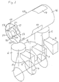
- die Brennkraftmaschine nach Fig. 1 in Schrägansicht
- Fig. 3
- die Brennkraftmaschine nach Fig. 1 und 2 in einem Längsschnitt
- Fig. 1
- a three-cylinder two-stroke internal combustion engine in a cross section
- Fig. 2
- the internal combustion engine of FIG. 1 in an oblique view
- Fig. 3
- 1 and 2 in a longitudinal section
Die Brennkraftmaschinen nach Fig. 1 bis 3 weisen übliche, nicht als Kurbelkastenspülpumpengehäuse gestaltete Brennkraftmaschinengehäuse mit Maschinenzylindern und übliche Kurbeltriebe mit Kurbelwellen und Pleuelstangen und Hubkolben auf. Im Zylinderkopf ist dabei jeweils mindestens ein Drehkolbenlader angeordnet, welcher der Gasförderung dient und gleichzeitig den Gaseinlaß in den Brennraum steuert.The internal combustion engines according to FIGS. 1 to 3 have conventional internal combustion engine housings with engine cylinders, not designed as a crankcase purge pump housing, and conventional crank drives with crankshafts and connecting rods and reciprocating pistons. At least one rotary piston loader is arranged in the cylinder head, which is used for gas production serves and controls the gas inlet into the combustion chamber at the same time.
Bei dem Ausführungsbeispiel nach Fig. 1 bis 3 weist eine Zweitaktbrennkraftmaschine 1 ein Maschinengehäuse 2 mit drei in Reihe angeordneten Maschinenzylindern 3 mit Wasserkühlung, eine Kurbelwelle 4, Pleuelstangen 5 und Hubkolben 6 auf. Die Maschinenzylinder 3 sind an den unteren Enden der Brennräume 7 mit von den Hubkolben 6 gesteuerten Auslaßschlitzen 8 und sich zumindest annähernd quer zu den Maschinenzylinderachsen erstreckenden seitlichen Abgaskanälen 9 versehen.In the exemplary embodiment according to FIGS. 1 to 3, a two-stroke
Auf den Maschinenzylindern 3 ist ein Zylinderkopf 10 angeordnet, der an den Kühlwasserkreislauf der Maschinenzylinder 3 angeschlossen ist. Der Zylinderkopf 10 bildet das feststehende Ladergehäuse 11 eines sich über alle drei Maschinenzylinder 3 in deren Reihenanordnungsrichtung hinweg erstreckenden für alle drei Maschinenzylinder 3 gemeinsamen Drehkolbenladers 12. In der Mantelwand des Ladergehäuses 11 ist im wesentlichen auf der von den Maschinenzylindern 3 abgewandten Seite eine zumindest annähernd radiale Ladereinlaßöffnung 13 (Fig. 1) vorgesehen, die sich annähernd über die gesamte Länge des Ladergehäuses 11 erstreckt. Die Ladereinlaßöffnung 13 ist mit ihrer Einströmseite an einen sich in Laderlängsrichtung erstreckenden Frischgaskanal angeschlossen, in dem eine um die Kanallängsachse schwenkbar gelagerte Steuerhülse angeordnet ist, die ein radiales Fenster aufweist und der Füllungsregelung dient. Ferner sind in der Mantelwand des Ladergehäuses 11 in dem den Maschinenzylindern 3 zugewandten Bereich in die Brennräume 7 mündende Laderauslaßöffnungen 14 vorgesehen. Innerhalb des Ladergehäuses 11 sind zwei exzentrisch zueinander-ineinander angeordnete zahnradartige Drehkolben angeordnet, die gleichsinnig, jedoch mit unterschiedlichen Winkelgeschwindigkeiten umlaufen können. Der eine der beiden Drehkolben ist an der Außenseite zylindrisch ausgebildet und bildet einen Außenläufer 15 mit einem Außenläufermantel 16 und drei gleichmäßig über den Umfang verteilt angeordneten Außenläufer-Eingriffsteilen 17, zwischen denen drei einander gleiche Verdichtungskammern 18 gebildet sind. Diese erstrecken sich ohne Querschotten über die gesamte Länge des Außenläufers 15 und sind über ihre gesamte Länge radial nach innen offen, nach außen jedoch durch den Außenläufermantel 16 weitgehend geschlossen. Die drei Verdichtungskammern 18, deren Volumen auf das der Brennräume 7 abgestimmt ist, sind jeweils einem der drei Maschinenzylinder 3 zugeordnet und lediglich im Bereich des Zuordnungszylinders durch ein Fenster 19 in dem Außenläufermantel 16 radial nach außen offen. Die drei Fenster 19 sind demgemäß in axialer Richtung des Drehkolbenladers 12 mit Abstand voneinander und in Umfangsrichtung um jeweils 120° gegeneinander versetzt angeordnet. In axialer Richtung des Drehkolbenladers 12 weisen die Fenster 19 jeweils eine Länge auf, die zumindest annähernd der lichten Weite der Laderauslaßöffnungen 14 gleich ist. Der andere der beiden Drehkolben ist in dem Außenläufer 15 angeordnet und bildet einen Innenläufer 20 mit zwei Innenläufer-Eingriffsteilen 21. Diese können in die Verdichtungskammern 18 eingreifen und sind derart bemessen, daß ihre Außenseite jeweils in der äußeren Extremlage, die in Fig. 1 dargestellt ist, bis auf einen engen Spalt an die Innenseite des Außenläufermantels 16 heranreicht. Der Innenläufer 20 ist mit einem Wellenansatz 22 versehen, der dem Innenläufer 20 benachbart ein Zahnrad 23 mit Außenverzahnung und an seinem äußeren freien Ende ein Antriebszahnrad 24 ebenfalls mit Außenverzahnung jeweils drehfest trägt. Das Zahnrad 23 kämmt mit einem Zahnkranz 25 mit Innenverzahnung, der an dem Außenläufer 15 befestigt ist. Das Antriebszahnrad 24 steht über eine nicht dargestellte Kette mit der Kurbelwelle 4 der Brennkraftmaschine 1 in Antriebsverbindung. Neben dem Drehkolbenlader 12 trägt der Zylinderkopf 10 drei in die Brennräume 7 ragende Zündkerzen 26.A
Beim Betrieb der Brennkraftmaschine 1 wird der Drehkolbenlader 12 von der Kurbelwelle 4 aus über das Antriebszahnrad 24 derart angetrieben, daß die Kurbelwelle 4 und der Außenläufer 15 des Drehkolbenladers 12 mit gleicher Drehzahl umlaufen. Das dabei durch die Ladereinlaßöffnung 13 in radialer Richtung quer zu den Drehkolbenachsen in den Drehkolbenlader 12 strömende Frischgas, das Luft oder ein Kraftstoff-Luft-Gemisch sein kann, tritt durch das jeweils in der Einströmstellung befindliche Fenster 19 in dem Außenläufermantel 16 in die zugeordnete Verdichtungskammer 18 ein und wird in dem Drehkolbenlader 12 verdichtet und durch die Laderauslaßöffnungen 14, die auch Brennraumeinlaßöffnungen sind, in die Brennräume 7 geschoben.When the
Der Außenläufer 15 wirkt bei jedem der drei Maschinenzylinder 3 als Steuerorgan für die Brennraumeinlaßöffnung. Während des letzten Teils des Verdichtungstaktes und während des Arbeitstaktes schließt der Außenläufermantel 16 die Laderauslaßöffnung 14 ab. Zum Ende der Abwärtsbewegung des Hubkolbens 6 und zu Beginn von dessen Aufwärtsbewegung, während also die verbrannten Gase durch die Auslaßschlitze 8 und den Abgaskanal 9 aus dem Maschinenzylinder 3 entweichen, tritt die Verdichtungskammer 18, die diesem Maschinenzylinder 3 zugeordnet ist, durch ihr Fenster 19 und die zugeordnete Laderauslaßöffnung 14 mit dem Brennraum 7 in Verbindung und läßt Frischgas am zylinderkopfseitigen Ende des Brennraumes 7 in diesen strömen. Durch die derart bewirkte Gleichstromspülung wird ein guter Gasaustausch im Maschinenzylinder 3 erreicht. Bei dem weiteren Aufwärtshub des Hubkolbens 6 strömt weiter Frischgas in den Brennraum 7, in dem sich nach Schließen der Auslaßschlitze 8 während einer Nachladephase der Druck des Frischgases auf einen Wert erhöht, der deutlich über dem Umgebungsdruck liegt. Der Außenläufermantel 16 schließt die Laderauslaßöffnung 14 rechtzeitig ab, so daß das Gas weiter verdichtet und gezündet werden und ein neuer Arbeitstakt folgen kann.The
Wird dem Drehkolbenlader 12 nicht ein Kraftstoff-Luft-Gemisch, sondern Luft zugeführt, kann Kraftstoff in den Drehkolbenlader 12 eingespritzt werden. Hierzu reicht ein Kraftstoff-Einspritzventil aus, das an der Stirnseite des Drehkolbenladers 12 angeordnet ist und von den Stirnseiten der Verdichtungskammern 18 überfahren wird. Es können jedoch auch für jeden Maschinenzylinder 3 gesonderte Kraftstoff-Einspritzventile vorgesehen sein, die in radialer Anordnung jeweils durch das zugeordnete Fenster 19 in die Verdichtungskammern 18 einspritzen. Auch eine Direkteinspritzung in die Brennräume 7 ist möglich.If air is supplied to the
- 11
- ZweitaktbrennkraftmaschineTwo stroke internal combustion engine
- 22nd
- MaschinengehäuseMachine housing
- 33rd
- MaschinenzylinderMachine cylinder
- 44th
- Kurbelwellecrankshaft
- 55
- Pleuelstangeconnecting rod
- 66
- HubkolbenReciprocating piston
- 77
- BrennraumCombustion chamber
- 88th
- AuslaßschlitzOutlet slot
- 99
- AbgaskanalExhaust duct
- 1010th
- ZylinderkopfCylinder head
- 1111
- LadergehäuseCharger housing
- 1212th
- DrehkolbenladerRotary piston loader
- 1313
- LadereinlaßöffnungLoader inlet opening
- 1414
- LaderauslaßöffnungLoader outlet opening
- 1515
- AußenläuferOutrunner
- 1616
- AußenläufermantelOuter rotor jacket
- 1717th
- Außenläufer-EingriffsteilExternal rotor engagement part
- 1818th
- VerdichtungskammerCompression chamber
- 1919th
- Fensterwindow
- 2020th
- InnenläuferInternal runner
- 2121
- Innenläufer-EingriffsteilInternal rotor engagement part
- 2222
- WellenansatzShaft approach
- 2323
- Zahnradgear
- 2424th
- AntriebszahnradDrive gear
- 2525th
- ZahnkranzSprocket
- 2626
- Zündkerzespark plug
Claims (3)
- Multicylinder internal combustion engine (1) with at least one rotary piston charger (12) which is in constant driving connection with the engine crank shaft (4) and has a charger housing (11) that abuts on the engine cylinder, whose outlet opening (14) forms the combustion space inlet opening, which can be closed off by a gas exchange control element that is separate from the engine piston, forming a rotary valve and has two swivel mounted parts (15, 20) in the charger housing (11) of the rotary piston charger (12), which is part of the cylinder head whereby one of the swivel-mounted parts is cylindrical (15) and forms a compression-chamber wall (16) of the charger which is used as control element for the charger outlet opening (14) and also as the gas exchange control element, formed as a rotary valve in the course of which the cylindrical rotor (15) forms a stationary border surface of the combustion space when the gas exchange has ended,
characterized by the fact
that the internal combustion engine has three cylinders (3) or a multiple of three,
that the engine cylinder (3) is supplied whith exhaust ports (8) at the bottom which are controlled by the pistons,
that the outer rotor (15) has three outer rotor engagement pieces (17), which are proportionately distributed on the periphery of the outer rotor casing (16). - Internal combustion engine as per claim 1, characterized by the fact that separate rotary piston chargers are assigned to the rows of combustion spaces when there are several rows of combustion spaces.
- Internal combustion engine as per claim 1, characterized by the fact that several rotary piston chargers are arranged in a row, one behind the other.
Priority Applications (1)
| Application Number | Priority Date | Filing Date | Title |
|---|---|---|---|
| AT89906069T ATE103370T1 (en) | 1988-05-20 | 1989-05-19 | INTERNAL COMBUSTION ENGINE WITH AT LEAST ONE DISPLACEMENT-TYPE SUPERCHARGER. |
Applications Claiming Priority (2)
| Application Number | Priority Date | Filing Date | Title |
|---|---|---|---|
| DE3817318 | 1988-05-20 | ||
| DE3817318A DE3817318C2 (en) | 1988-05-20 | 1988-05-20 | Reciprocating internal combustion engine with at least one rotary piston supercharger type |
Publications (2)
| Publication Number | Publication Date |
|---|---|
| EP0420863A1 EP0420863A1 (en) | 1991-04-10 |
| EP0420863B1 true EP0420863B1 (en) | 1994-03-23 |
Family
ID=6354844
Family Applications (1)
| Application Number | Title | Priority Date | Filing Date |
|---|---|---|---|
| EP89906069A Expired - Lifetime EP0420863B1 (en) | 1988-05-20 | 1989-05-19 | Internal combustion engine with at least one charger of positive displacement design |
Country Status (5)
| Country | Link |
|---|---|
| US (1) | US5375581A (en) |
| EP (1) | EP0420863B1 (en) |
| JP (1) | JP2736391B2 (en) |
| DE (1) | DE3817318C2 (en) |
| WO (1) | WO1989011584A1 (en) |
Families Citing this family (12)
| Publication number | Priority date | Publication date | Assignee | Title |
|---|---|---|---|---|
| DE4003512A1 (en) * | 1990-02-06 | 1991-08-08 | Bayerische Motoren Werke Ag | Fuel mixture catalytic ignition system - comes into contact with mixture only at ignition point |
| DE4008268A1 (en) * | 1990-03-15 | 1991-09-19 | Dietrich Gerhard Ellsaesser | Rotary piston compressor with selective cylinder loading - has load chamber for each cylinder in four-cylinder engine with output thrust additionally enhanced by varying transmission |
| WO1992001146A1 (en) * | 1990-07-05 | 1992-01-23 | Dullaway Glen A | Pressure charged multi-cylinder 2-stroke engine |
| SE9901704L (en) * | 1999-05-11 | 2000-11-12 | Lysholm Techn Ab | Combustion engine with supercharger |
| US6282898B1 (en) | 1999-05-13 | 2001-09-04 | Alberto Solaroli | Operation of forced induction internal combustion engines |
| JP2001082160A (en) | 1999-09-09 | 2001-03-27 | Yamaha Motor Co Ltd | Engine having supercharger |
| US6546901B2 (en) * | 2000-08-07 | 2003-04-15 | William Delaplaine Green | Two cycle internal combustion engine |
| US6539715B2 (en) | 2000-12-18 | 2003-04-01 | Caterpillar Inc | Turbocharger swivel connector |
| US20040031459A1 (en) * | 2001-08-08 | 2004-02-19 | Green William Delaplaine | Two-cycle internal combustion engine |
| CN101503974B (en) * | 2008-07-08 | 2013-01-02 | 太原理工大学 | Optional fuel hybrid type engine |
| US8505504B2 (en) * | 2009-04-09 | 2013-08-13 | Louis A. Green | Two-stroke engine and related methods |
| DE102014209864A1 (en) * | 2014-05-23 | 2015-12-17 | Bayerische Motoren Werke Aktiengesellschaft | Load control element for a quantity-controlled internal combustion engine |
Citations (1)
| Publication number | Priority date | Publication date | Assignee | Title |
|---|---|---|---|---|
| GB403245A (en) * | 1933-02-23 | 1933-12-21 | Cyril Terence Delaney | Improvements in or relating to the supercharging of internal combustion engines |
Family Cites Families (8)
| Publication number | Priority date | Publication date | Assignee | Title |
|---|---|---|---|---|
| US1869787A (en) * | 1927-09-19 | 1932-08-02 | John T Trumble | Supercharger |
| DE1114059B (en) * | 1956-08-09 | 1961-09-21 | Beteiligungs & Patentverw Gmbh | Rotary piston flushing and charging blower for internal combustion engines |
| DE2222500A1 (en) * | 1972-05-08 | 1973-11-22 | Wankel Felix | ROTARY PISTON BLOWER |
| US4041837A (en) | 1976-03-05 | 1977-08-16 | Franz Weidlich | Induction and exhaust apparatus for piston machines |
| DE3000145A1 (en) * | 1980-01-04 | 1981-07-09 | Hermann 7033 Herrenberg Kempter | Supercharged four-stroke IC engine - has trochoidal rotary piston assembly with one half exhaust driven, and another acting as charging compressor |
| DE3219793A1 (en) * | 1981-05-29 | 1983-02-03 | Wankel Gmbh, 1000 Berlin | External-axis rotary piston compressor |
| BR8107901A (en) * | 1981-12-04 | 1983-08-30 | Roger Boyd Walker | DOSING PUMPS AND DISTRIBUTING TUBES TO SUPPLY EXPLOSION ENGINE CYLINDERS |
| CH664423A5 (en) * | 1984-06-12 | 1988-02-29 | Wankel Felix | INNER AXIS ROTARY PISTON. |
-
1988
- 1988-05-20 DE DE3817318A patent/DE3817318C2/en not_active Expired - Fee Related
-
1989
- 1989-05-19 EP EP89906069A patent/EP0420863B1/en not_active Expired - Lifetime
- 1989-05-19 US US07/640,401 patent/US5375581A/en not_active Expired - Fee Related
- 1989-05-19 JP JP1505486A patent/JP2736391B2/en not_active Expired - Lifetime
- 1989-05-19 WO PCT/EP1989/000554 patent/WO1989011584A1/en active IP Right Grant
Patent Citations (1)
| Publication number | Priority date | Publication date | Assignee | Title |
|---|---|---|---|---|
| GB403245A (en) * | 1933-02-23 | 1933-12-21 | Cyril Terence Delaney | Improvements in or relating to the supercharging of internal combustion engines |
Also Published As
| Publication number | Publication date |
|---|---|
| EP0420863A1 (en) | 1991-04-10 |
| JP2736391B2 (en) | 1998-04-02 |
| WO1989011584A1 (en) | 1989-11-30 |
| DE3817318C2 (en) | 1997-05-28 |
| DE3817318A1 (en) | 1989-11-23 |
| JPH03504995A (en) | 1991-10-31 |
| US5375581A (en) | 1994-12-27 |
Similar Documents
| Publication | Publication Date | Title |
|---|---|---|
| DE3937359A1 (en) | INTERNAL COMBUSTION ENGINE | |
| EP0420863B1 (en) | Internal combustion engine with at least one charger of positive displacement design | |
| EP0021170B1 (en) | Two-stroke internal combustion engine | |
| DE4191140C2 (en) | Rotary engine | |
| DE19602703A1 (en) | Twin=port, two=stroke, high=speed engine | |
| DE102011001551B4 (en) | Internal combustion engine with a rotatable about its axis rotor | |
| EP1355053B1 (en) | Rotary piston engine | |
| CH667132A5 (en) | TURNING PISTON SINGLE-STOCK COMBUSTION ENGINE. | |
| WO1995034749A1 (en) | Internal combustion engine | |
| EP0136565A2 (en) | Unit comprising a piston engine and a drive | |
| EP0250497B1 (en) | Two-stroke cycle engine | |
| EP3452704B1 (en) | Two stroke engine | |
| DE3804411A1 (en) | Centre axis rotary engine of the rotating piston type | |
| DE2519473A1 (en) | ROTATING MOTOR | |
| DE3514787C2 (en) | ||
| DE2439806C2 (en) | Air-compressing, self-igniting internal combustion engine | |
| DE2234077A1 (en) | COMBINED FOUR-STROKE COMBUSTION ENGINE | |
| DE3041405A1 (en) | Cam driven engine | |
| DE3205495A1 (en) | Internal combustion engine | |
| DE2751675C2 (en) | ||
| DE2928829C2 (en) | Loaders for internal combustion engines | |
| EP0394763A1 (en) | Internal combustion engine | |
| DE2100905A1 (en) | Ring gear rotary piston machine | |
| DE507255C (en) | Internal combustion engine with combustion chambers arranged in the control slide | |
| DE19514531A1 (en) | Rotary piston engine |
Legal Events
| Date | Code | Title | Description |
|---|---|---|---|
| PUAI | Public reference made under article 153(3) epc to a published international application that has entered the european phase |
Free format text: ORIGINAL CODE: 0009012 |
|
| 17P | Request for examination filed |
Effective date: 19901120 |
|
| AK | Designated contracting states |
Kind code of ref document: A1 Designated state(s): AT BE CH FR GB IT LI LU NL SE |
|
| 17Q | First examination report despatched |
Effective date: 19920414 |
|
| GRAA | (expected) grant |
Free format text: ORIGINAL CODE: 0009210 |
|
| AK | Designated contracting states |
Kind code of ref document: B1 Designated state(s): AT BE CH FR GB IT LI LU NL SE |
|
| PG25 | Lapsed in a contracting state [announced via postgrant information from national office to epo] |
Ref country code: SE Free format text: THE PATENT HAS BEEN ANNULLED BY A DECISION OF A NATIONAL AUTHORITY Effective date: 19940323 Ref country code: NL Effective date: 19940323 Ref country code: BE Effective date: 19940323 |
|
| REF | Corresponds to: |
Ref document number: 103370 Country of ref document: AT Date of ref document: 19940415 Kind code of ref document: T |
|
| PG25 | Lapsed in a contracting state [announced via postgrant information from national office to epo] |
Ref country code: AT Effective date: 19940519 |
|
| PG25 | Lapsed in a contracting state [announced via postgrant information from national office to epo] |
Ref country code: LU Free format text: LAPSE BECAUSE OF NON-PAYMENT OF DUE FEES Effective date: 19940531 Ref country code: LI Effective date: 19940531 Ref country code: CH Effective date: 19940531 |
|
| ITF | It: translation for a ep patent filed |
Owner name: JACOBACCI CASETTA & PERANI S.P.A. |
|
| ET | Fr: translation filed | ||
| GBT | Gb: translation of ep patent filed (gb section 77(6)(a)/1977) |
Effective date: 19940713 |
|
| NLV1 | Nl: lapsed or annulled due to failure to fulfill the requirements of art. 29p and 29m of the patents act | ||
| PLBE | No opposition filed within time limit |
Free format text: ORIGINAL CODE: 0009261 |
|
| STAA | Information on the status of an ep patent application or granted ep patent |
Free format text: STATUS: NO OPPOSITION FILED WITHIN TIME LIMIT |
|
| REG | Reference to a national code |
Ref country code: CH Ref legal event code: PL |
|
| 26N | No opposition filed | ||
| PGFP | Annual fee paid to national office [announced via postgrant information from national office to epo] |
Ref country code: FR Payment date: 19990517 Year of fee payment: 11 |
|
| PGFP | Annual fee paid to national office [announced via postgrant information from national office to epo] |
Ref country code: GB Payment date: 19990519 Year of fee payment: 11 |
|
| PG25 | Lapsed in a contracting state [announced via postgrant information from national office to epo] |
Ref country code: GB Free format text: LAPSE BECAUSE OF NON-PAYMENT OF DUE FEES Effective date: 20000519 |
|
| GBPC | Gb: european patent ceased through non-payment of renewal fee |
Effective date: 20000519 |
|
| PG25 | Lapsed in a contracting state [announced via postgrant information from national office to epo] |
Ref country code: FR Free format text: LAPSE BECAUSE OF NON-PAYMENT OF DUE FEES Effective date: 20010131 |
|
| REG | Reference to a national code |
Ref country code: FR Ref legal event code: ST |
|
| PG25 | Lapsed in a contracting state [announced via postgrant information from national office to epo] |
Ref country code: IT Free format text: LAPSE BECAUSE OF NON-PAYMENT OF DUE FEES Effective date: 20050519 |