EP0420071B1 - Method for compressive packing and apparatus for bundling an article to be packed - Google Patents
Method for compressive packing and apparatus for bundling an article to be packed Download PDFInfo
- Publication number
- EP0420071B1 EP0420071B1 EP90118222A EP90118222A EP0420071B1 EP 0420071 B1 EP0420071 B1 EP 0420071B1 EP 90118222 A EP90118222 A EP 90118222A EP 90118222 A EP90118222 A EP 90118222A EP 0420071 B1 EP0420071 B1 EP 0420071B1
- Authority
- EP
- European Patent Office
- Prior art keywords
- reinforcement
- article
- bundling
- reinforcements
- wrapping
- Prior art date
- Legal status (The legal status is an assumption and is not a legal conclusion. Google has not performed a legal analysis and makes no representation as to the accuracy of the status listed.)
- Expired - Lifetime
Links
Images


Classifications
-
- B—PERFORMING OPERATIONS; TRANSPORTING
- B65—CONVEYING; PACKING; STORING; HANDLING THIN OR FILAMENTARY MATERIAL
- B65B—MACHINES, APPARATUS OR DEVICES FOR, OR METHODS OF, PACKAGING ARTICLES OR MATERIALS; UNPACKING
- B65B27/00—Bundling particular articles presenting special problems using string, wire, or narrow tape or band; Baling fibrous material, e.g. peat, not otherwise provided for
- B65B27/12—Baling or bundling compressible fibrous material, e.g. peat
- B65B27/125—Baling or bundling compressible fibrous material, e.g. peat and wrapping or bagging
Definitions
- the present invention relates to a method for compressive packing, in which an article to be packed, which must avoid mixing of foreign matters, contamination and biting by bundling belts, such as tow for tobacco filter, sanitary cotton, etc. is packed continuously and automatically by adding a series of functions to a compressive packing apparatus, and also relates to an apparatus for bundling an article to be packed.
- EP-A- 0 029 977, GB-A- 1 922 046, and FR-A-724 456 relate to different baling methods applied in the art.
- a method of wrapping an article to be packed with a sheet of stuck type or laminated type consisting of a polypropylene Hessian cloth and a polyethylene sheet or with a kraft paper sheet having a polyethylene film lining, thereafter protecting the outside of the wrapped article with reinforcement members which are excellent in both rigidity and strength such as corrugated cardboard sheets or plastic sheets, and then bundling the articles with bands or wires, has been heretofore employed, but such steps of the method were carried out by handwork in the prior art.
- a method for producing a package bale consisting of the steps of compressively shaping the article to be packed from either direction or both directions of the upward and downward directions within a compressing box for shaping, whose upper and lower surfaces are opened and whose four side surfaces can be arbitrarily opened or closed, thereafter opening the four side surfaces of the compression box, preliminarily mounting upper and lower reinforcements to upper and lower press seats of the compression box by handwork, wrapping the articles to be packed by handwork by making use of upper and lower wrapping materials for directly wrapping the article to be packed, which wrapping material is placed between the reinforcement and the articles to be packed, thereafter attaching reinforcements consisting of 2 to 4 pieces for reinforcing four side surfaces of the article to be packed onto these side surfaces by handwork, subsequently bundling the reinforcements by handwork by means of a number of bundling belts
- Fig. 10 is a front view of a compressive packing machine in the prior art
- Fig. 11 is a cross-section view taken along line XI-XI in Fig. 10(a).
- Fig. 1 shows an outline of a series of packing works including the steps of wrapping, mounting of reinforcements and bundling by handwork by means of the above-described type of compressive packing machine (It is to be noted that Fig. 1 was originally prepared for explaining the present invention, and so, only the portions necessitated for explaining the method for compressive packing by handwork are explained here.)
- An article to be packed such as acetate tow is stored in an enclosure box 1 shown in Fig. 10 in the preceding step of the process, thereafter they are carried into the center of a compressive packing machine by transport means such as a conveyor not shown as shown in Fig. 10(a), and they are further positioned by means of a positioning device 2.
- reinforcements 5a and 5b such as corrugated cardboard sheets, kraft paper sheets or plastic sheets are mounted to an upper press seat 3 and a lower press seat 4 of the compressive packing machine jointly with wrapping materials 6a and 6b having flexibility such as a polypropylene Hessian cloth and a polyethylene sheet in combination as stuck or laminated together with retainer metals 7a and 7b, respectively, by handwork as will be described later.
- wrapping materials 6a and 6b having flexibility such as a polypropylene Hessian cloth and a polyethylene sheet in combination as stuck or laminated together with retainer metals 7a and 7b, respectively, by handwork as will be described later.
- the upper press seat 3 is present at the limit (illustrated) position of rising as accompanied by the above-described reinforcement 5a and wrapping material 6a.
- the lower press seat 4 is present in the proximity of the top level of a fixed frame 8 (the limit position of rising) as accompanied by the reinforcement 5b and wrapping material 6b, and large doors 10a and 10b and a small door 11 in a compressing box assembly 9 are in a closed state. It is to be noted that the state depicted by double-dot chain lines of the large doors 10a and 10b in Fig. 11 is an opened state.
- the enclosure box 1 is once lowered to a neutral position 13 by means of an enclosure box elevator 12 associated with the compressive packing machine, here a tow receiver 14 of the enclosure box 1 is opened by a tow receiver opening/closing device not shown at the bottom of the enclosure box and continuously it is lowered to a position overlapping with the top of the fixed frame 8 (the limit position of lowering).
- the lower press seat 4 is pulled down by means of a hydraulic cylinder 16 or the like while supporting tow 15 within the enclosure box 1 via the reinforcement 5b and the wrapping material 6b, and comes to a limit position 17 of lowering. Consequently, the tow 15 within the enclosure box 1, which is an article to be packed, is transferred into the compressing box 9 with a part thereof left within the enclosure box 1.
- the upper press seat 3 is lowered by means of a hydraulic cylinder 18 or the like as accompanied by the reinforcement 5a and the wrapping material 6a and compressively shapes the tow 15 within the enclosure box 1 and the compressing box 9 into the compressing box 9 up to a predetermined height with a predetermined compressing force. Subsequently, at the above-described compressing height of the upper press seat 3, the large doors 10a and 10b and the small door 11 of the compressing box 9 are opened either manually or automatically. And thereafter, the works of wrapping of the tow with the wrapping materials, mounting of reinforcements and bundling are carried out.
- wrapping by the upper wrapping material 6a is carried out by handwork in such manner that the proximity of the upper edge of the lower wrapping material 6b may overlap with the upper wrapping material 6a.
- end portion treatments (folding) of the upper reinforcement 5a and the lower reinforcement 5b are carried out by handwork as shown at (d).
- the ears to be folded of the respective reinforcements are denoted by 74a, 74b and 75a, 75b, respectively.
- a treatment of passing bundling belts 20 such as bands (or wires) by making use of band-(or wire-)passing grooves 3a of the upper press seat 3 shown in Fig.
- band-(or wire-)passing treatment and joining treatment for the opposite end surfaces are carried out by handwork by making use of passing grooves (not shown) perpendicular to the band-(or wire-)passing grooves 3a and 4a provided in the upper press seat 3 in Fig. 10(b) and the lower press seat 4 in Fig. 10(c).
- the tow block is released from the compressed condition (the upper press seat 3 rises), and expands up to a constrained condition by the bands (or wires).
- the opposite end portions 90a and 90b of the side surface reinforcements 19a and 19b are treated (folded) by handwork as shown at (h), successively the reinforcements are bundled by bands 22, and a compressively packed bale is completed.
- a reinforcement 5b and a packing material 6b are manually mounted onto the lower press seat 4 and they are fixed to the lower press seat 4 by means of a retainer metal 7b as shown in Fig. 10(b).
- the hydraulic cylinder 18 is actuated, hence its ram is lowered, and the upper press seat 3 descends to a level convenient for mounting the upper reinforcement 5a and the upper wrapping material 6a, and stops there.
- the reinforcement 5a and the wrapping material 6a are mounted to the upper press seat 3 by handwork in a similar manner to that described above, and they are fixed by means of a retainer metal 7a.
- the upper press seat 3 is pulled up as accompanied by the reinforcement 5a and the wrapping material 6a by means of the hydraulic cylinder 18, and the machine is restored to the state shown in Fig. 10(a).
- the bottom tow receiver 14 of the emptied enclosure box 1 is closed, the enclosure box 1 is raised up to the upper limit level by means of the elevator 12, the positioning device is opened, the enclosure box 1 is transported to the outside of the compressive packing machine by means of a conveyor device not shown, and one cycle is finished.
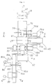
- reference numeral 101 generally designates a bundling apparatus, which is composed of a head side 102 and a guide side 103 opposed to each other, and the head side 102 is placed on a movable frame 105 which can be traversed by a cylinder 104.
- a table 107 which is made to advance or retreat by a cylinder 106, on the table 107 a plurality of bundling belt guides 108a are fixed to a frame 115 jointly with a bundling machine 110, and this bundling machine 110 (including the guides 108a) is provided so as to be able to traverse as driven by an electric motor cylinder 109.
- reference numeral 102′ in Fig. 19 designates a traversing standby position of the head side 102.
- a bale take-out conveyor 112 so as to be able to advance and retreat as driven by a cylinder 114, and as described above it is also possible to traverse.
- a plurality of bundling belt guides 108b are disposed in juxtaposition on a frame 119, this frame 119 is disposed on a table 118 which can advance and retreat on a frame 116 as driven by a cylinder 117, and on this frame 119 are provided bale push-out pushers 120a and 120b.
- the bundling machine 110 and the bundling belt guide 108a of the head side 102 of the bundling apparatus 101 are made to advance to position 108a′ and stop there, while the bundling belt guide 108b of the guide side 103 are made to advance to position 108b′, and bundling belts 125 such as bands are payed out from the bundling machine 110.
- the bundling belts 125 would make one turn around the article 123 to be packed as guided by the bundling belt guide 108a, the bundling belt passing grooves 124 in the upper press seat 122a, the bundling belt guide 108b and the bundling belt passing grooves 124 in the lower press seat 122b, and they fasten and bundle the article 123 to be packed. More particularly, for each of the bundling belt guides disposed in juxtaposition, sequentially the bundling machine 110 advances, retreats and traverses by necessary amounts to apply the bundling belts 125 one by one and to proceed bundling.
- the head side of the bundling apparatus 101 returns to its original position, the bundling machine 110 moves to position B, the bale take-out conveyor 112 moves to position A as interlocked with the former, the conveyor begins to rotate, the article 123 to be packed which has been bundled by the cylinder 114 is pushed out by the cylinder 114 to a receiving position in the proximity of the conveyor, and the article 123 to be packed is loaded on the bale take-out conveyor 112 via a pushing member 126 by means of the bale push-out pushers 120a and 120b provided on the guide side 103.
- This conveyor 112 is once stopped, and further retreated by the cylinder 114 to return to its original position, and the article 123 to be packed taken out from the bundling machine is sent to the next step of the process.
- bands and wires serving as bundling materials it was necessary to preliminarily cut them into predetermined lengths and to store them, also since the wrapping work, and the mounting and bundling works of the side surface reinforcements 19a and 19b were handworks, there was a shortcoming that much labor of the workers was necessitated, and also 2 to 4 workers were necessitated, although the number depended upon experience of the workers.
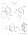
- Fig. 12 shows a procedure of packing of an article to be packed, and in this figure, at (a) is shown a state where wrapping materials 130 such as sheets and reinforcements 131a and 131b for the upper and lower surfaces were applied, at (b) is shown a state where side surface reinforcements 132 were applied, and at (c) is shown a state where a bundling belt 125 was applied only one. It is to be noted that illustration by chain lines at (c) represents that the article is bundled sequentially with bundling belts 125. At (d) is shown an appearance of a bundled package.
- Another object of the present invention is to provide an improved apparatus for bundling an article to be packed in which the above-described problems in the prior art are resolved.
- the subclaims relate to preferred embodiments of the method/apparatus.
- the reinforcement automatic mounting devices perform advancing operation to be pushed out towards the side surfaces of the article to be packed, the bundling belt guides would stop with a little gap clearance left from the upper press seat and the lower press seat, and also the side surface reinforcements are urged against the side surfaces of the article to be packed via reinforcement holders such as vacuum suction pads.
- the reinforcement holders such as vacuum suction pads release the reinforcements, the bundling apparatus and the reinforcement automatic mounting devices both retreat and return to their original positions.
- the head side and the guide side of the bundling apparatus as well as the reinforcement automatic mounting devices move to the reinforcement feeding position (position B in Fig. 16), and here, side surface reinforcements are automatically fed to the reinforcement holders of the reinforcement automatic mounting devices of both the head side and the guide side by means of the reinforcement feeding device.
- the bundling apparatus according to the present invention, automation of the application of side surface reinforcements to an article to be packed can be achieved, hence workers can be released from dangerous works, thereby improvements in safety and reduction of labor can be realized, and appearance of packed packages is stabilized without being influenced by skill of workers. Also, a cycle time can be shortened and improvements in a productivity can be achieved.
- Figs. 1 to 9 illustrate the first preferred embodiment of the present invention
- Fig. 1 shows the successive steps in the packing work according to the present invention, which are carried out as described previously
- Fig. 2 shows feed timings of wrapping materials, reinforcements and bundling materials to principal units upon practicing the packing work according to the present invention, and an outline of the system.
- the present invention has been proposed in order to resolve the problems caused by mixing of foreign matters from the outside due to damage of wrapping materials or contamination by these foreign matters from a sanitary view point, and further the problems caused by biting of bundling belts into wrapping materials and tow resulted from a repulsive force of tow forming an article to be packed as is the case with a compressively packed bale, especially a packed bale of acetate tow or the like for use as tobacco filters; and the present invention relates to a method for carrying out completely automatically a series of working steps of compressively shaping tow, which is an article to be packed, into a predetermined height, thereafter wrapping the article with flexible wrapping materials such as a stuck or laminated material of polypropylene Hessian cloth and a polyethylene sheet or a stuck material of a polyethylene sheet and a kraft paper sheet, then applying the so-called reinforcements having larger strength and rigidity than the above-mentioned wrapping material such as a corrugated cardboard sheet, a plastic sheet, a kraft
- Fig. 3 is a plan view showing a general layout of the apparatus used to practice the method according to the first preferred embodiment of the present invention
- Fig. 4 is a perspective view showing a portion X - X in Fig. 3.
- tow after tow has been stored in an enclosure box 1 in the preceding step of the process not shown, it is conveyed by conveyor means 51 to a center of a preliminary compression and transfer machine 52 in Fig. 3.
- the enclosure box 1 After the enclosure box 1 has been positioned at the center of the above-described tow transfer machine 52 by means of a positioning device not shown, it is lowered by an elevator 53, and further, a tow receiver 54 is opened in the illustrated manner by a tow receiver opening/closing device at the bottom of the enclosure box 1 not shown.
- a receiving seat 55 in Fig. 4 Prior to this operation, a receiving seat 55 in Fig. 4 is positioned at the top of a self-traveling type compression box 56 as penetrating therethrough. Accordingly, at the same time as "opening" completion of the tow receiver 54 at the bottom of the above-mentioned enclosure box 1, the tow 57 within the enclosure box 1 is transferred onto the receiving seat 55 via a fixed frame 58.
- the receiving seat 55 descends while supporting the tow 57, and it stops at a level somewhat higher than the tow receiver 58 at the bottom of the self-traveling type compression box 56 and holds this state.
- an upper press seat 59 descends and applies a pressure until the tow 57 within the enclosure box 1 is completely filled in the self-traveling type compression box 56.
- the receiving seat 55 descends and returns to the state shown in Fig. 6.
- the tow 57 within the self-traveling type compression box 56 is automatically transferred onto the tow receiver 58 associated with the self-traveling type compression box.
- the self-traveling type compression box 56 travels by itself along traveling rails 60a and 60b and comes to a main compression device 61, and here it is positioned at the center of the main compression device 61 by means of a positioning device not shown.
- the enclosure box 1 emptied at the center of the preliminary compression and tow transfer machine 52 is sent back to the installation of the preceding step by the conveyor device 51.
- the main compression device 61 is associated with an upper wrapping device 62 and a lower wrapping device 63, and before the above-mentioned self-traveling type compression box 56 enters the main compression device 61, the upper and lower reinforcements 5a and 5b and the upper and lower wrapping materials 6a and 6b have been automatically fed to these wrapping devices 62 and 63 (Ref. Fig. 1(a)).
- a reinforcement feed truck 67 travels by itself and comes right under the reinforcement lifting device 65, and here it receives the reinforcement 5a (the upper reinforcement) lifted up by the above-mentioned reinforcement lifting device 65.
- the reinforcement feed truck 67 comes to the center of the main compression device 61 while holding the upper reinforcement 5a and the lower reinforcement 5b, here it feeds the upper reinforcement 5a to the upper wrapping device 62 and the lower reinforcement 5b to the lower wrapping device 63, and thereafter it returns to the state shown in Fig. 7. Then, continuously the lower wrapping material 6b is fed to the lower wrapping device 63 and the upper wrapping material 6a is fed to the upper wrapping device 62 (Ref. Fig. 1(a)).
- the lower wrapping material 6b is drawn out from a wrapping material roll 68 by means of a drawing device 69, and after it has been cut into a length for one package, it is automatically fed to the lower wrapping device 63 by means of a wrapping material feeding device 70.
- the upper wrapping material 6a is drawn out from a wrapping material roll 71 by means of an upper wrapping material feeding device 72, and after it has been cut into a length for one package, it is fed to the upper wrapping device 62.
- the upper wrapping device 62 folds up the upper reinforcement 5a and the upper wrapping material 6a upwards as shown in Fig. 5 for the purpose of preparation for compressing tow within the self-traveling type compression box 56 in the next step of the process.
- FIG. 5 shows the state where the self-traveling type compression box 56 has come into the main compression device 61 and has been positioned under the above-described condition where the upper and lower reinforcements 5a and 5b and the upper and lower wrapping materials 6a and 6b were fed to the main compression device 61.
- the lower wrapping device 63 is raised by a hydraulic cylinder or the like up to the state where the lower wrapping material 6b closes the bottom of the self-traveling type compression box 56.
- the tow receiver 58 at the bottom of the self-traveling type compression box 56 is opened, and the tow is supported from the upper surface of a receiving seat 73 which forms one of constituent elements of the lower wrapping device 63, via the lower wrapping material 6b and the lower reinforcement 5b.
- an upper press seat 74 which forms one of constituent elements of the upper wrapping device 62 descends jointly with the upper reinforcement 5a and the upper wrapping material 6a, and compressively shapes the tow 57 within the self-traveling type compression box 56 with a predetermined compressing force up to a predetermined height.
- doors of the self-traveling type compression box 56 are automatically opened, and the self-traveling type compression box 56 travels by itself from the center of the main compression device 61 towards the preliminary compression and tow transfer device 52 and restores to its original state. Accordingly, in the preliminary compression and tow transfer device 52, transfer of tow from the subsequent enclosure box 1 to the self-traveling type compression box 56 is automatically carried out in succession as described previously.
- the tow 57 after completion of main compression is automatically wrapped by the lower wrapping device 63 and the upper wrapping device 62 in the sequence of wrapping of the lower portion and then wrapping of the upper portion as shown in Figs. 1(b) and 1(c), starting from the state shown in Fig. 6. It is to be noted that while the sequence of wrapping of the lower portion and then wrapping of the upper portion was chosen in the illustrated embodiment, in some cases the wrapping could be done through the prior art method in the sequence of wrapping of the upper portion and then wrapping of the lower portion.
- ears 74a, 74b, 75a and 75b of the upper and lower reinforcements 5a and 5b are folded in the illustrated manner by means of the upper wrapping device 62 and the lower wrapping device 63 (Ref. Fig. 1(d)). It is to be noted that these ears serve to prevent the bundling belts 20 such as bands, wires or the like from biting into the reinforcements.
- the side surface reinforcements 19a and 19b are stacked by a necessary number in stockers 76a and 76b, respectively, and they are automatically fed by reinforcement feeding devices 77a and 77b to a band (or wire) applying device 78 one by one when the band applying device 78 is present at a home position or standby position 78H, and to a band (or wire) guiding device 79 one by one when the band guiding device 79 is present at a home position or standby position 79H.
- the band (or wire) applying device 78 and the band (or wire) guiding device 79 would move automatically as accompanied by the side surface reinforcements 19a and 19b up to the positions of the band applying device 78 and the band guiding device 79 in Figs. 3 and 8, and further at the respective end points of movement they would move respectively towards the center of the main compression device 61 and would urge the side surface reinforcements 19a and 19b against the side surfaces of the tow block as shown in Fig. 1(e).
- bundling with bundling belts 20 such as bands or wires is carried out sequentially by the band (or wire) applying device 78 as shown in Fig. 1(f) by making use of band (or wire) guides provided within the upper press seat 74 associated with the upper wrapping device 62 and within the receiving seat 73 associated with the lower wrapping device 63.
- the band (or wire) applying device 78 returns to its standby position 78H shown in Fig. 3.
- a bale take-out conveyor 80 To the band (or wire) applying device 78 is interlocked a bale take-out conveyor 80, and accordingly, when the band (or wire) applying device 78 occupies the standby position 78H, as interlocked therewith the conveyor 80 advances up to the line connecting the preliminary compression and tow transfer device 52 and the center of the main compression device 61.
- the upper press seat 74 including the upper wrapping device 62 releases the compressing force applied to the tow block, and also it rises for the purpose of preparation for taking out the bale, which has completed a packing work up to the state shown in Fig. 1(f), from the main compression device 61 onto the bale take-out conveyor 80.
- the band (or wire) guiding device 79 is associated with a bale push-out machine 81.
- the bale take-out conveyor 80 advances towards the main compression device 61 in order to receive a bale.
- the packed bale is pushed out onto the bale take-out conveyor 80 by the bale push-out machine 81.
- the packed bale comes to the bundling machine 84, via the bale take-out conveyor 80, a traverser 82 and a bale transport conveyor 83.
- To the bundling machine 84 have been preliminarily fed end surface reinforcements 21a and 21b from end surface reinforcement stockers 85a and 85b by means of reinforcement feeding devices 86a and 86b, respectively, as shown in Fig. 1(g).
- the method for setting the bundling machine and the reinforcements is similar to that shown in Fig. 15.
- the ears of the upper and lower reinforcements 5a and 5b of the packed bale are folded by well-known folding guides and folding machines not shown in the midway of the transport by the bale transport conveyor 83, the ears of the upper reinforcement 5a being folded downwards, while those of the lower reinforcement 5b being folded upwards, and thus they are dealt with so that the ears may not become obstacles when the end surface reinforcements 21a and 21b are applied.
- the packed bale is conveyed by the bale transport conveyor 83 and comes to a horizontal bundling device 89.
- the ears of the reinforcements 19a and 19b (90a and 90b: there are two ears at the opposite ends of each reinforcement 19a or 19b) are folded as shown in Fig. 1(h) by means of a ear folding device assembled in the horizontal bundling device 89 but not shown, and subsequently, a bundling portion 91 of the bundling device 89 shown in Fig. 9 descends, and sequentially performs application of bands (or wires) 22 as shown in Fig. 1(i) to make the ears 90a and 90b of the reinforcements 19a and 19b butt against the end surfaces of the packed bale for confining them.
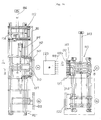
- reference numeral 133 designates a compressive packing machine main body, within this compressive packing machine main body 133, tow or the like is compressed by a cylinder 134 via an upper press seat 122a and a lower press seat 122b to form an article 123 to be packed, and also it is automatically wrapped with a wrapping material 130 by means of a lower wrapping device 136 and an upper wrapping device 135. It is to be noted that to the upper and lower surfaces of the article 123 to be packed are mounted reinforcements 131a and 131b by the means described above in connection to the first preferred embodiment.
- the article 123 to be packed which was wrapped with the wrapping material 130 is bundled after bundling belts 125 have been applied thereto through a series of operations of a head side 102 and a guide side 103 of a bundling apparatus 101, which correspond to the band applying device 78 and the band guiding device 79, respectively, in the first preferred embodiment.
- the apparatus according to the second preferred embodiment of the present invention is characterized in that a reinforcement mounting device 137 for automatically mounting side surface reinforcements 132 prior to the bundling step, is additionally provided in the above-mentioned bundling apparatus 101.
- holding frames 138 are provided vertically on the opposite sides of the front portion of the upper surface of a table 107, mount members 139 of a reinforcement holding mechanism are mounted to the same frames 138 via slide mechanisms 140 consisting of guides and the like, in the same mount member 139 are disposed a plurality of (four, in the illustrated embodiment) reinforcement holders such as vacuum suction pads or the like (since the reinforcement could be held by acicular members, the holder should not be limited to a vacuum suction pad), the side surface reinforcement 132 such as a corrugated cardboard sheet is held by suction by means of the holder, and the mount member 139 is adapted to perform advancing and retreating operations so as not to interfere with the bundling belt guides 108a, as driven by cylinders 142.
- rails 146 are laid, a movable frame 105 is provided with rollers, and the same frame 105 is laterally movable along the rails 146 between position A
- a mount member 139 is mounted to a frame 119 via a slide mechanism 140, reinforcement holders such as vacuum suction pads 141 or the like are disposed so that they can advance and retreat as driven by a cylinder 142 in such manner that they may not interfere with bundling belt guides 108b similarly to the above-described.
- reinforcement holders such as vacuum suction pads 141 or the like are disposed so that they can advance and retreat as driven by a cylinder 142 in such manner that they may not interfere with bundling belt guides 108b similarly to the above-described.
- rails 144 are laid, the movable frame 105 is provided with rollers, so that the same frame 145 is laterally movable along the rails 144 between position A and position B as driven by a cylinder 143.
- the head side 102 is normally present at the standby position B, and under this condition, a reinforcement is fed to the reinforcement mounting device 137 by means of a reinforcement feeding device not shown. Then, the vacuum suction pads 141 advance as driven by the cylinder 142, receive the side surface reinforcement 132 from the reinforcement feeding device by sucking it, and retreat, and under this condition they stand by. Likewise, the guide side 103 is also normally present at the standby position B, and under this condition, a reinforcement is fed to the reinforcement mounting device 137 by means of a reinforcement feeding device not shown. At this time, the vacuum suction pads 141 advance as driven by the cylinder 142, receive the side surface reinforcement 132 from the reinforcement feeding device by sucking it, and retreat, and under this condition they stand by.
- the head side 102 moves jointly with the movable frame 105 as driven by the cylinder 104, further it moves up to position A via the table 107 as driven by the cylinder 106, also the guide side 103 moves jointly with the movable frame 145 as driven by the cylinder 143, further it moves up to position A via the table 118 as driven by the cylinder 117, and they push out the bundling belt guides 108a and 108b up to the positions 108a′ and 108b′ where small gap clearances are left between these guides and the upper and lower press seats 122a and 122b, respectively. Since the vacuum suction pads 141 holding the side surface reinforcements 132 also advance as a result of this operation, the side surface reinforcements 132 are also automatically urged against the side surfaces of the article 132 to be packed.
- the bundling machine 110 advances a little, thereafter it moves laterally up to the next bundling belt guide position, and advances a little to continue bundling.
- the article 132 is bundled sequentially by the bundling belts 125 one by one.
- the vacuum suction pads 141 of the both sides release the vacuum pressure. (It is to be noted that the vacuum pressure could be released immediately after the side surface reinforcements 132 have been urged against the article 123 to be packed.)
- the head side 102 retreats as driven by the cylinder 106, the bale take-out conveyor 112 is moved up to position A via the movable frame 105 by the cylinder 104, then the head side 102 moves to position B as interlocked, and receives feed of the side surface reinforcement 132 in the above-described manner.
- the bale take-out conveyor 112 is pushed out against the side surface of the packed article after bundling (completed bale) via the table 113 by the cylinder 114, the completed bale is pushed out by the bale push-out pusher 120a and 120b provided in the guide side 103, and is taken out while being loaded on the above-mentioned conveyor 112.
- the guide side 103 moves up to position B via the movable frame 145 as driven by the cylinder 143, and receives feeding of the side surface reinforcement 132. Subsequently, similar operations are automatically repeated.
- the method for compressive packing according to the present invention since the method for compressive packing according to the present invention has the characteristic feature, there is no need to preliminarily combine a reinforcement and a wrapping material set by set as is the case with the prior art method, hence human labor saving can be achieved, and also it is unnecessary to reserve a space for temporary storage. Also, according to the present invention, since a compressive packing work is carried out automatically, persons can be released from a simple labor of the packing work and also released from a dangerous work, and moreover, a productivity can be improved by shortening a total cycle time necessitated for packing of one package.
- the bundling apparatus according to the present invention is used for practicing the novel compressive packing method, since the apparatus is constructed as described above in detail, automation of the application of side surface reinforcements to an article to be packed can be achieved, hence workers can be released from dangerous works, thereby improvements in safety and reduction of labor can be achieved, and appearance of packed packages is stabilized without being influenced by skill of workers. Also, a cycle time can be shortened and improvements in a productivity can be achieved.
Description
- The present invention relates to a method for compressive packing, in which an article to be packed, which must avoid mixing of foreign matters, contamination and biting by bundling belts, such as tow for tobacco filter, sanitary cotton, etc. is packed continuously and automatically by adding a series of functions to a compressive packing apparatus, and also relates to an apparatus for bundling an article to be packed.
- EP-A- 0 029 977, GB-A- 1 922 046, and FR-A-724 456 relate to different baling methods applied in the art.
- In a package bale of a compressively packed article having a small bulk density and a large repulsive force such as chemical fibers, natural fibers and the like, for the purpose of preventing contamination of a packed article, mixing of foreign matters and the like caused by biting by bundling belts due to repulsive forces after compressive packing or breakdown of packing materials, a method of wrapping an article to be packed with a sheet of stuck type or laminated type consisting of a polypropylene Hessian cloth and a polyethylene sheet or with a kraft paper sheet having a polyethylene film lining, thereafter protecting the outside of the wrapped article with reinforcement members which are excellent in both rigidity and strength such as corrugated cardboard sheets or plastic sheets, and then bundling the articles with bands or wires, has been heretofore employed, but such steps of the method were carried out by handwork in the prior art.
- Heretofore, in a packing work of an article to be packed which has a small bulk density and which must avoid mixing of foreign matters and generation of contamination such as tow (synthesized fibers) for tobacco filter, a method for producing a package bale consisting of the steps of compressively shaping the article to be packed from either direction or both directions of the upward and downward directions within a compressing box for shaping, whose upper and lower surfaces are opened and whose four side surfaces can be arbitrarily opened or closed, thereafter opening the four side surfaces of the compression box, preliminarily mounting upper and lower reinforcements to upper and lower press seats of the compression box by handwork, wrapping the articles to be packed by handwork by making use of upper and lower wrapping materials for directly wrapping the article to be packed, which wrapping material is placed between the reinforcement and the articles to be packed, thereafter attaching reinforcements consisting of 2 to 4 pieces for reinforcing four side surfaces of the article to be packed onto these side surfaces by handwork, subsequently bundling the reinforcements by handwork by means of a number of bundling belts, and then releasing the compressive forces, has been employed.
- In the following, one example of a method for compressive packing in the prior art will be explained, by way of example, in connection to a method for packing tow made of acetate for use in tobacco filters with reference to Figs. 10 and 11. In these figures, Fig. 10 is a front view of a compressive packing machine in the prior art, and Fig. 11 is a cross-section view taken along line XI-XI in Fig. 10(a). In addition, Fig. 1 shows an outline of a series of packing works including the steps of wrapping, mounting of reinforcements and bundling by handwork by means of the above-described type of compressive packing machine (It is to be noted that Fig. 1 was originally prepared for explaining the present invention, and so, only the portions necessitated for explaining the method for compressive packing by handwork are explained here.)
- An article to be packed such as acetate tow is stored in an enclosure box 1 shown in Fig. 10 in the preceding step of the process, thereafter they are carried into the center of a compressive packing machine by transport means such as a conveyor not shown as shown in Fig. 10(a), and they are further positioned by means of a
positioning device 2. - On the other hand,
reinforcements upper press seat 3 and alower press seat 4 of the compressive packing machine jointly with wrappingmaterials upper press seat 3 is present at the limit (illustrated) position of rising as accompanied by the above-describedreinforcement 5a and wrappingmaterial 6a. Thelower press seat 4 is present in the proximity of the top level of a fixed frame 8 (the limit position of rising) as accompanied by thereinforcement 5b and wrappingmaterial 6b, andlarge doors 10a and 10b and asmall door 11 in acompressing box assembly 9 are in a closed state. It is to be noted that the state depicted by double-dot chain lines of thelarge doors 10a and 10b in Fig. 11 is an opened state. - Under the above-described state of the respective portions, the enclosure box 1 is once lowered to a
neutral position 13 by means of anenclosure box elevator 12 associated with the compressive packing machine, here atow receiver 14 of the enclosure box 1 is opened by a tow receiver opening/closing device not shown at the bottom of the enclosure box and continuously it is lowered to a position overlapping with the top of the fixed frame 8 (the limit position of lowering). Thelower press seat 4 is pulled down by means of ahydraulic cylinder 16 or the like while supportingtow 15 within the enclosure box 1 via thereinforcement 5b and the wrappingmaterial 6b, and comes to alimit position 17 of lowering. Consequently, thetow 15 within the enclosure box 1, which is an article to be packed, is transferred into thecompressing box 9 with a part thereof left within the enclosure box 1. - On the other hand, the
upper press seat 3 is lowered by means of ahydraulic cylinder 18 or the like as accompanied by thereinforcement 5a and the wrappingmaterial 6a and compressively shapes thetow 15 within the enclosure box 1 and the compressingbox 9 into the compressingbox 9 up to a predetermined height with a predetermined compressing force. Subsequently, at the above-described compressing height of theupper press seat 3, thelarge doors 10a and 10b and thesmall door 11 of the compressingbox 9 are opened either manually or automatically. And thereafter, the works of wrapping of the tow with the wrapping materials, mounting of reinforcements and bundling are carried out. - In the following, the above-described series of packing works by handwork will be explained with reference to Fig. 1. In the compressive packing machine, when the compressive shaping of the
tow 15, which is an article to be packed, within the compressingbox 9 up to the predetermined height with the predetermined compressing force was completed and thelarge doors 10a and 10b and thesmall door 11 have been opened, wrapping of the tow with the lower wrappingmaterial 6b is carried out by handwork under the compressed condition of the tow block (thereafter this condition is maintained until completion of the wrapping and bundling works) as shown at (b). - Subsequently, as shown at (c), wrapping by the upper wrapping
material 6a is carried out by handwork in such manner that the proximity of the upper edge of the lower wrappingmaterial 6b may overlap with the upper wrappingmaterial 6a. After completion of wrapping by the upper and lower wrappingmaterials upper reinforcement 5a and thelower reinforcement 5b are carried out by handwork as shown at (d). (The ears to be folded of the respective reinforcements are denoted by 74a, 74b and 75a, 75b, respectively.) Thereafter, as shown at (f), a treatment of passingbundling belts 20 such as bands (or wires) by making use of band-(or wire-)passing grooves 3a of theupper press seat 3 shown in Fig. 10(b) and band-(or wire-)passing grooves 4a of thelower press seat 4 shown in Fig. 10(c) and a treatment of bundling the opposite end surfaces are carried out. At this time, since thebundling belts 20 such as bands (or wires) loosely bundle the tow block (including the upper and lower wrapping materials),side surface reinforcements end surface reinforcements - Subsequently, band-(or wire-)passing treatment and joining treatment for the opposite end surfaces are carried out by handwork by making use of passing grooves (not shown) perpendicular to the band-(or wire-)passing grooves 3a and 4a provided in the
upper press seat 3 in Fig. 10(b) and thelower press seat 4 in Fig. 10(c). Then the tow block is released from the compressed condition (theupper press seat 3 rises), and expands up to a constrained condition by the bands (or wires). Thereafter, the opposite end portions 90a and 90b of theside surface reinforcements bands 22, and a compressively packed bale is completed. Next, when the bale has been taken out of the compressive packing machine either by handwork or by a bale take-out device not shown, areinforcement 5b and apacking material 6b are manually mounted onto thelower press seat 4 and they are fixed to thelower press seat 4 by means of a retainer metal 7b as shown in Fig. 10(b). - Successively, in response to the manipulation of a push-button not shown, the
hydraulic cylinder 18 is actuated, hence its ram is lowered, and theupper press seat 3 descends to a level convenient for mounting theupper reinforcement 5a and the upper wrappingmaterial 6a, and stops there. At this level of theupper press seat 3, thereinforcement 5a and the wrappingmaterial 6a are mounted to theupper press seat 3 by handwork in a similar manner to that described above, and they are fixed by means of a retainer metal 7a. - After the above-described handwork has been finished, in response to manipulation of a push-button not shown, the
upper press seat 3 is pulled up as accompanied by thereinforcement 5a and the wrappingmaterial 6a by means of thehydraulic cylinder 18, and the machine is restored to the state shown in Fig. 10(a). On the other hand, thebottom tow receiver 14 of the emptied enclosure box 1 is closed, the enclosure box 1 is raised up to the upper limit level by means of theelevator 12, the positioning device is opened, the enclosure box 1 is transported to the outside of the compressive packing machine by means of a conveyor device not shown, and one cycle is finished. - In addition, an outline of an apparatus for bundling an article to be packed in the prior art will be explained with reference to Figs. 18, 19 and 20. In these figures,
reference numeral 101 generally designates a bundling apparatus, which is composed of ahead side 102 and aguide side 103 opposed to each other, and thehead side 102 is placed on amovable frame 105 which can be traversed by acylinder 104. Also, there is a table 107 which is made to advance or retreat by acylinder 106, on the table 107 a plurality ofbundling belt guides 108a are fixed to aframe 115 jointly with abundling machine 110, and this bundling machine 110 (including theguides 108a) is provided so as to be able to traverse as driven by anelectric motor cylinder 109. It is to be noted thatreference numeral 102′ in Fig. 19 designates a traversing standby position of thehead side 102. - In addition, on the
movable frame 105 is placed a bale take-outconveyor 112 so as to be able to advance and retreat as driven by acylinder 114, and as described above it is also possible to traverse. Also on theguide side 103 opposed to thehead side 102 as described above, a plurality of bundling belt guides 108b are disposed in juxtaposition on aframe 119, thisframe 119 is disposed on a table 118 which can advance and retreat on aframe 116 as driven by acylinder 117, and on thisframe 119 are provided bale push-outpushers - Upon bundling an
article 123 to be packed, thebundling machine 110 and thebundling belt guide 108a of thehead side 102 of thebundling apparatus 101 are made to advance toposition 108a′ and stop there, while the bundling belt guide 108b of theguide side 103 are made to advance to position 108b′, andbundling belts 125 such as bands are payed out from thebundling machine 110. Then, thebundling belts 125 would make one turn around thearticle 123 to be packed as guided by thebundling belt guide 108a, the bundlingbelt passing grooves 124 in theupper press seat 122a, the bundling belt guide 108b and the bundlingbelt passing grooves 124 in thelower press seat 122b, and they fasten and bundle thearticle 123 to be packed. More particularly, for each of the bundling belt guides disposed in juxtaposition, sequentially thebundling machine 110 advances, retreats and traverses by necessary amounts to apply thebundling belts 125 one by one and to proceed bundling. - When the bundling by bands of the
article 123 to be packed has finished, the head side of thebundling apparatus 101 returns to its original position, thebundling machine 110 moves to position Ⓑ, the bale take-outconveyor 112 moves to position Ⓐ as interlocked with the former, the conveyor begins to rotate, thearticle 123 to be packed which has been bundled by thecylinder 114 is pushed out by thecylinder 114 to a receiving position in the proximity of the conveyor, and thearticle 123 to be packed is loaded on the bale take-outconveyor 112 via a pushingmember 126 by means of the bale push-outpushers guide side 103. Thisconveyor 112 is once stopped, and further retreated by thecylinder 114 to return to its original position, and thearticle 123 to be packed taken out from the bundling machine is sent to the next step of the process. - However, in the above-described type of packing method in the prior art, in order to shorten a cycle time and lighten worker's labor it is necessary to preliminarily assemble the
reinforcements packing materials reinforcement 5b and the wrappingmaterial 6b to thelower press seat 4 was not so much laborious, mounting of thereinforcement 5a and the wrappingmaterial 6a to theupper press seat 3 became a work with the worker's face turned upward, and moreover, the weight of these members amounted to several kilograms, so that the work necessitated considerable labor and feeling of fatigue of the worker was also large. - Furthermore, with regard to bands and wires serving as bundling materials, it was necessary to preliminarily cut them into predetermined lengths and to store them, also since the wrapping work, and the mounting and bundling works of the
side surface reinforcements - On the other hand, in the prior art, upon wrapping and bundling a compressively packed bale, an article to be packed having a small bulk density and a large repulsive was wrapped with flexible wrapping material such as stuck material of polypropylene Hessian cloth and a polyethylene sheet and a polyethylene sheet or laminated material of these and the wrapped article was bundled with bundling belts either manually or automatically, but when the article had become a packed bale by releasing the compressive force, the bundling belts would bite into the packed bale due to a repulsive force of the article, furthermore, accompanying this biting, the wrapping material would be broken, and there occurred the problems of contamination of the packed article or mixing of foreign matters into the article. In addition, in the case where the packed article is unpacked again and is drawn out again continuously for use in the next step of the process, there was the problem that twining, entangling or the like would arise due to biting of the bundling belts into the fibers of the article. Because of these problems, bundling with bundling belts after application of reinforcements such as corrugated cardboard sheets to the outside of the wrapping sheet, had been carried out.
- Fig. 12 shows a procedure of packing of an article to be packed, and in this figure, at (a) is shown a state where wrapping
materials 130 such as sheets andreinforcements 131a and 131b for the upper and lower surfaces were applied, at (b) is shown a state whereside surface reinforcements 132 were applied, and at (c) is shown a state where abundling belt 125 was applied only one. It is to be noted that illustration by chain lines at (c) represents that the article is bundled sequentially withbundling belts 125. At (d) is shown an appearance of a bundled package. - It is to be noted that while the technique of wrapping with the wrapping
material 130 and automatic application of theupper surface reinforcement 131a and the lower surface reinforcement 131b has been already proposed, with regard to application of theside surface reinforcements 132, at the present after completion of bundling by means of a bundling machine, before release of a compressive force by a compressing machine in Fig. 13, thearticle 123 to be packed was held in contact with the inside of the side surface bundling belts by handworks of a plurality of workers as shown by arrow x in Fig. 20. However, since such works were carried out in the neighborhood of a large-sized press machine, and also within an operation range of a bundling machine, they involved an extremely large dangerous nature. In addition, since the other portions of the bundling apparatus were automated, there was a shortcoming that shortening of a cycle time could not be achieved because this portion serves as a neck. - It is therefore one object of the present invention to provide an improved method for compressive packing in which the above-described problems in the prior art are resolved.
- Another object of the present invention is to provide an improved apparatus for bundling an article to be packed in which the above-described problems in the prior art are resolved.
- The apparatus and the method are characterized by the features indicated in
claims 1 and 4. - The subclaims relate to preferred embodiments of the method/apparatus.
- In operation of the above-featured bundling apparatus, upon bundling at a bundling position (position Ⓐ in Fig. 16) equally on the head side and on the guide side of the bundling apparatus, the reinforcement automatic mounting devices perform advancing operation to be pushed out towards the side surfaces of the article to be packed, the bundling belt guides would stop with a little gap clearance left from the upper press seat and the lower press seat, and also the side surface reinforcements are urged against the side surfaces of the article to be packed via reinforcement holders such as vacuum suction pads. Here, if bundling by means of the bundling machine is finished, then the reinforcement holders such as vacuum suction pads release the reinforcements, the bundling apparatus and the reinforcement automatic mounting devices both retreat and return to their original positions. Thereafter, the head side and the guide side of the bundling apparatus as well as the reinforcement automatic mounting devices move to the reinforcement feeding position (position Ⓑ in Fig. 16), and here, side surface reinforcements are automatically fed to the reinforcement holders of the reinforcement automatic mounting devices of both the head side and the guide side by means of the reinforcement feeding device.
- According to the present invention, since there is no need to preliminarily combining a reinforcement and a wrapping material set by set as is the case with the prior art method, human labor saving can be achieved, and also it is unnecessary to reserve a space for temporary storage. Also according to the present invention, since a compressive packing work is carried out automatically, persons can be released from a simple labor of the packing work and also released from a dangerous work, and moreover, a productivity can be improved by shortening a total cycle time necessitated for packing of one package. Furthermore, if the bundling apparatus according to the present invention is used, automation of the application of side surface reinforcements to an article to be packed can be achieved, hence workers can be released from dangerous works, thereby improvements in safety and reduction of labor can be realized, and appearance of packed packages is stabilized without being influenced by skill of workers. Also, a cycle time can be shortened and improvements in a productivity can be achieved.
- The above-mentioned and other objects, features and advantages of the present invention will become more apparent by reference to the following description of preferred embodiments of the invention taken in conjunction with the accompanying drawings.
- In the accompanying drawings:
- Fig. 1 is a schematic view showing the successive steps in the method for compressive packing according to the present invention;
- Fig. 2 is a block diagram showing the method for compressive packing according to a first preferred embodiment of the present invention;
- Fig. 3 is a plan view of an apparatus for practicing the method according to the present invention;
- Fig. 4 is a perspective view taken along line X-X in Fig. 3 as viewed in the direction of arrows;
- Fig. 5 is a perspective view taken along line Y-Y in Fig. 3 as viewed in the direction of arrows;
- Fig. 6 is a perspective view showing the state where compression has completed starting from the state shown in Fig. 5;
- Fig. 7 is a cross-section view taken along line Z-Z in Fig. 3 as viewed in the direction of arrows;
- Fig. 8 is a cross-section view taken along line V-V in Fig. 3 as viewed in the direction of arrows;
- Fig. 9 is a cross-section view taken along line W-W in Fig. 3 as viewed in the direction of arrows;
- Fig. 10(a) is a front view of a compressive packing machine in the prior art;
- Figs. 10(b) and 10(c) are detailed views of essential parts in the machine shown in Fig. 10(a);
- Fig. 11 is a cross-section view taken along line XI-XI in Fig. 10(a) as viewed in the direction of arrows;
- Fig. 12 is a perspective view showing the successive steps in the wrapping operation by making use of a wrapping apparatus according to the present invention;
- Fig. 13 is a front view of an apparatus for bundling an article to be packed according to a second preferred embodiment of the present invention;
- Fig. 14 is a cross-section view taken along line A-A in Fig. 13 as viewed in the direction of arrows;
- Fig. 15 is a cross-section view taken along line B-B in Fig. 14 as viewed in the direction of arrows;
- Fig. 16 is a partial side view as viewed in the direction of an arrow C in Fig. 14;
- Fig. 17 is a partial side view as viewed in the direction of an arrow D in Fig. 14;
- Fig. 18 is a front view showing one example of a bundling apparatus in the prior art;
- Fig. 19 is a partial side view as viewed in the direction of an arrow E in Fig. 18; and
- Fig. 20 is a partial side view as viewed in the direction of an arrow F in Fig. 18.
- In the following, the first preferred embodiment of the present invention relating to a method for compressive packing is described. Figs. 1 to 9 illustrate the first preferred embodiment of the present invention, Fig. 1 shows the successive steps in the packing work according to the present invention, which are carried out as described previously, and Fig. 2 shows feed timings of wrapping materials, reinforcements and bundling materials to principal units upon practicing the packing work according to the present invention, and an outline of the system.
- Now, the present invention has been proposed in order to resolve the problems caused by mixing of foreign matters from the outside due to damage of wrapping materials or contamination by these foreign matters from a sanitary view point, and further the problems caused by biting of bundling belts into wrapping materials and tow resulted from a repulsive force of tow forming an article to be packed as is the case with a compressively packed bale, especially a packed bale of acetate tow or the like for use as tobacco filters; and the present invention relates to a method for carrying out completely automatically a series of working steps of compressively shaping tow, which is an article to be packed, into a predetermined height, thereafter wrapping the article with flexible wrapping materials such as a stuck or laminated material of polypropylene Hessian cloth and a polyethylene sheet or a stuck material of a polyethylene sheet and a kraft paper sheet, then applying the so-called reinforcements having larger strength and rigidity than the above-mentioned wrapping material such as a corrugated cardboard sheet, a plastic sheet, a kraft paper sheet and the like to all the outer surfaces of the wrapped article, and bundling them with bands, wires, etc.
- Fig. 3 is a plan view showing a general layout of the apparatus used to practice the method according to the first preferred embodiment of the present invention, and Fig. 4 is a perspective view showing a portion X - X in Fig. 3. In Fig. 4, after tow has been stored in an enclosure box 1 in the preceding step of the process not shown, it is conveyed by conveyor means 51 to a center of a preliminary compression and
transfer machine 52 in Fig. 3. Here, after the enclosure box 1 has been positioned at the center of the above-describedtow transfer machine 52 by means of a positioning device not shown, it is lowered by anelevator 53, and further, atow receiver 54 is opened in the illustrated manner by a tow receiver opening/closing device at the bottom of the enclosure box 1 not shown. Prior to this operation, a receivingseat 55 in Fig. 4 is positioned at the top of a self-travelingtype compression box 56 as penetrating therethrough. Accordingly, at the same time as "opening" completion of thetow receiver 54 at the bottom of the above-mentioned enclosure box 1, thetow 57 within the enclosure box 1 is transferred onto the receivingseat 55 via a fixedframe 58. Thereafter, the receivingseat 55 descends while supporting thetow 57, and it stops at a level somewhat higher than thetow receiver 58 at the bottom of the self-travelingtype compression box 56 and holds this state. Subsequently, anupper press seat 59 descends and applies a pressure until thetow 57 within the enclosure box 1 is completely filled in the self-travelingtype compression box 56. Next, when theupper press seat 59 again starts a rising operation, the receivingseat 55 descends and returns to the state shown in Fig. 6. - In the midway of descending of this receiving
seat 55, thetow 57 within the self-travelingtype compression box 56 is automatically transferred onto thetow receiver 58 associated with the self-traveling type compression box. When the transfer of the tow from the enclosure box 1 to the self-travelingtype compression box 56 has been completed, the self-travelingtype compression box 56 travels by itself along travelingrails 60a and 60b and comes to amain compression device 61, and here it is positioned at the center of themain compression device 61 by means of a positioning device not shown. On the other hand, the enclosure box 1 emptied at the center of the preliminary compression andtow transfer machine 52 is sent back to the installation of the preceding step by theconveyor device 51. In Fig. 7 showing a Z - Z cross-section in Fig. 3, and in Fig. 8 showing a V - V cross-section in Fig. 3, themain compression device 61 is associated with anupper wrapping device 62 and alower wrapping device 63, and before the above-mentioned self-travelingtype compression box 56 enters themain compression device 61, the upper andlower reinforcements lower wrapping materials wrapping devices 62 and 63 (Ref. Fig. 1(a)). - In the following, detailed description will be made on feeding of these members with reference to Figs. 3, 7, 8 and 1(a). At first, to the upper and
lower wrapping devices lower reinforcements lower reinforcements reinforcement stocker 64, above thestocker 64 is disposed areinforcement lifting device 65, and under thestocker 64 is disposed areinforcement elevator 66. At first, one of the reinforcements on thestocker 64 is lifted up by thereinforcement lifting device 65. Thereafter areinforcement feed truck 67 travels by itself and comes right under thereinforcement lifting device 65, and here it receives thereinforcement 5a (the upper reinforcement) lifted up by the above-mentionedreinforcement lifting device 65. Furthermore, it picks up onereinforcement 5b (the lower reinforcement). Thereafter thereinforcement feed truck 67 comes to the center of themain compression device 61 while holding theupper reinforcement 5a and thelower reinforcement 5b, here it feeds theupper reinforcement 5a to theupper wrapping device 62 and thelower reinforcement 5b to thelower wrapping device 63, and thereafter it returns to the state shown in Fig. 7. Then, continuously thelower wrapping material 6b is fed to thelower wrapping device 63 and theupper wrapping material 6a is fed to the upper wrapping device 62 (Ref. Fig. 1(a)). - As shown in Fig. 8, the
lower wrapping material 6b is drawn out from a wrappingmaterial roll 68 by means of adrawing device 69, and after it has been cut into a length for one package, it is automatically fed to thelower wrapping device 63 by means of a wrappingmaterial feeding device 70. On the other hand, theupper wrapping material 6a is drawn out from a wrappingmaterial roll 71 by means of an upper wrappingmaterial feeding device 72, and after it has been cut into a length for one package, it is fed to theupper wrapping device 62. Theupper wrapping device 62 folds up theupper reinforcement 5a and theupper wrapping material 6a upwards as shown in Fig. 5 for the purpose of preparation for compressing tow within the self-travelingtype compression box 56 in the next step of the process. Fig. 5 shows the state where the self-travelingtype compression box 56 has come into themain compression device 61 and has been positioned under the above-described condition where the upper andlower reinforcements lower wrapping materials main compression device 61. Starting from the state shown in Fig. 5, thelower wrapping device 63 is raised by a hydraulic cylinder or the like up to the state where thelower wrapping material 6b closes the bottom of the self-travelingtype compression box 56. - Next, the
tow receiver 58 at the bottom of the self-travelingtype compression box 56 is opened, and the tow is supported from the upper surface of a receivingseat 73 which forms one of constituent elements of thelower wrapping device 63, via thelower wrapping material 6b and thelower reinforcement 5b. Under this condition, an upper press seat 74 which forms one of constituent elements of theupper wrapping device 62, descends jointly with theupper reinforcement 5a and theupper wrapping material 6a, and compressively shapes thetow 57 within the self-travelingtype compression box 56 with a predetermined compressing force up to a predetermined height. Thereafter, doors of the self-travelingtype compression box 56 are automatically opened, and the self-travelingtype compression box 56 travels by itself from the center of themain compression device 61 towards the preliminary compression andtow transfer device 52 and restores to its original state. Accordingly, in the preliminary compression andtow transfer device 52, transfer of tow from the subsequent enclosure box 1 to the self-travelingtype compression box 56 is automatically carried out in succession as described previously. - On the other hand, the
tow 57 after completion of main compression is automatically wrapped by thelower wrapping device 63 and theupper wrapping device 62 in the sequence of wrapping of the lower portion and then wrapping of the upper portion as shown in Figs. 1(b) and 1(c), starting from the state shown in Fig. 6. It is to be noted that while the sequence of wrapping of the lower portion and then wrapping of the upper portion was chosen in the illustrated embodiment, in some cases the wrapping could be done through the prior art method in the sequence of wrapping of the upper portion and then wrapping of the lower portion. When the wrapping of a tow block with wrapping materials has completed, subsequentlyears lower reinforcements upper wrapping device 62 and the lower wrapping device 63 (Ref. Fig. 1(d)). It is to be noted that these ears serve to prevent thebundling belts 20 such as bands, wires or the like from biting into the reinforcements. - Next, description will be made on the steps of the process of starting from feeding of the
side surface reinforcements belts 20. - In Fig. 3, the
side surface reinforcements reinforcement feeding devices 77a and 77b to a band (or wire) applyingdevice 78 one by one when theband applying device 78 is present at a home position orstandby position 78H, and to a band (or wire) guidingdevice 79 one by one when theband guiding device 79 is present at a home position or standby position 79H. When the folding of ears of the upper andlower wrapping materials lower reinforcements device 78 and the band (or wire) guidingdevice 79 would move automatically as accompanied by theside surface reinforcements band applying device 78 and theband guiding device 79 in Figs. 3 and 8, and further at the respective end points of movement they would move respectively towards the center of themain compression device 61 and would urge theside surface reinforcements - Thereafter, through the well-known method, bundling with bundling
belts 20 such as bands or wires is carried out sequentially by the band (or wire) applyingdevice 78 as shown in Fig. 1(f) by making use of band (or wire) guides provided within the upper press seat 74 associated with theupper wrapping device 62 and within the receivingseat 73 associated with thelower wrapping device 63. When this bundling has been completed, the band (or wire) applyingdevice 78 returns to itsstandby position 78H shown in Fig. 3. To the band (or wire) applyingdevice 78 is interlocked a bale take-outconveyor 80, and accordingly, when the band (or wire) applyingdevice 78 occupies thestandby position 78H, as interlocked therewith theconveyor 80 advances up to the line connecting the preliminary compression andtow transfer device 52 and the center of themain compression device 61. - On the other hand, the upper press seat 74 including the
upper wrapping device 62 releases the compressing force applied to the tow block, and also it rises for the purpose of preparation for taking out the bale, which has completed a packing work up to the state shown in Fig. 1(f), from themain compression device 61 onto the bale take-outconveyor 80. In addition, the band (or wire) guidingdevice 79 is associated with a bale push-outmachine 81. - When the above-mentioned operation has been completed, the bale take-out
conveyor 80 advances towards themain compression device 61 in order to receive a bale. When the preparation for receiving a bale by the bale take-outconveyor 80 has been completed, the packed bale is pushed out onto the bale take-outconveyor 80 by the bale push-outmachine 81. - Thereafter, the packed bale comes to the bundling
machine 84, via the bale take-outconveyor 80, atraverser 82 and abale transport conveyor 83. To the bundlingmachine 84 have been preliminarily fedend surface reinforcements surface reinforcement stockers reinforcement feeding devices 86a and 86b, respectively, as shown in Fig. 1(g). The method for setting the bundling machine and the reinforcements is similar to that shown in Fig. 15. When the packed bale has been carried to the bundlingmachine 84 by thebale transport conveyor 83, positioning of the bale is effected by means of a bale positioning device not shown, and subsequently,end surface reinforcements end surface reinforcements lower reinforcements bale transport conveyor 83, the ears of theupper reinforcement 5a being folded downwards, while those of thelower reinforcement 5b being folded upwards, and thus they are dealt with so that the ears may not become obstacles when theend surface reinforcements bale transport conveyor 83 and comes to ahorizontal bundling device 89. - Here, the ears of the
reinforcements reinforcement horizontal bundling device 89 but not shown, and subsequently, a bundlingportion 91 of thebundling device 89 shown in Fig. 9 descends, and sequentially performs application of bands (or wires) 22 as shown in Fig. 1(i) to make the ears 90a and 90b of thereinforcements - Through the above-mentioned steps of operation, a series of packing works including wrapping by wrapping materials (inner packaging materials), application of reinforcements (outer packaging materials) and bundling of an article to be packed, which has a small bulk density and must be free from contamination, such as acetate tow, cotton mixed with staple fibers for sanitary use, and the like, are completed. It is to be noted that in connection to the
end surface reinforcements horizontal bundling machine 89 in Fig. 3 also could be omitted in the same manner. In addition, in the case of packed bales which do not necessitate theend surface reinforcements surface reinforcement stockers reinforcement feeding devices 86a and 86b, the bundlingmachine 84 and thehorizontal bundling device 89, packed bales satisfying this can be manufactured. - In the following, description will be made on a second preferred embodiment of the present invention relating to an apparatus for bundling an article to be packed, with reference to Figs. 13 to 17.
- At first, in Fig. 13,
reference numeral 133 designates a compressive packing machine main body, within this compressive packing machinemain body 133, tow or the like is compressed by acylinder 134 via anupper press seat 122a and alower press seat 122b to form anarticle 123 to be packed, and also it is automatically wrapped with a wrappingmaterial 130 by means of alower wrapping device 136 and anupper wrapping device 135. It is to be noted that to the upper and lower surfaces of thearticle 123 to be packed are mountedreinforcements 131a and 131b by the means described above in connection to the first preferred embodiment. And thearticle 123 to be packed which was wrapped with the wrappingmaterial 130, is bundled after bundlingbelts 125 have been applied thereto through a series of operations of ahead side 102 and aguide side 103 of abundling apparatus 101, which correspond to theband applying device 78 and theband guiding device 79, respectively, in the first preferred embodiment. - The apparatus according to the second preferred embodiment of the present invention is characterized in that a
reinforcement mounting device 137 for automatically mountingside surface reinforcements 132 prior to the bundling step, is additionally provided in the above-mentionedbundling apparatus 101. - In the
reinforcement mounting device 137, for thehead side 102 of thebundling apparatus 101, holdingframes 138 are provided vertically on the opposite sides of the front portion of the upper surface of a table 107,mount members 139 of a reinforcement holding mechanism are mounted to thesame frames 138 viaslide mechanisms 140 consisting of guides and the like, in thesame mount member 139 are disposed a plurality of (four, in the illustrated embodiment) reinforcement holders such as vacuum suction pads or the like (since the reinforcement could be held by acicular members, the holder should not be limited to a vacuum suction pad), theside surface reinforcement 132 such as a corrugated cardboard sheet is held by suction by means of the holder, and themount member 139 is adapted to perform advancing and retreating operations so as not to interfere with the bundlingbelt guides 108a, as driven bycylinders 142. In addition, rails 146 are laid, amovable frame 105 is provided with rollers, and thesame frame 105 is laterally movable along therails 146 between position Ⓐ and position Ⓑ as driven by acylinder 104. - Likewise, in the
guide side 103, amount member 139 is mounted to aframe 119 via aslide mechanism 140, reinforcement holders such asvacuum suction pads 141 or the like are disposed so that they can advance and retreat as driven by acylinder 142 in such manner that they may not interfere with bundling belt guides 108b similarly to the above-described. Furthermore, rails 144 are laid, themovable frame 105 is provided with rollers, so that thesame frame 145 is laterally movable along therails 144 between position Ⓐ and position Ⓑ as driven by acylinder 143. - Now, operation of the apparatus will be explained. In an apparatus for bundling an article to be packed which is provided with a reinforcement mounting capability, the
head side 102 is normally present at the standby position Ⓑ, and under this condition, a reinforcement is fed to thereinforcement mounting device 137 by means of a reinforcement feeding device not shown. Then, thevacuum suction pads 141 advance as driven by thecylinder 142, receive theside surface reinforcement 132 from the reinforcement feeding device by sucking it, and retreat, and under this condition they stand by. Likewise, theguide side 103 is also normally present at the standby position Ⓑ, and under this condition, a reinforcement is fed to thereinforcement mounting device 137 by means of a reinforcement feeding device not shown. At this time, thevacuum suction pads 141 advance as driven by thecylinder 142, receive theside surface reinforcement 132 from the reinforcement feeding device by sucking it, and retreat, and under this condition they stand by. - When the wrapping of the
article 123 to be packed was completed and the timing for mounting of a side surface reinforcement and bundling for thearticle 123 to be packed has come, thehead side 102 moves jointly with themovable frame 105 as driven by thecylinder 104, further it moves up to position Ⓐ via the table 107 as driven by thecylinder 106, also theguide side 103 moves jointly with themovable frame 145 as driven by thecylinder 143, further it moves up to position Ⓐ via the table 118 as driven by thecylinder 117, and they push out the bundlingbelt guides 108a and 108b up to thepositions 108a′ and 108b′ where small gap clearances are left between these guides and the upper andlower press seats vacuum suction pads 141 holding theside surface reinforcements 132 also advance as a result of this operation, theside surface reinforcements 132 are also automatically urged against the side surfaces of thearticle 132 to be packed. - When the bundling
machine 110 advanced a little, payed out abundling belt 125 and has bundled, thesame bundling machine 110 retreats a little, thereafter it moves laterally up to the next bundling belt guide position, and advances a little to continue bundling. In this way, thearticle 132 is bundled sequentially by the bundlingbelts 125 one by one. - When the bundling has been finished, the
vacuum suction pads 141 of the both sides release the vacuum pressure. (It is to be noted that the vacuum pressure could be released immediately after theside surface reinforcements 132 have been urged against thearticle 123 to be packed.) - Here, the
head side 102 retreats as driven by thecylinder 106, the bale take-outconveyor 112 is moved up to position Ⓐ via themovable frame 105 by thecylinder 104, then thehead side 102 moves to position Ⓑ as interlocked, and receives feed of theside surface reinforcement 132 in the above-described manner. In addition, the bale take-outconveyor 112 is pushed out against the side surface of the packed article after bundling (completed bale) via the table 113 by thecylinder 114, the completed bale is pushed out by the bale push-out pusher guide side 103, and is taken out while being loaded on the above-mentionedconveyor 112. Thereafter, theguide side 103 moves up to position Ⓑ via themovable frame 145 as driven by thecylinder 143, and receives feeding of theside surface reinforcement 132. Subsequently, similar operations are automatically repeated. - As will be obvious from the detailed description of the preferred embodiments above, since the method for compressive packing according to the present invention has the characteristic feature, there is no need to preliminarily combine a reinforcement and a wrapping material set by set as is the case with the prior art method, hence human labor saving can be achieved, and also it is unnecessary to reserve a space for temporary storage. Also, according to the present invention, since a compressive packing work is carried out automatically, persons can be released from a simple labor of the packing work and also released from a dangerous work, and moreover, a productivity can be improved by shortening a total cycle time necessitated for packing of one package. Furthermore, if the bundling apparatus according to the present invention is used for practicing the novel compressive packing method, since the apparatus is constructed as described above in detail, automation of the application of side surface reinforcements to an article to be packed can be achieved, hence workers can be released from dangerous works, thereby improvements in safety and reduction of labor can be achieved, and appearance of packed packages is stabilized without being influenced by skill of workers. Also, a cycle time can be shortened and improvements in a productivity can be achieved.
Claims (5)
- A method of compressively packing an article exhibiting a bulky tow-like state, said method comprising the following subsequent steps:
compressing a bulk portion of the article into a cubic or rectangular parallelepipedal shape;
subsequently automatically wrapping the shaped article from above and below with flexible wrapping materials;
automatically applying reinforcements to all of the surfaces of the article, including to the top and bottom surfaces of the article by providing upper and lower reinforcements in a reinforcement stacker, lifting one of the reinforcements stacked on said reinforcement stacker as an upper reinforcement by a reinforcement lifting device, transferring said upper reinforcement to a reinforcement feed truck moved under said upper reinforcement, picking up another one of said reinforcements as a lower reinforcement by said reinforcement feed truck and transferring the upper reinforcement and the lower reinforcement to the top and bottom of the article, respectively. - The method as claimed in claim 1, wherein said step of automatically applying the reinforcements comprises automatically applying side surface reinforcements to two opposed side surfaces of the article after the upper and lower reinforcements have been applied to the top and the bottom surfaces of the article, respectively, and automatically applying end surface reinforcements subsequently to the end surfaces of the article, said step of bundling including first wrapping bundling strips (20) around the top and bottom surfaces and the two opposed side surfaces of the article after the reinforcements have been applied thereto, and secondly wrapping bands around the end surfaces of the article after the end surface reinforcements have been applied thereto.
- The method as claimed in claim 1 or 2, wherein said step of automatically applying said reinforcements comprises applying the reinforcements having marginal portions which overhang the surfaces of the article so as to form ears extending beyond edges of the article at which the surfaces thereof intersect, and folding said ears toward the article prior to said step of bundling.
- An apparatus (101) for bundling an article (123) to be packed, for applying reinforcements (5a, 5b, 19a, 19b, 21a, 21b) to the article (123) and for facilitating the bundling of the article (123) over the reinforcements (5a, 5b, 19a, 19b, 21a, 21b, 132) with bundling belts (20, 22), said apparatus comprising:
a receiving seat (73) for supporting an article (123) to be reinforced and bundled;
a head side (78, 102) and a guide side portion (79, 103) of the apparatus disposed opposite one another across said receiving seat (73),
each of said head side and guide side portions (78, 102; 79,103) including bundling belt guides (108a, 108b) for guiding bundling belts (20) around an article (123) supported on said receiving seat (73), a reinforcement mounting device (137) having reinforcement holders for selectively holding and releasing a reinforcement (132), and cylinders (142) operatively connected to said reinforcement mounting device (137) for moving said reinforcement holders thereof toward and away from said receiving seat (73) independently of and in a non-interfering manner with respect to said bundling belt guides (108a, 108b); and
a reinforcement feeding device for automatically feeding reinforcements to each said reinforcement mounting device. - The apparatus as claimed in claim 4, wherein said reinforcement holders comprise a plurality of vacuum suction pads (141).
Applications Claiming Priority (4)
| Application Number | Priority Date | Filing Date | Title |
|---|---|---|---|
| JP25486489A JPH03124518A (en) | 1989-09-29 | 1989-09-29 | Method for compression-packing |
| JP254864/89 | 1989-09-29 | ||
| JP127915/89U | 1989-11-02 | ||
| JP1989127915U JP2516741Y2 (en) | 1989-11-02 | 1989-11-02 | Bundling device for objects to be packed |
Publications (2)
| Publication Number | Publication Date |
|---|---|
| EP0420071A1 EP0420071A1 (en) | 1991-04-03 |
| EP0420071B1 true EP0420071B1 (en) | 1994-06-08 |
Family
ID=26463744
Family Applications (1)
| Application Number | Title | Priority Date | Filing Date |
|---|---|---|---|
| EP90118222A Expired - Lifetime EP0420071B1 (en) | 1989-09-29 | 1990-09-21 | Method for compressive packing and apparatus for bundling an article to be packed |
Country Status (3)
| Country | Link |
|---|---|
| US (1) | US5131210A (en) |
| EP (1) | EP0420071B1 (en) |
| DE (1) | DE69009648T2 (en) |
Families Citing this family (22)
| Publication number | Priority date | Publication date | Assignee | Title |
|---|---|---|---|---|
| DE4015642A1 (en) * | 1990-05-15 | 1991-11-21 | Autefa Maschinenfab | METHOD AND DEVICE FOR TURNING A COVER FILM AROUND A PRESS BALE |
| US5224911A (en) * | 1992-01-17 | 1993-07-06 | Tien Pao Liem | Bale encasing and de-casing system |
| DE20104960U1 (en) * | 2001-03-21 | 2003-05-15 | Autefa Automation Gmbh | Packing unit for multi-section packing of compressed bales has packing unit for waist binding located in functioning sequence after packing unit for bottom and top packing and fixing device for compressed bales |
| ITFI20010135A1 (en) * | 2001-07-13 | 2003-01-13 | Gualchierani Textile Automatio | PRESS FOR THE FORMATION OF BALES OF TEXTILE MATERIAL OR OTHER, WITH COATING DEVICE USING A SHEET |
| US7306093B2 (en) | 2003-02-14 | 2007-12-11 | Eastman Chemical Company | Packages, packaging systems, methods for packaging and apparatus for packaging |
| US20050284775A1 (en) * | 2003-02-14 | 2005-12-29 | Mclaughlin Michael R | Packages, packaging systems, methods for packaging, and apparatuses for packaging |
| US20050121348A1 (en) * | 2003-12-09 | 2005-06-09 | Clare Timothy P. | Package insert and stackable package for articles |
| US7775351B2 (en) * | 2004-05-28 | 2010-08-17 | Hbi Branded Apparel Enterprises, Llc | System and method for packaging apparel |
| US7784399B2 (en) * | 2004-10-11 | 2010-08-31 | Paper And Plastic Partnership, Llc | Method and process of collecting, packaging and processing recyclable waste |
| US20090029074A1 (en) * | 2004-10-11 | 2009-01-29 | John Sasine | Method and process for collecting and processing recyclable waste |
| US20090148629A1 (en) * | 2005-06-24 | 2009-06-11 | Sasine John K | Systems, methods, and devices for collecting, packaging, and processing recyclable waste |
| US7520007B2 (en) * | 2004-11-10 | 2009-04-21 | Allen Medical Systems, Inc. | Accessory rail clamp with latch and lock mechanisms |
| US7730832B2 (en) * | 2005-04-28 | 2010-06-08 | Eastman Chemical Company | Method and apparatus for forming a bale having substantially flat upper and lower surfaces |
| US7540126B2 (en) * | 2006-04-19 | 2009-06-02 | Hbi Branded Apparel Enterprises, Llc | System and method for compactly packaging apparel |
| EP2910477B1 (en) * | 2014-02-21 | 2018-03-28 | Celanese Acetate LLC | Methods for packaging fibrous materials |
| EP3164333B1 (en) * | 2014-10-16 | 2017-08-30 | Neopost Technologies | System and method for automatically packaging items varying in size and number for shipment |
| US20180141700A1 (en) * | 2015-05-26 | 2018-05-24 | Sealed Air Corporation (Us) | Packaging Assembly |
| EP3284686B1 (en) * | 2016-08-16 | 2018-12-26 | Neopost Technologies | Device and method for assembling items for shipment |
| DE202017104766U1 (en) | 2017-08-09 | 2018-11-12 | Autefa Solutions Germany Gmbh | packaging device |
| DE202019105299U1 (en) | 2019-09-25 | 2021-01-08 | Autefa Solutions Germany Gmbh | Press bales, packaging equipment and production equipment for pressed bales |
| CN111891508A (en) * | 2020-07-13 | 2020-11-06 | 海盐通用机械塑料包装厂 | Fluffy product packer |
| CN114735270B (en) * | 2022-04-19 | 2023-07-28 | 青岛中城嘉业工程有限公司 | Reinforcing bar bundling and feeding device for building |
Citations (1)
| Publication number | Priority date | Publication date | Assignee | Title |
|---|---|---|---|---|
| EP0294820A1 (en) * | 1987-06-10 | 1988-12-14 | Autefa Maschinenfabrik Gmbh | Packaging method and apparatus for compressed bales |
Family Cites Families (12)
| Publication number | Priority date | Publication date | Assignee | Title |
|---|---|---|---|---|
| US1922046A (en) * | 1929-07-03 | 1933-08-15 | Brown Co | Bale covering and method of preparing same |
| FR724456A (en) * | 1931-09-03 | 1932-04-27 | Torfstreuverband Gmbh | Process for making and labeling peat bales |
| US3500609A (en) * | 1963-10-03 | 1970-03-17 | Signet Packaging Enterprises L | Means for packaging cuboid containers |
| US3962846A (en) * | 1974-01-28 | 1976-06-15 | Hardwicke-Etter Company | Apparatus for automatic wrapping of bales |
| DE2911958C2 (en) * | 1979-03-27 | 1993-10-07 | Hoechst Ag | Process for packaging fibrous material in bales and suitable press arrangement therefor |
| DE2948237A1 (en) * | 1979-11-30 | 1981-06-04 | Hoechst Ag, 6000 Frankfurt | METHOD AND DEVICE FOR PRESSING, PACKING AND STRAPPING FIBROUS GOODS IN BALE SHAPE |
| US4407107A (en) * | 1980-09-11 | 1983-10-04 | Hergeth, Incorporated | Horizontal baling apparatus and method |
| US4360997A (en) * | 1980-09-11 | 1982-11-30 | Hergeth, Incorporated | Baling apparatus and method |
| GB8613760D0 (en) * | 1986-06-06 | 1986-07-09 | Fiberglas Canada Inc | Packaging compressible items |
| DE3732376A1 (en) * | 1987-09-25 | 1989-04-06 | Fleissner Maschf Ag | METHOD FOR PACKAGING FIBROUS GOODS INTO BALES AND SUITABLE FIBER BALING PRESSES THEREFOR |
| DE3732390A1 (en) * | 1987-09-25 | 1989-04-06 | Fleissner Maschf Ag | FIBER BALE PRESS |
| US4805383A (en) * | 1988-01-11 | 1989-02-21 | Manville Corporation | Batt packaging machine and method |
-
1990
- 1990-09-21 EP EP90118222A patent/EP0420071B1/en not_active Expired - Lifetime
- 1990-09-21 DE DE69009648T patent/DE69009648T2/en not_active Expired - Fee Related
-
1991
- 1991-07-23 US US07/735,147 patent/US5131210A/en not_active Expired - Fee Related
Patent Citations (1)
| Publication number | Priority date | Publication date | Assignee | Title |
|---|---|---|---|---|
| EP0294820A1 (en) * | 1987-06-10 | 1988-12-14 | Autefa Maschinenfabrik Gmbh | Packaging method and apparatus for compressed bales |
Also Published As
| Publication number | Publication date |
|---|---|
| EP0420071A1 (en) | 1991-04-03 |
| DE69009648T2 (en) | 1994-11-17 |
| DE69009648D1 (en) | 1994-07-14 |
| US5131210A (en) | 1992-07-21 |
Similar Documents
| Publication | Publication Date | Title |
|---|---|---|
| EP0420071B1 (en) | Method for compressive packing and apparatus for bundling an article to be packed | |
| US4408438A (en) | Process and apparatus for pressing, packing and hooping fibrous material in bale form | |
| US4318264A (en) | Process and apparatus for the packaging of fibrous material in bales | |
| US6321512B1 (en) | Method of packaging a strip of material | |
| US4687462A (en) | Process for the automatic insertion of box-shaped bags | |
| CA1327519C (en) | Batt packaging machine | |
| EP2134608B1 (en) | Packaging device and packaging method | |
| EP0860356B1 (en) | Apparatus for placing groups of products on pallets | |
| EP2258618B1 (en) | Method and device for manufacturing a packaging unit | |
| JPH0613330B2 (en) | Pressing device for packing fibrous material into dust | |
| CN113787769A (en) | Automatic production line for flexible freight bags | |
| JP3522891B2 (en) | Apparatus for binding particularly compressible packages, such as a stack of corrugated paper | |
| CN110831862B (en) | Packaging apparatus and packaging method | |
| DE3437508A1 (en) | METHOD AND DEVICE FOR THE AUTOMATIC UNPACKING OF CAN LIDS OR THE LIKE ITEMS FROM PACKAGING | |
| GB2070550A (en) | Packaging loads with sheath coverings | |
| EP0695690B1 (en) | Method and apparatus for compressing and packaging fibrous materials in bales | |
| JPH03124518A (en) | Method for compression-packing | |
| JP2813874B2 (en) | Banding device | |
| EP0441753A1 (en) | Apparatus for the pressing and packing of bumps | |
| JP2516741Y2 (en) | Bundling device for objects to be packed | |
| JP2002166907A (en) | Drum winder in box-shaped packaging machine | |
| DE2135281A1 (en) | DEVICE FOR PACKAGING FLAT PACKS OF GOODS INTO BULK PACKAGES | |
| CN117208297A (en) | Efficient packaging system | |
| US20050217215A1 (en) | Horizontal strapping machine | |
| KR970010791B1 (en) | Packaging apparatus |
Legal Events
| Date | Code | Title | Description |
|---|---|---|---|
| PUAI | Public reference made under article 153(3) epc to a published international application that has entered the european phase |
Free format text: ORIGINAL CODE: 0009012 |
|
| 17P | Request for examination filed |
Effective date: 19901018 |
|
| AK | Designated contracting states |
Kind code of ref document: A1 Designated state(s): DE IT |
|
| 17Q | First examination report despatched |
Effective date: 19930202 |
|
| GRAA | (expected) grant |
Free format text: ORIGINAL CODE: 0009210 |
|
| AK | Designated contracting states |
Kind code of ref document: B1 Designated state(s): DE IT |
|
| REF | Corresponds to: |
Ref document number: 69009648 Country of ref document: DE Date of ref document: 19940714 |
|
| ITF | It: translation for a ep patent filed |
Owner name: FUMERO BREVETTI S.N.C. |
|
| PLBE | No opposition filed within time limit |
Free format text: ORIGINAL CODE: 0009261 |
|
| STAA | Information on the status of an ep patent application or granted ep patent |
Free format text: STATUS: NO OPPOSITION FILED WITHIN TIME LIMIT |
|
| 26N | No opposition filed | ||
| PGFP | Annual fee paid to national office [announced via postgrant information from national office to epo] |
Ref country code: DE Payment date: 19950928 Year of fee payment: 6 |
|
| PG25 | Lapsed in a contracting state [announced via postgrant information from national office to epo] |
Ref country code: DE Effective date: 19970603 |
|
| PG25 | Lapsed in a contracting state [announced via postgrant information from national office to epo] |
Ref country code: IT Free format text: LAPSE BECAUSE OF NON-PAYMENT OF DUE FEES;WARNING: LAPSES OF ITALIAN PATENTS WITH EFFECTIVE DATE BEFORE 2007 MAY HAVE OCCURRED AT ANY TIME BEFORE 2007. THE CORRECT EFFECTIVE DATE MAY BE DIFFERENT FROM THE ONE RECORDED. Effective date: 20050921 |