EP0419722A1 - Heating or conditioning installation for the ventilation of a motor vehicle passenger compartment - Google Patents
Heating or conditioning installation for the ventilation of a motor vehicle passenger compartment Download PDFInfo
- Publication number
- EP0419722A1 EP0419722A1 EP89118081A EP89118081A EP0419722A1 EP 0419722 A1 EP0419722 A1 EP 0419722A1 EP 89118081 A EP89118081 A EP 89118081A EP 89118081 A EP89118081 A EP 89118081A EP 0419722 A1 EP0419722 A1 EP 0419722A1
- Authority
- EP
- European Patent Office
- Prior art keywords
- air
- outlet openings
- heating
- air outlet
- passenger compartment
- Prior art date
- Legal status (The legal status is an assumption and is not a legal conclusion. Google has not performed a legal analysis and makes no representation as to the accuracy of the status listed.)
- Granted
Links
Images
Classifications
-
- B—PERFORMING OPERATIONS; TRANSPORTING
- B60—VEHICLES IN GENERAL
- B60H—ARRANGEMENTS OF HEATING, COOLING, VENTILATING OR OTHER AIR-TREATING DEVICES SPECIALLY ADAPTED FOR PASSENGER OR GOODS SPACES OF VEHICLES
- B60H1/00—Heating, cooling or ventilating [HVAC] devices
- B60H1/00642—Control systems or circuits; Control members or indication devices for heating, cooling or ventilating devices
- B60H1/00735—Control systems or circuits characterised by their input, i.e. by the detection, measurement or calculation of particular conditions, e.g. signal treatment, dynamic models
- B60H1/00742—Control systems or circuits characterised by their input, i.e. by the detection, measurement or calculation of particular conditions, e.g. signal treatment, dynamic models by detection of the vehicle occupants' presence; by detection of conditions relating to the body of occupants, e.g. using radiant heat detectors
Definitions
- the invention relates to a heating or air conditioning system for ventilation of the passenger compartment of a motor vehicle according to the preamble of claim 1;
- a ventilation system is known from DE-A1-37 30 466.
- the nozzles in the center plane (dashboard) of the vehicle especially in cooling mode for direct flow of the car occupants cool air. It is also known, in addition to the nozzles in the median plane, if appropriate, also to provide side nozzles in the rear part of the passenger compartment and / or a nozzle arranged in the region of the cardan tunnel in the rear compartment for targeted cooling of the passengers seated behind.
- the preferably electronic control device are in a closed loop according to a predetermined program depending on an operating unit in the dashboard predetermined temperature setpoints on the one hand and of different temperature sensors, esp. Of temperature sensors for the outside air, for the inside air and for the exhaust air from a Among other things, the blower speed of an air-conveying blower and thus the air volume, air distribution flaps and thus the air distribution in center plane or footwell or defrost and a mixed air damper in a mixed with cold and / or warm air mixed space and thus the air temperature automatically set; during the heating or cooling operation, in particular at high target actual temperature difference, it may come in the passenger compartment to certain passengers uncomfortable drafts, if by the control, for example, the air outlet openings of the median plane (dashboard) are acted upon and the fan speed for possible rapid adjustment of the actual internal temperature increases to the predetermined target internal temperature and / or the temperature of the air flow is additionally reduced. At certain passengers as uncomfortable perceived drafts may also occur if, for example, individual control setpoint input in the
- the inventive adjustment dependence of the control device of the seating positions respectively associated seat occupancy sensors can for large positive target-actual temperature differences, if, for example, only the driver is in the passenger compartment, advantageously provided without drafts for the driver anyway in terms of a maximum air flow Air distribution if necessary at the same time increased fan speed and relative to the driver position in terms of a fast target-actual comparison increased or decreased temperature over the rest, the unoccupied seating positions associated air outlet openings done, such that, for example, on the passenger side in addition the footwell air outlet openings and possibly existing rear room air outlet openings a higher air flow and elevated and lowered temperature are applied in comparison to the air outlet openings on the driver side; In order to achieve the fastest possible approximation of the actual internal temperature to the desired target internal temperature of the air volume flow on the driver's side must not be changed to an unpleasant level and possibly excessive temperatures.
- the air temperature in the passenger compartment of a motor vehicle in a closed loop according to predetermined setpoints, in particular one or more actual temperatures controlled and according to a predetermined by the electronic control program, inter alia, the respective temperature of the air outlet openings Exiting air streams, the fan speed and the air distribution flaps automatically adjusted.
- the input variables for the control circuit are the target values that can be predetermined by the vehicle occupant or persons to be actuated, as well as actual value signals from various sensors, especially temperature sensors for the outside air, for the inside air in the passenger compartment and for the blow-off air in the centric air ducts of the sensor air conditioner.
- a control unit BG on the dashboard of the vehicle each have a rotary switch for adjusting the fan speed and the desired interior temperature for the left vehicle interior side or for the right vehicle interior side and several buttons for adjusting the air distribution by hand and an automatic button to Switching to a single automatic air conditioning provided.
- the separately adjustable internal temperature for the left and the right passenger compartment side in automatic mode can be specified as the setpoint of a control device RV, which also has input values and the like on the input side.
- the sensors ST1; ST2; ST3; 4 detect at central air chamber locations the temperature of the respective total left or right or rear air flow, i. before dividing it e.g. in the sautaum- or middle or disc plane.
- the active part of the ventilation system also includes an air flow controller LM1 for the air outlet openings front left, an air flow controller LM2 for the air outlet openings front right and an air flow controller LM3 for the air outlet openings rear middle, also an air distribution plate LV1 for the air outlet openings front left, an air distribution plate LV2 for the air outlet openings 4 for the rear center air outlet openings and finally a temperature controller TS1 for the front left air outlet openings, a temperature controller TS2 for the front right air outlet openings and a temperature controller TS3; 4 for air outlet openings in the center of the center;
- a respective butterfly valve is provided for more or less wide opening of the center plane discharge nozzles D1 (front left), D2 (front right) and D3; 4 (rear center).
- pressure sensors SS1 to SS4 are provided according to an embodiment of the invention, either of the seating position occupying each pressure-actuated occupancy sensors or by the passengers by photocell interruption lichtbetätigbare occupancy sensors or automatically actuated at a Gurtbetutz occupancy sensors.
Abstract
Description
Die Erfindung bezieht sich auf eine Heiz- oder Klimaanlage zur Belüftung des Fahrgastraums eines Kraftfahrzeugs gemäß Oberbegriff des Anspruchs 1; eine derartige Belüftungsanlage ist aus der DE-A1-37 30 466 bekannt.The invention relates to a heating or air conditioning system for ventilation of the passenger compartment of a motor vehicle according to the preamble of claim 1; Such a ventilation system is known from DE-A1-37 30 466.
Bei der durch die DE-A1-37 30 466 bekannten Belüftungsanlage mit über eine Regelvorrichtung automatisch geregelter Lufttemperatur und angepaßter Luftmenge und Luftverteilung zum Fahrgastraum des Fahrzeuges dienen die Düsen in der Mittelebene (Armaturenbrett) des Fahrzeuges vor allem im Kühlbetrieb zur direkten Anströmung der Wageninsassen mit kühler Luft. Es ist auch bekannt, zusätzlich zu den Düsen in der Mittelebene gegebenenfalls noch Seitendüsen im hinteren Teil des Fahrgastraums und/oder eine im Bereich des Kardanwellentunnels im Fondraum angeordnete Düse zur gezielten Kühlung der hinten sitzenden Fahrgäste vorzusehen.In the ventilation system known from DE-A1-37 30 466 with automatically controlled via a control device air temperature and adjusted air volume and distribution to the passenger compartment of the vehicle, the nozzles in the center plane (dashboard) of the vehicle, especially in cooling mode for direct flow of the car occupants cool air. It is also known, in addition to the nozzles in the median plane, if appropriate, also to provide side nozzles in the rear part of the passenger compartment and / or a nozzle arranged in the region of the cardan tunnel in the rear compartment for targeted cooling of the passengers seated behind.
Von der vorzugsweise elektronischen Regelvorrichtung werden in einem geschlossenen Regelkreis gemäß einem vorgegebenen Programm abhängig von an einem Bediengerät im Armaturenbrett vorgebbaren Temperatur-Sollwerten einerseits und von verschiedenen Temperatursensoren, insbes. von Temperatur-Sensoren für die Außenluft, für die Innenluft sowie für die Ausblasluft aus einer zentralen Mischkammer des Klimagerätes abgegebenen Istwerten u.a. die Gebläsedrehzahl eines die Luft fördernden Gebläses und damit die Luftmenge, Luftverteilerklappen und damit die Luftverteilung in Mittelebene bzw. Fußraum bzw. Defrost sowie eine Mischluftklappe in einem mit Kalt- und/oder Warmluft beströmten Mischraums und damit die Lufttemperatur automatisch eingestellt; während des Aufheiz- bzw. Abkühlbetriebes, insbesondere bei großer Soll-Ist-Temperaturdifferenz, kann es im Fahrgastraum zu von bestimmten Fahrgästen als unangenehm empfundenen Zugerscheinungen kommen, wenn von der Regelung z.B. die Luftaustrittsöffnungen der Mittelebene (Armaturenbrett) beaufschlagt sind und die Gebläsedrehzahl zur möglichst schnellen Angleichung der Ist-Innentemperatur an die vorgegebene Soll-Innentemperatur erhöht und/oder die Temperatur des Luftstroms zusätzlich erniedrigt wird. Zu von bestimmten Fahrgästen als unkomfortabel empfundenen Zugerscheinungen kann es auch dann kommen, wenn bei z.B. individueller Regelungs-Sollwertvorgabe im linken bzw. rechten oder vorderen bzw. hinteren Fahrgastraum aufgrund einer vorherigen Fahrt eine Regelungseinstellung übernommen wird, die der unterschiedlichen nachfolgenden Besetzung des Fahrzeuges nicht optimal angepaßt ist.Of the preferably electronic control device are in a closed loop according to a predetermined program depending on an operating unit in the dashboard predetermined temperature setpoints on the one hand and of different temperature sensors, esp. Of temperature sensors for the outside air, for the inside air and for the exhaust air from a Among other things, the blower speed of an air-conveying blower and thus the air volume, air distribution flaps and thus the air distribution in center plane or footwell or defrost and a mixed air damper in a mixed with cold and / or warm air mixed space and thus the air temperature automatically set; during the heating or cooling operation, in particular at high target actual temperature difference, it may come in the passenger compartment to certain passengers uncomfortable drafts, if by the control, for example, the air outlet openings of the median plane (dashboard) are acted upon and the fan speed for possible rapid adjustment of the actual internal temperature increases to the predetermined target internal temperature and / or the temperature of the air flow is additionally reduced. At certain passengers as uncomfortable perceived drafts may also occur if, for example, individual control setpoint input in the left or right or front or rear passenger compartment due to a previous drive a control setting is adopted, the optimal default the different subsequent occupation of the vehicle is adapted.
Ausgehend von der vorher erläuterten Ursache für einen nicht von allen Fahrgästen als optimal empfundenen Belüftungskomfort, insbesondere bei hoher positiver Soll-Ist-Temperaturdifferenz und zu deren Ausregelung an sich vorteilhaftem maximalen Luftdurchsatz, können die von einzelnen Fahrgästen, vorzugsweise bei nicht voll besetztem Fahrgastraum, als störend empfundenen Zugerscheinungen trotz hohen Luftdurchsatzes mit einfachen Mitteln bei einer Belüftungsanlage der eingangs genannten Art durch die Lehre des Anspruchs 1 vermieden werden; vorteilhafte Ausgestaltungen dieser Lösung sind jeweils Gegenstand der Unteransprüche.Based on the previously explained cause of a not all passengers perceived as optimal ventilation comfort, especially at high positive target-actual temperature difference and their adjustment to advantageous maximum air flow, the individual passengers, preferably not fully occupied passenger compartment, as disturbing perceived drafts despite high air flow with simple means in a ventilation system of the type mentioned are avoided by the teaching of claim 1; advantageous embodiments of this solution are each the subject of the dependent claims.
Durch die erfindungsgemäße Einstellabhängigkeit der Regelvorrichtung von den Sitzpositionen jeweils zugeordneten Sitz-Belegungssensoren kann bei großen positiven Soll-Ist-Temperaturdifferenzen, wenn sich z.B. nur der Fahrer im Fahrgastraum befindet, in vorteilhafter Weise ohne Zugerscheinung für den Fahrer trotzdem eine im Sinne eines maximalen Luftdurchsatzes vorgesehene Luftverteilung bei gegebenenfalls gleichzeitig erhöhter Gebläsedrehzahl und gegenüber der Fahrerposition im Sinne eines schnellen Soll-Ist-Abgleichs erhöhter bzw. erniedrigter Temperatur über die übrigen, den nichtbelegten Sitzpositionen zugeordneten Luftaustrittsöffnungen erfolgen, derart daß z.B. auf der Beifahrerseite zusätzlich die Fußraum-Luftaustrittsöffnungen und evtl. vorhandenen Fondraum-Luftausstrittsöffnungen mit einem höheren Luftvolumenstrom und erhöhter bzw. erniedrigter Temperatur im Vergleich zu den Luftaustrittsöffnungen auf der Fahrerseite beaufschlagt sind; dabei muß zur Erzielung der möglichst schnellen Angleichung der Ist-Innentemperatur an die gewünschte Soll-Innentemperatur der Luftvolumenstrom auf der Fahrerseite nicht auf ein unangenehmes Maß und gegebenenfalls auf unangenehme Temperaturen überhöht verändert werden.Due to the inventive adjustment dependence of the control device of the seating positions respectively associated seat occupancy sensors can for large positive target-actual temperature differences, if, for example, only the driver is in the passenger compartment, advantageously provided without drafts for the driver anyway in terms of a maximum air flow Air distribution if necessary at the same time increased fan speed and relative to the driver position in terms of a fast target-actual comparison increased or decreased temperature over the rest, the unoccupied seating positions associated air outlet openings done, such that, for example, on the passenger side in addition the footwell air outlet openings and possibly existing rear room air outlet openings a higher air flow and elevated and lowered temperature are applied in comparison to the air outlet openings on the driver side; In order to achieve the fastest possible approximation of the actual internal temperature to the desired target internal temperature of the air volume flow on the driver's side must not be changed to an unpleasant level and possibly excessive temperatures.
Die Erfindung wird im folgenden anhand einer in der Zeichnung schematisch dargestellten Klimaanlage für ein Kraftfahrzeug näher erläutert.The invention is explained in more detail below with reference to an air conditioning system for a motor vehicle schematically illustrated in the drawing.
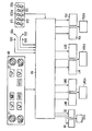
In einem automatisch, vorzugsweise elektronisch über eine Regelvorrichtung RV geregelten Klimagerät werden die Lufttemperatur im Fahrgastraum eines Kraftfahrzeuges in einem geschlossenen Regelkreis entsprechend vorgegebenen Sollwerten, insbesondere einer oder mehrerer Isttemperaturen geregelt und nach einem von der elektronischen Regelschaltung vorgegebenen Programm dazu u.a. die jeweilige Temperatur der durch Luftaustrittsöffnungen austretenden Luftströme, die Gebläsedrehzahl und die Luftverteilerklappen automatisch eingestellt. Als Eingangsgrößen für die Regelschaltung dienen die von dem oder den Fahrzeuginsassen über zu betätigende Einstellelemente vorgebbaren Sollwerte sowie Istwert-Signale von verschiedenen Sensoren, insbes. von Temperatur-Sensoren für die Außenluft, für die Innenluft im Fahrgastraum und für die Ausblasluft in den zentrischen Luftkanälen des Klimagerätes.In an automatic, preferably electronically controlled by a control device RV air conditioner, the air temperature in the passenger compartment of a motor vehicle in a closed loop according to predetermined setpoints, in particular one or more actual temperatures controlled and according to a predetermined by the electronic control program, inter alia, the respective temperature of the air outlet openings Exiting air streams, the fan speed and the air distribution flaps automatically adjusted. The input variables for the control circuit are the target values that can be predetermined by the vehicle occupant or persons to be actuated, as well as actual value signals from various sensors, especially temperature sensors for the outside air, for the inside air in the passenger compartment and for the blow-off air in the centric air ducts of the sensor air conditioner.
Im einzelnen sind an einem Bediengerät BG am Armaturenbrett des Fahrzeuges jeweils ein Drehschalter zur Einstellung der Gebläsedrehzahl bzw. der gewünschten Innentemperatur für die linke Fahrzeug-Innenraumseite bzw. für die rechte Fahrzeug-Innenraumseite sowie mehrere Tasten zur Einstellung der Luftverteilung von Hand und einer Automatiktaste zur Umschaltung auf eine allein automatische Klimatisierung vorgesehen. Die im Automatikbetrieb getrennt für die linke und die rechte Fahrgastraumseite jeweils einstellbare Innentemperatur ist als Sollwert einer Regelvorrichtung RV vorgebbar, die weiterhin eingangsseitig Istwerte u.a. von einem Sensor STI für die Innentemperatur, einem Sensor STA für die Außentemperatur, einem Sensor ST1 für die Ausblastemperatur der Luftaustrittsöffnungen vorn links, einem Sensor ST2 für die Ausblastemperatur der Luftaustrittsöffnungen vorn rechts und einem Sensor ST3;4 für die Ausblastemperatur der Luftaustrittsöffnungen hinten Mitte erhält. Die Sensoren ST1;ST2;ST3;4 erfassen dabei an zentralen Luftkammerstellen die Temperatur des jeweiligen gesamten linken bzw. rechten bzw. hinteren Luftstroms, d.h. vor dessen Aufteilung z.B. in die Fußtaum- bzw. Mittel- bzw. Scheibenebene.Specifically, on a control unit BG on the dashboard of the vehicle each have a rotary switch for adjusting the fan speed and the desired interior temperature for the left vehicle interior side or for the right vehicle interior side and several buttons for adjusting the air distribution by hand and an automatic button to Switching to a single automatic air conditioning provided. The separately adjustable internal temperature for the left and the right passenger compartment side in automatic mode can be specified as the setpoint of a control device RV, which also has input values and the like on the input side. from a sensor STI for the inside temperature, a sensor STA for the outside temperature, a sensor ST1 for the discharge temperature of the front left air outlet, a sensor ST2 for the discharge temperature of the right front air outlet and a sensor ST3, 4 for the discharge temperature of the rear air outlet , The sensors ST1; ST2; ST3; 4 detect at central air chamber locations the temperature of the respective total left or right or rear air flow, i. before dividing it e.g. in the Fußtaum- or middle or disc plane.
Zum aktiven Teil der Belüftungsanlage zählen weiterhin ein Luftmengensteller LM1 für die Luftaustrittsöffnungen vorn links, ein Luftmengensteller LM2 für die Luftaustrittsöffnungen vorn rechts sowie ein Luftmengensteller LM3 für die Luftaustrittsöffnungen hinten Mitte, weiterhin ein Luftverteilungssteller LV1 für die Luftaustrittsöffnungen vorn links, ein Luftverteilungssteller LV2 für die Luftaustrittsöffnungen vorn rechts sowie ein Luftverteilungssteller LV3;4 für die Luftaustrittsöffnungen hinten Mitte und schließlich ein Temperatursteller TS1 für die Luftaustrittsöffnungen vorn links, ein Temperatursteller TS2 für die Luftaustrittsöffnungen vorn rechts sowie ein Temperatursteller TS3;4 für die Luftaus trittsöffnungen hinten Mitte; zusätzlich ist in einer Override-Funktion jeweils eine Absperrklappe zur mehr oder weniger weiten Öffnung der Mittelebenen-Ausströmdüsen D1 (vorn links), D2 (vorn rechts) sowie D3;4 (hinten Mitte) vorgesehen.The active part of the ventilation system also includes an air flow controller LM1 for the air outlet openings front left, an air flow controller LM2 for the air outlet openings front right and an air flow controller LM3 for the air outlet openings rear middle, also an air distribution plate LV1 for the air outlet openings front left, an air distribution plate LV2 for the
Erfindungsgemäß werden im Automatikbetrieb von der Regelvorrichtung RV die Luftmengensteller LM1;LM2;LM3;4 bzw. die Luftverteilungssteller LV1;LV2;LV3;4 bzw. die Temperatursteller TS1;TS2;TS3;4 individuell im Sinne eines möglichst schnellen Luftdurchsatzes zur Erzielung der gewünschten Innentemperatur ohne Zugerscheinung für die besetzten Fahrsitzpositionen dadurch erreicht, daß der Regelvorrichtung RV durch Sitzsensoren SS1 für den Fahrersitz, SS2 für den Beifahrersitz, SS3 für den Fondsitz hinter dem Fahrer und SS4 für den Fondsitz hinter dem Beifahrer jeweils die belegten bzw. unbelegten Sitzpositionen als Istwert vorgegeben werden und eine Belüftungsregelung im Sinne eines maximalen Luftdurchsatzes bei dazu optimaler Luftverteilung über die den nichtbelegten Sitzposition zugeordneten Luftaustrittsöffnungen eingestellt wird.According to the invention, in automatic mode by the control device RV, the air flow controllers LM1; LM2; LM3; 4 or the air distribution actuators LV1; LV2; LV3; 4 or the temperature actuators TS1; TS2; TS3; 4 individually in the sense of the fastest possible air flow to achieve the desired Internal temperature without Zugerscheinung for the occupied driving position achieved in that the control device RV by seat sensors SS1 for the driver's seat, SS2 for the front passenger seat, SS3 for the rear seat behind the driver and SS4 for the rear seat behind the passenger each occupied or unoccupied seating positions as an actual value are specified and a ventilation control in the sense of a maximum air flow at optimal air distribution over the unoccupied seating position associated air outlet openings is set.
Als Drucksensoren SS1 bis SS4 sind nach einer Ausgestaltung der Erfindung entweder von den jeweils die Sitzposition einnehmenden Fahrgästen druckbetätigte Belegungssensoren oder von den Fahrgästen durch Lichtschranken-Unterbrechung lichtbetätigbare Belegungssensoren oder automatisch bei einer Gurtbetätigung ausgelöste Belegungssensoren vorgesehen.As pressure sensors SS1 to SS4 are provided according to an embodiment of the invention, either of the seating position occupying each pressure-actuated occupancy sensors or by the passengers by photocell interruption lichtbetätigbare occupancy sensors or automatically actuated at a Gurtbetätigung occupancy sensors.
Durch die Erfassung der Zahl und der Position der jeweils gerade im Fahrgastraum vorhandenen Fahrzeug-Insassen und der Belegungsauswertung durch die Elektronik können die jeweiligen Luftmengen- bzw. Luftverteilungs- bzw. Temperaturstellglieder für die Luftaustrittsöffnungen der nichtbesetzten Fahrzeugplätze in einem für eine möglichst schnelle Ausregelung optimalen Stellzustand gebracht werden und die Luftmengen- bzw. Luftverteilungs- bzw. Temperaturstellglieder der besetzten Sitzpositionen entsprechend den Sollvorgaben der Regelung und gegebenenfalls der in Override-Funktion vorgesehenen individuellen Einstellungen durch die Fahrzeug-Insassen im Sinne eine von Zug- und von unangenehmen Kälte-bzw. Wärmegefühlen freien Luftströmung eingestellt werden. Zweckmäßigerweise werden dabei noch bestehende Einstellungen für die nicht besetzten Sitzpositionen durch die Vorgabe der automatischen Regelung überspielt; dazu zählt insbesondere die automatische Öffnung einer gegebenenfalls noch geschlossenen Absperrklappe in einer Mittelebenen-Ausströmdüse D1 bzw.D2 bzw. D3;4 für eine zuvor belegte; jedoch nunmehr freie Sitzposition.By detecting the number and the position of each present in the passenger compartment vehicle occupants and the occupancy evaluation by the electronics, the respective Luftmengen- or Luftverteilungs- or temperature actuators for the air outlet openings of the unoccupied vehicle seats in an optimal for the fastest possible leveling control be brought and the air quantity or Luftverteilungs- or temperature actuators of the occupied seating positions according to the target specifications of the scheme and possibly provided in the override function individual settings by the vehicle occupants in the sense of a train and unpleasant cold or. Heat feelings free air flow can be adjusted. Expediently, existing settings for the unoccupied seating positions are transferred by specifying the automatic control; this includes, in particular, the automatic opening of an optionally still closed shut-off flap in a center-level discharge nozzle D1 or D2 or D3, 4 for a previously occupied one; but now free seating position.
Claims (7)
Priority Applications (3)
| Application Number | Priority Date | Filing Date | Title |
|---|---|---|---|
| DE8989118081T DE58903187D1 (en) | 1989-09-29 | 1989-09-29 | HEATING OR AIR CONDITIONING FOR VENTILATING THE PASSENGER ROOM OF A MOTOR VEHICLE. |
| EP19890118081 EP0419722B1 (en) | 1989-09-29 | 1989-09-29 | Heating or conditioning installation for the ventilation of a motor vehicle passenger compartment |
| ES89118081T ES2040959T3 (en) | 1989-09-29 | 1989-09-29 | INSTALLATION OF HEATING OR AIR CONDITIONING FOR VENTILATION OF THE PASSENGER COMPARTMENT OF AN AUTOMOBILE. |
Applications Claiming Priority (1)
| Application Number | Priority Date | Filing Date | Title |
|---|---|---|---|
| EP19890118081 EP0419722B1 (en) | 1989-09-29 | 1989-09-29 | Heating or conditioning installation for the ventilation of a motor vehicle passenger compartment |
Publications (2)
| Publication Number | Publication Date |
|---|---|
| EP0419722A1 true EP0419722A1 (en) | 1991-04-03 |
| EP0419722B1 EP0419722B1 (en) | 1992-12-30 |
Family
ID=8201957
Family Applications (1)
| Application Number | Title | Priority Date | Filing Date |
|---|---|---|---|
| EP19890118081 Expired - Lifetime EP0419722B1 (en) | 1989-09-29 | 1989-09-29 | Heating or conditioning installation for the ventilation of a motor vehicle passenger compartment |
Country Status (3)
| Country | Link |
|---|---|
| EP (1) | EP0419722B1 (en) |
| DE (1) | DE58903187D1 (en) |
| ES (1) | ES2040959T3 (en) |
Cited By (8)
| Publication number | Priority date | Publication date | Assignee | Title |
|---|---|---|---|---|
| FR2717747A1 (en) * | 1994-03-24 | 1995-09-29 | Valeo Thermique Habitacle | Heating and air-conditioning of automobile passenger compartment |
| EP0688689A1 (en) * | 1994-06-23 | 1995-12-27 | Daewoo Electronics Co., Ltd | Air conditioner for a vehicle |
| EP0873903A3 (en) * | 1997-04-24 | 1999-03-03 | Volkswagen Aktiengesellschaft | Sheet pressure sensor device for detecting vehicle seat occupancy |
| GB2340221A (en) * | 1998-07-29 | 2000-02-16 | Rover Group | Demisting a vehicle |
| EP1262346A2 (en) * | 2001-05-24 | 2002-12-04 | Ford Global Technologies, Inc. | An adaptive controller for an automotive climate control system |
| US6491577B2 (en) * | 2000-08-04 | 2002-12-10 | Denso Corporation | Air conditioning system for vehicle and method for controlling same |
| DE102016006663A1 (en) * | 2016-06-01 | 2017-12-07 | GM Global Technology Operations LLC (n. d. Ges. d. Staates Delaware) | Air conditioning system for a motor vehicle |
| DE102018214550A1 (en) * | 2018-08-28 | 2020-03-05 | Bayerische Motoren Werke Aktiengesellschaft | Fully variable and holistic ventilation flap control |
Families Citing this family (2)
| Publication number | Priority date | Publication date | Assignee | Title |
|---|---|---|---|---|
| DE10244992A1 (en) * | 2002-09-26 | 2004-04-01 | Conti Temic Microelectronic Gmbh | Space monitoring system, especially for monitoring a motor vehicle interior has at least one sensor so that, for example, sound playback, noise damping or climate control, can be matched to the number of occupants, |
| KR101673684B1 (en) * | 2014-10-28 | 2016-11-07 | 현대자동차주식회사 | Occupant detection apparatus and method for vehicle, and air conditining control method for vehicle using the same |
Citations (4)
| Publication number | Priority date | Publication date | Assignee | Title |
|---|---|---|---|---|
| US4434932A (en) * | 1981-07-07 | 1984-03-06 | Nippondenso Co., Ltd. | Air-conditioner control system for automobiles |
| US4537245A (en) * | 1981-10-09 | 1985-08-27 | Nippondenso Co., Ltd. | Zone air-conditioning control system for motor vehicle compartment |
| DE3730466A1 (en) * | 1987-09-08 | 1989-03-16 | Siemens Ag | Ventilation system for the passenger compartment of a motor vehicle |
| EP0272789B1 (en) * | 1986-12-22 | 1992-03-25 | Ford Motor Company Limited | Airconditioning control system for an automative vehicle |
-
1989
- 1989-09-29 ES ES89118081T patent/ES2040959T3/en not_active Expired - Lifetime
- 1989-09-29 EP EP19890118081 patent/EP0419722B1/en not_active Expired - Lifetime
- 1989-09-29 DE DE8989118081T patent/DE58903187D1/en not_active Expired - Lifetime
Patent Citations (4)
| Publication number | Priority date | Publication date | Assignee | Title |
|---|---|---|---|---|
| US4434932A (en) * | 1981-07-07 | 1984-03-06 | Nippondenso Co., Ltd. | Air-conditioner control system for automobiles |
| US4537245A (en) * | 1981-10-09 | 1985-08-27 | Nippondenso Co., Ltd. | Zone air-conditioning control system for motor vehicle compartment |
| EP0272789B1 (en) * | 1986-12-22 | 1992-03-25 | Ford Motor Company Limited | Airconditioning control system for an automative vehicle |
| DE3730466A1 (en) * | 1987-09-08 | 1989-03-16 | Siemens Ag | Ventilation system for the passenger compartment of a motor vehicle |
Non-Patent Citations (4)
| Title |
|---|
| PATENT ABSTRACTS OF JAPAN vol. 13, no. 6 (M-781)(3354) 09 Januar 1989, & JP-A-63 219414 (AISIN SEIKI CO. LTD.) 13 September 1988, * |
| PATENT ABSTRACTS OF JAPAN vol. 8, no. 234 (M-334)(1671) 26 Oktober 1984, & JP-A-59 114110 (NIPPON RADIATOR K.K.) 02 Juli 1984, * |
| PATENT ABSTRACTS OF JAPAN vol. 9, no. 206 (M-406)(1929) 23 August 1985, & JP-A-60 67213 (HITACHI SEISAKUSHO K.K.) 17 April 1985, * |
| PATENT ABSTRACTS OF JAPAN vol. 9, no. 34 (M-357)(1757) 14 Februar 1985, & JP-A-59 176109 (MATSUSHITA DENKI SANGYO K.K.) 05 Oktober 1984, * |
Cited By (13)
| Publication number | Priority date | Publication date | Assignee | Title |
|---|---|---|---|---|
| FR2717747A1 (en) * | 1994-03-24 | 1995-09-29 | Valeo Thermique Habitacle | Heating and air-conditioning of automobile passenger compartment |
| EP0688689A1 (en) * | 1994-06-23 | 1995-12-27 | Daewoo Electronics Co., Ltd | Air conditioner for a vehicle |
| WO1996000367A1 (en) * | 1994-06-23 | 1996-01-04 | Daewoo Electronics Co., Ltd. | Air conditioner for forming an air curtain |
| US5765635A (en) * | 1994-06-23 | 1998-06-16 | Daewoo Electronic Co., Ltd. | Air conditioner for forming an air curtain |
| EP0873903A3 (en) * | 1997-04-24 | 1999-03-03 | Volkswagen Aktiengesellschaft | Sheet pressure sensor device for detecting vehicle seat occupancy |
| GB2340221B (en) * | 1998-07-29 | 2002-02-13 | Rover Group | A vehicle |
| GB2340221A (en) * | 1998-07-29 | 2000-02-16 | Rover Group | Demisting a vehicle |
| US6491577B2 (en) * | 2000-08-04 | 2002-12-10 | Denso Corporation | Air conditioning system for vehicle and method for controlling same |
| EP1262346A2 (en) * | 2001-05-24 | 2002-12-04 | Ford Global Technologies, Inc. | An adaptive controller for an automotive climate control system |
| EP1262346A3 (en) * | 2001-05-24 | 2006-06-07 | Ford Global Technologies, Inc. | An adaptive controller for an automotive climate control system |
| DE102016006663A1 (en) * | 2016-06-01 | 2017-12-07 | GM Global Technology Operations LLC (n. d. Ges. d. Staates Delaware) | Air conditioning system for a motor vehicle |
| DE102018214550A1 (en) * | 2018-08-28 | 2020-03-05 | Bayerische Motoren Werke Aktiengesellschaft | Fully variable and holistic ventilation flap control |
| WO2020043364A1 (en) | 2018-08-28 | 2020-03-05 | Bayerische Motoren Werke Aktiengesellschaft | Fully variable and integral aeration flap controller |
Also Published As
| Publication number | Publication date |
|---|---|
| ES2040959T3 (en) | 1993-11-01 |
| EP0419722B1 (en) | 1992-12-30 |
| DE58903187D1 (en) | 1993-02-11 |
Similar Documents
| Publication | Publication Date | Title |
|---|---|---|
| EP1607254B1 (en) | Device for supplying air to the interior of a vehicle | |
| EP0825044B1 (en) | Method and device for controlling the mixing of air in a vehicle heating or air conditioning | |
| WO2005068232A1 (en) | Method for regulating air nozzles for air-conditioning a motor vehicle | |
| DE19910351A1 (en) | Motor vehicle air conditioning system with independent temperature control between left and right during maximum cooling | |
| DE19539001B4 (en) | air conditioning | |
| EP0419722B1 (en) | Heating or conditioning installation for the ventilation of a motor vehicle passenger compartment | |
| EP2036749B1 (en) | Air conditioning and ventilation system for a motor vehicle | |
| EP1216162A1 (en) | Vehicle air conditioning device | |
| EP0968858A1 (en) | Air supply and method for controlling air supply into a vehicle | |
| EP0568826B1 (en) | Process and air conditioning device to control the air conditioning in the first half and in the second half of the interior of a vehicle | |
| DE4143101C2 (en) | Air conditioning for a motor vehicle | |
| WO2020043364A1 (en) | Fully variable and integral aeration flap controller | |
| EP1422082B1 (en) | Control device for vehicle automatic air-conditioning system | |
| EP0419707B1 (en) | Heating or air conditioning apparatus, particularly for a motor vehicle, using air mixture temperature control | |
| DE10310022B4 (en) | Apparatus and method for air conditioning the rear seats in a vehicle | |
| EP0419704B1 (en) | Ventilation installation for a motor vehicle | |
| DE102009008414A1 (en) | Four zone air conditioning system controlling method for motor vehicle, involves maintaining maximal cooling capacity, maximal air-mass flow and/or direct supply of heated air for air conditioning zones in cooling operation | |
| DE19948735A1 (en) | Cooling method for automobile passenger seat evaluates signal from sunlight sensor for controlling cooling air stream fed through passenger seat | |
| EP0677408B1 (en) | Method for controlling and regulating of an automotive automatic air conditioning installation | |
| DE19811967B4 (en) | Method for controlling a heating or air conditioning system of a motor vehicle | |
| EP0771276B1 (en) | Air-conditioning device intended in particular for use in a motor vehicle, with atmosphere-side outlet temperature regulation | |
| EP0876930A2 (en) | Air conditioning device for the interior of a vehicle | |
| EP1327541B1 (en) | Air conditioning device for a vehicle | |
| DE3730466A1 (en) | Ventilation system for the passenger compartment of a motor vehicle | |
| DE10055670A1 (en) | Air conditioning and ventilation system for motor vehicle has air distribution chamber in connection to air conditioning unit with front/rear air channels, additional heating in rear channel |
Legal Events
| Date | Code | Title | Description |
|---|---|---|---|
| PUAI | Public reference made under article 153(3) epc to a published international application that has entered the european phase |
Free format text: ORIGINAL CODE: 0009012 |
|
| 17P | Request for examination filed |
Effective date: 19900807 |
|
| AK | Designated contracting states |
Kind code of ref document: A1 Designated state(s): DE ES FR IT |
|
| 17Q | First examination report despatched |
Effective date: 19920203 |
|
| GRAA | (expected) grant |
Free format text: ORIGINAL CODE: 0009210 |
|
| AK | Designated contracting states |
Kind code of ref document: B1 Designated state(s): DE ES FR IT |
|
| REF | Corresponds to: |
Ref document number: 58903187 Country of ref document: DE Date of ref document: 19930211 |
|
| ET | Fr: translation filed | ||
| ITF | It: translation for a ep patent filed |
Owner name: STUDIO JAUMANN |
|
| REG | Reference to a national code |
Ref country code: ES Ref legal event code: FG2A Ref document number: 2040959 Country of ref document: ES Kind code of ref document: T3 |
|
| PLBE | No opposition filed within time limit |
Free format text: ORIGINAL CODE: 0009261 |
|
| STAA | Information on the status of an ep patent application or granted ep patent |
Free format text: STATUS: NO OPPOSITION FILED WITHIN TIME LIMIT |
|
| 26N | No opposition filed | ||
| REG | Reference to a national code |
Ref country code: FR Ref legal event code: TP |
|
| REG | Reference to a national code |
Ref country code: ES Ref legal event code: PC2A Owner name: VALEO KLIMASYSTEME GMBH |
|
| REG | Reference to a national code |
Ref country code: ES Ref legal event code: PC2A Owner name: VALEO KLIMASYSTEME GMBH |
|
| PGFP | Annual fee paid to national office [announced via postgrant information from national office to epo] |
Ref country code: ES Payment date: 20080922 Year of fee payment: 20 |
|
| PGFP | Annual fee paid to national office [announced via postgrant information from national office to epo] |
Ref country code: IT Payment date: 20080918 Year of fee payment: 20 |
|
| PGFP | Annual fee paid to national office [announced via postgrant information from national office to epo] |
Ref country code: DE Payment date: 20080911 Year of fee payment: 20 |
|
| PGFP | Annual fee paid to national office [announced via postgrant information from national office to epo] |
Ref country code: FR Payment date: 20080930 Year of fee payment: 20 |
|
| REG | Reference to a national code |
Ref country code: ES Ref legal event code: FD2A Effective date: 20090930 |
|
| PG25 | Lapsed in a contracting state [announced via postgrant information from national office to epo] |
Ref country code: ES Free format text: LAPSE BECAUSE OF EXPIRATION OF PROTECTION Effective date: 20090930 |