EP0419453B1 - Overspeed governor for an electronic controlled fuel system - Google Patents
Overspeed governor for an electronic controlled fuel system Download PDFInfo
- Publication number
- EP0419453B1 EP0419453B1 EP88905039A EP88905039A EP0419453B1 EP 0419453 B1 EP0419453 B1 EP 0419453B1 EP 88905039 A EP88905039 A EP 88905039A EP 88905039 A EP88905039 A EP 88905039A EP 0419453 B1 EP0419453 B1 EP 0419453B1
- Authority
- EP
- European Patent Office
- Prior art keywords
- valve
- fuel
- turbine
- piston
- contour
- Prior art date
- Legal status (The legal status is an assumption and is not a legal conclusion. Google has not performed a legal analysis and makes no representation as to the accuracy of the status listed.)
- Expired - Lifetime
Links
- 239000000446 fuel Substances 0.000 title claims abstract description 91
- 239000012530 fluid Substances 0.000 claims abstract description 70
- 230000009467 reduction Effects 0.000 claims abstract description 7
- 238000011156 evaluation Methods 0.000 claims 1
- 230000007246 mechanism Effects 0.000 description 10
- 239000007789 gas Substances 0.000 description 4
- 238000002485 combustion reaction Methods 0.000 description 3
- 230000006378 damage Effects 0.000 description 3
- 230000001105 regulatory effect Effects 0.000 description 3
- 230000004044 response Effects 0.000 description 3
- 230000008901 benefit Effects 0.000 description 2
- 208000034530 PLAA-associated neurodevelopmental disease Diseases 0.000 description 1
- 230000009471 action Effects 0.000 description 1
- 238000006243 chemical reaction Methods 0.000 description 1
- 230000007423 decrease Effects 0.000 description 1
- 238000006073 displacement reaction Methods 0.000 description 1
- 230000000694 effects Effects 0.000 description 1
- 230000008713 feedback mechanism Effects 0.000 description 1
- 239000002828 fuel tank Substances 0.000 description 1
- 230000005484 gravity Effects 0.000 description 1
- 238000002347 injection Methods 0.000 description 1
- 239000007924 injection Substances 0.000 description 1
- 230000007257 malfunction Effects 0.000 description 1
- 239000002184 metal Substances 0.000 description 1
- 239000000203 mixture Substances 0.000 description 1
- 238000009987 spinning Methods 0.000 description 1
- 238000011144 upstream manufacturing Methods 0.000 description 1
Images


Classifications
-
- F—MECHANICAL ENGINEERING; LIGHTING; HEATING; WEAPONS; BLASTING
- F02—COMBUSTION ENGINES; HOT-GAS OR COMBUSTION-PRODUCT ENGINE PLANTS
- F02C—GAS-TURBINE PLANTS; AIR INTAKES FOR JET-PROPULSION PLANTS; CONTROLLING FUEL SUPPLY IN AIR-BREATHING JET-PROPULSION PLANTS
- F02C9/00—Controlling gas-turbine plants; Controlling fuel supply in air- breathing jet-propulsion plants
- F02C9/26—Control of fuel supply
- F02C9/38—Control of fuel supply characterised by throttling and returning of fuel to sump
-
- F—MECHANICAL ENGINEERING; LIGHTING; HEATING; WEAPONS; BLASTING
- F02—COMBUSTION ENGINES; HOT-GAS OR COMBUSTION-PRODUCT ENGINE PLANTS
- F02C—GAS-TURBINE PLANTS; AIR INTAKES FOR JET-PROPULSION PLANTS; CONTROLLING FUEL SUPPLY IN AIR-BREATHING JET-PROPULSION PLANTS
- F02C9/00—Controlling gas-turbine plants; Controlling fuel supply in air- breathing jet-propulsion plants
- F02C9/26—Control of fuel supply
- F02C9/46—Emergency fuel control
-
- F—MECHANICAL ENGINEERING; LIGHTING; HEATING; WEAPONS; BLASTING
- F05—INDEXING SCHEMES RELATING TO ENGINES OR PUMPS IN VARIOUS SUBCLASSES OF CLASSES F01-F04
- F05D—INDEXING SCHEME FOR ASPECTS RELATING TO NON-POSITIVE-DISPLACEMENT MACHINES OR ENGINES, GAS-TURBINES OR JET-PROPULSION PLANTS
- F05D2270/00—Control
- F05D2270/01—Purpose of the control system
- F05D2270/02—Purpose of the control system to control rotational speed (n)
- F05D2270/021—Purpose of the control system to control rotational speed (n) to prevent overspeed
Definitions
- This invention relates to an overspeed governor for use in a fuel management system having an electronic computer for the primary control of fuel to a turbine.
- Every turbine engine has an optimum fuel to air ratio for operation that will produce a desired thrust. It is normal for a fuel management system to include electronic sensing and a computer which receives electrical signals representing variable engine operating conditions such as engine speed, power lever position, compressor inlet air temperature, altitude and other engine variables. The electronic computer evaluates these inputs and operates a metering valve such as disclosed in United States Patent 4,245,462 to supply the optimum fuel to operate a turbine.
- the rotation of the turbine can broadly be stated as a function of the fuel supplied from the metering valve. Most turbines are designed to operate at some rotational speed above their normal rotation in order to provide an additional amount of thrust for a short period of time without damaging the turbine.
- this pressure drop may be varied by a speed topping signal which varies the pressure in a line which leads from the topping governor and is connected to the pressure regulating valve. Thereafter fuel is returned to the source to prevent an over- speed condition resulting from the supply of fuel to the power plant.
- the mechanical overspeed governor system includes a flyweight speed mechanism, a cam with four contours, an integrator piston, a proportional valve, an integral valve, and a flapper valve.
- the flyweight speed mechanism receives an input from the turbine to sense the actual rotation of the turbine in response to fuel currently supplied as a result of the position of a metering valve by an electronic resolver.
- the flyweight speed mechanism moves a first valve to allow operational fluid to move an actuator and rotate the cam to a position corresponding to the rotation of the turbine.
- a feedback mechanism responsive to a first contour on the cam opposes the movement of the first valve to interrupt the flow of operational fluid to the actuator once the current speed position has been achieved.
- the second contour on the cam provides the proportional valve with an input corresponding to the actual speed of the turbine.
- the proportional valve inhibits the communication of an operational fluid from a head sensor to a return conduit connected to a supply reservoir.
- the proportional valve opens a port to develop a pressure drop in the operational fluid at a head sensor and a bypass valve.
- the pressure drop at the bypass valve moves a piston to allow a portion of the fuel supplied to the metering valve to flow to the return conduit.
- the cam is rotated to a position where the third contour moves the integrator piston and integral valve to open a second port and further reduce the pressure drop in the operational fluid such that the bypass valve is further opened to allow additional fuel to flow to the return rather than be supplied to the turbine as a function of the position of the metering valve.
- the fourth contour supplies a flapper valve with an input such that an additional pressure drop is created in the operational fluid. In this condition, the additional pressure drop further opens the bypass valve to allow more fuel to flow to the return.
- the integrator piston moves to a position such that the actual speed of the turbine as sensed by the flyweight speed mechanism does not move the cam to close the flapper valve and a switch is activated which places the electronic resolver in an inactive position. Thereafter a mechanical backup control supplies the metering valve with the operational input for operating the turbine.
- An advantage of this invention resides in the mechanical governor which overrides the operation of a metering valve by an electronic resolver to maintain the actual rotation of the turbine within set limits and thereby prevent an overspeed condition which could damage the turbine.
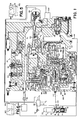
- a conventional gas turbine engine 10 shown in Figure 1 has an air inlet 12, an air compressor 14, a plurality of combustion chambers 16, 16"', a gas turbine 18 connected via a shaft 20 to the compressor 14 to drive the same, and an exhaust nozzle 22 from which the products of combustion are expelled to the atmosphere.
- a plurality of fuel injection nozzle 24 connected to a fuel manifold 26 are adapted to inject metered pressurized fuel into the combustion chambers 16, 16N where the resulting air fuel mixture is burned to generate hot motive gas that passes through turbine 18 to drive compressor 14 and thereafter exhausted though nozzle 22 into the atmosphere to generate a propelling thrust.
- a metered flow of fuel is supplied to fuel manifold 26 from fuel tank 28 by an engine driven fuel pump 30 of the positive displacement type.
- a fuel management system 32 including a hydromechanical governor control section 34 and an electronic sensing and signal computer 36 which controls the flow of fuel to the fuel manifold 26.
- the electronic sensing and signal computing section 36 is structurally and operationally conventional in that it receives electrical input signals representing selected variable conditions of engine operation as, for example, engine speed N, compressor discharge air pressure P c , power lever 35 position PLA and compressor inlet air temperature T ; or other engine temperatures.
- the electrical input signals are sensed and compared electronically in a conventional manner resulting in a computed electrical signal which may be suitably amplified and discharged as an electrical output signal to operate the electrohydraulic servovalve 500 and the resolver 48 which position a metering valve 50 to control the flow of fuel to the fuel manifold 26 by way of conduit 46.
- the metering valve 50 has a flat plate 52 that controls the flow of fuel through a triangular shaped port 54 to conduit 46 in response to movement of stem 56 by the operation of the electronic computer 36 input to resolver 48.
- a portion of the fuel flowing from pump 30 is diverted through conduit 61 to servo regulator valves 60 and 62 to provide an operational fluid having a substantially constant pressure P c .
- P 1 When the supply fuel reaches the metering valve 50 through conduit 58 it has a fluid pressure P 1 .
- the restricted flow of the fuel through port 54 produces a pressure drop such that the fuel supplied to the fuel manifold now has a fluid pressure P 2 .
- the rotation of shaft 20 in turbine 10 is a direct function of the position of metering valve plate 52 and the pressure differential (P 1 -P 2 ) established across metering valve plate 52.
- a head sensor 64 has a bellows 66 which receives the fluid pressure P 1 from the metering valve 50 and acts on a movable member 68.
- Moveable member 68 has a face 70 which is urged toward seat 72 by an adjustable spring 74 and the fluid pressure P 2 which is communicated from conduit 46 by way of conduit 47 connected to shut off shuttle valve 76.
- a series of bi-metal disc 78 concentrically positioned inside spring 74 provides for changes in temperature that could affect the specific gravity of the fuel supplied to fuel manifold 26.
- a bypass valve 80 of the type disclosed in United States patent 3,106,934 is connected to the head sensor 64 has a sleeve 82 located in a bore 84.
- Sleeve 82 is of the integrating and proportional flow type disclosed in United States Patent 3,106,934 which is attached to an integrator piston 86 which separates P 2 P chamber 94 from a reference or P x chamber 96.
- Sleeve 82 has a series of openings 88, 88'...88 located adjacent to the end thereof to control communication from bore 84 to port 92 in return conduit 95 connected to reservoir 28.
- a spring 98 in P x chamber 96 and the fluid pressure P si act on and urges integrator piston 86 toward chamber 94 in opposition to the fluid pressure P 2 P located in chamber 94.
- a proportional piston 100 located in sleeve 82 has a face 102 on one end and a lip 104 on the other end.
- a spring 106 is located between integrator piston 86 and the proportional piston 100.
- the fluid pressure P 2 P in chamber 94 is communicated to the interior of sleeve 82 by openings 110 and 112.
- the fuel supplied to turbine 10 causes shaft 20 to rotate. This drive rotation is transmitted through flexible conduit 113 to shaft 114 of the mechanical governor system 116.
- the mechanical governor system 116 which includes a flyweight speed mechanism 118, a cam 120, a proportional valve 122, an integrator piston 124 and valve 126 and a flapper valve 128, responds to the rotation of the shaft 20 to prevent an overspeed condition from occurring during operation of the metering valve 50 by the electronic resolver computer 36.
- the flyweight speed mechanism 118 provides the operational speed sense for mechanical governor system 116.
- the shaft 114 rotates as a function of the rotation of shaft 20 in the turbine 10 to move weight 130 and position slide valve 132. Movement of slide valve 132 controls the flow of operational fluid having a fluid pressure P c (fluid from regulator 60) to either conduit 134 or 136 connected to chambers 138 and 140, respectively of cam means 120.
- P c fluid pressure
- Actuator piston 144 which separates chambers 138 from chamber 140 has a rack member 146 which engages piston 148 to rotate shaft 150.
- a cylinder 152 attached to shaft 150 has four contoured surfaces 154, 156, 158 and 160 thereon. Piston 144 moved by the fluid pressure P c of the operational fluid moves rack 146 to rotate shaft 150 and positions the contours 154, 156, 158 and 160 on the cylinder 152 to a location corresponding to the rotation of shaft 20 in the turbine 10.
- Contour 154 has feed back linkage 162 which moves roller 164 which acts on arm 166 to balance the speed force of weights 130 acting on slide valve 132.
- Contour 156 has linkage 168 which is connected to shaft 170 of the proportional valve 122.
- Proportional valve 122 has a land 172 which moves past port 174 to connect chamber 75 in the head sensor 64 with the body of the control 34 through exit port 173.
- port 174 has a rectangular opening 176 and a triangular opening 178.
- Rectangular opening 176 is designed to be opened first and initiate flow from accumulator 180 associated with head sensor 64. If the movement of land 172 by linkage 168 is large, flow occurs through both openings 176 and 178 to provide for an initial pressure drop in the fluid pressure from P 2 to P 2 P.
- Contour 160 has linkage 182 that is connected to both the integrator piston 124 and integrator valve 126.
- the integrator piston 124 separates a first chamber 185 from a second chamber 187.
- Chamber 185 receives operational fluid having a fluid pressure P c while chamber 187 receives fluid from regulator 62 having a fluid pressure P CR which is a substantially constant and regulated fluid pressure.
- Movement of linkage 182 by integrator piston 124 is designed to be at about a 4:1 ratio of the movement of integrator valve 126.
- Valve 126 has a land 184 which moves (see Figure 6) to open port 186 and provides an additional flow path for operational fluid from accumulator 180 to the body 33 through exit port 190 in way of bore 188. With the flow of operational fluid through port 186 to port 190, the fluid pressure drop from P 2 to P 2 P rapidly increases.
- Contour 158 has linkage 192 that is connected to flapper valve 128.
- a spring 194 urges a face 196 against a seat 198 on conduit 200 connected to chamber 185.
- face 196 moves away from seat 198 to lower the fluid pressure in chamber 185 and allow the integrator piston 124 to move toward chamber 185.
- An operator supplies an operational input to power lever 35 to provide the electronic computing section 36 with an input.
- This input along with other operating parameters such as atmospheric air pressure, compressor discharge pressure, engine speed, inlet air temperature, altitude and engine temperature are evaluated in the development of an operational signal that is supplied to electronic computer 36 for moving metering valve 50 to define the opening of port 54 for the flow of fuel into conduit 46 connected to the fuel manifold 26.
- the fuel supplied to fuel manifold 26 is burned in chamber 16 causing an expansion of the gases therein, which on existing nozzle 22 rotates shaft 20.
- the rotation of shaft 20 is directly proportional to the fuel supplied to manifold 26.
- the restriction of the flow of fuel through port 54 causes a pressure drop to occur across the metering valve 50 such that the fuel in conduit 58 has a fluid pressure of P 1 and the fuel in conduit 46 has a fluid pressure of P 2 .
- Fluid pressure P 1 is communicated to the inside of bellows 66, while fluid pressure P 2 P is communicated to bellows 66 by way of shut off valve 76 and conduit 47, to act on the outside of bellows 66 in head sensor 64.
- the pressure differential acting on the moveable member 68 positions face 70 against seat 72 to prevent the communication of operational fluid having a fluid pressure P sf to chamber 75.
- fluid pressure P 2 P is communicated to chamber 94 in the bypass valve 80 to act on both integrator piston 86 and proportional piston 100 to position sleeve 82 and lip 103 with respect to port 92 and set the size of the opening to return conduit 95.
- the integral piston 86 which is controlled by the sensor 64 holds the pressure drop across the bellows 66 constant.
- Rotation of shaft 20 is carried to the governor flyweight speed sensor 118 by flexible shaft 113.
- the weight 130 moves out to pull the spinning slide valve 132 such that land 133 moves past seat 131 to allow fluid having a fluid pressure P c to flow to chamber 138 while at the same time land 135 moves past seat 137 to open chamber 140 to the body pressure P B .
- the pressure differential P c-PB acts on piston 144 to move rack 146 and rotate cam 120 such that the first 154, second 156, third 158 and fourth 160 contours provide an operational input to the flyweight mechanism 118, proportional valve 122, flapper valve 128, and integrator piston checkout feature 124.
- the feedback from the first contour 154 to the flyweight mechanism 118 provides a reaction force which balances the force of the weight 130 on slide valve 132.
- lands 133 and 135 close ports 131 and 137 and interrupt communication of fluid pressure P c to chamber 138.
- contours 156, 158 and 160 are designed to hold the proportional valve 122, integral valve 126 and integral piston 124 and flapper valve 128 in a substantially constant position.
- the mechanical governor 116 As long as the rotation of shaft 20 is below a preset value, the mechanical governor 116 has no effect on the flow of fuel to fuel manifold 26. Should a malfunction occur in the electronic sensing or computing section 36, which directs the electrohydraulic servovalve 500 to move plate 52, such that the fuel supplied to operate the turbine 10 cause the rotational speed to increase above the preset value, the mechanical governor 116 is activated by the rotation of the flyweight 30 acting on the slide valve 132 and movement of the cam means 120.
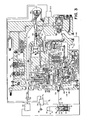
- the overspeed governor system 116 reacts in a manner as shown in figure 2.
- Proportional valve 122 reacts to speed and is brought into operation by the second contour 156.
- Land 172 sequentially moves past openings 176 and 178 (see figure 5) to allow fluid to flow from reservoir 180 to the body 34 through port 173.
- the fluid pressure P 1 acting on face 102 of proportional piston 100 in bypass valve 80 moves piston 100 toward integrator piston 86 to expose more opening 88, 88'...88 and thereby allow a greater percentage of the fuel available in conduit 58 to flow into return conduit 95. This reduction in the volume or pounds of fuel supplied to the turbine 10 should result in a reduction in the shaft 20 rotation.
- the overspeed governor system 118 reacts in a manner as shown in figure 3.
- Proportional valve 122 is fully opened and contour 158 moves flapper valve 128 which moves integral piston 124 to open integral valve 126.
- piston 184 moves past port 186, additional fluid flows from reservoir 180 to further reduce the fluid pressure in chamber 94 to P 2 P. This reduction in fluid pressure allows proportional piston 100 to further open and permit a corresponding increase in the fuel being returned in conduit 95.
- the essence of this invention can be stated as follows: as the delta pressure (P 2 -P 2 P) at the head sensor 64 increases, the delta pressure (P 1 -P 2 ) at the metering valve 50 decreases and as a result the metered fuel flow to the engine 10 results in a reduction in the rotation of the turbine shaft 20 to maintain the rotational speed within a set limit.
Landscapes
- Engineering & Computer Science (AREA)
- Chemical & Material Sciences (AREA)
- Combustion & Propulsion (AREA)
- Mechanical Engineering (AREA)
- General Engineering & Computer Science (AREA)
- Control Of Turbines (AREA)
- Electrical Control Of Air Or Fuel Supplied To Internal-Combustion Engine (AREA)
- High-Pressure Fuel Injection Pump Control (AREA)
Applications Claiming Priority (2)
| Application Number | Priority Date | Filing Date | Title |
|---|---|---|---|
| US07/080,728 US4837697A (en) | 1987-07-31 | 1987-07-31 | Overspeed governor for an electronic controlled fuel system |
| US80728 | 1991-12-13 |
Publications (2)
| Publication Number | Publication Date |
|---|---|
| EP0419453A1 EP0419453A1 (en) | 1991-04-03 |
| EP0419453B1 true EP0419453B1 (en) | 1993-02-03 |
Family
ID=22159236
Family Applications (1)
| Application Number | Title | Priority Date | Filing Date |
|---|---|---|---|
| EP88905039A Expired - Lifetime EP0419453B1 (en) | 1987-07-31 | 1988-02-26 | Overspeed governor for an electronic controlled fuel system |
Country Status (6)
| Country | Link |
|---|---|
| US (1) | US4837697A (enExample) |
| EP (1) | EP0419453B1 (enExample) |
| JP (1) | JPH02501676A (enExample) |
| CA (1) | CA1274698A (enExample) |
| DE (1) | DE3878261T2 (enExample) |
| WO (1) | WO1989001092A1 (enExample) |
Families Citing this family (18)
| Publication number | Priority date | Publication date | Assignee | Title |
|---|---|---|---|---|
| GB8800904D0 (en) * | 1988-01-15 | 1988-02-17 | Rolls Royce Plc | Fuel control system |
| GB8815623D0 (en) * | 1988-06-30 | 1988-08-03 | Rolls Royce Plc | Self-checking speed governor arrangement |
| US5133181A (en) * | 1989-12-28 | 1992-07-28 | Allied-Signal Inc. | Fuel control shut-off system |
| US5207240A (en) * | 1992-09-16 | 1993-05-04 | Allied-Signal Inc. | Self aligning nozzle for a flapper valve |
| US5579632A (en) * | 1995-04-10 | 1996-12-03 | Alliedsignal Inc. | Overspeed governor control system |
| US5789822A (en) * | 1996-08-12 | 1998-08-04 | Revak Turbomachinery Services, Inc. | Speed control system for a prime mover |
| EP1045964B1 (en) | 1998-01-08 | 2012-08-08 | United Technologies Corporation | Bi-level hydraulic pressurizing system |
| US6619027B1 (en) * | 2000-10-13 | 2003-09-16 | General Electric Company | Gas turbine having rotor overspeed and overboost protection |
| US6568166B2 (en) | 2000-12-22 | 2003-05-27 | Pratt & Whitney Canada Corp. | Back-up control apparatus for turbo machine |
| US6655151B2 (en) | 2001-09-07 | 2003-12-02 | Honeywell International, Inc. | Method for controlling fuel flow to a gas turbine engine |
| US8321119B2 (en) * | 2008-07-10 | 2012-11-27 | General Electric Company | Methods and systems to facilitate over-speed protection |
| US20100005657A1 (en) * | 2008-07-10 | 2010-01-14 | Van Vactor David R | Methods and systems to facilitate over-speed protection |
| US8224552B2 (en) * | 2008-07-10 | 2012-07-17 | General Electric Company | Methods and systems to facilitate over-speed protection |
| EP2458181A1 (de) * | 2010-11-30 | 2012-05-30 | Siemens Aktiengesellschaft | Verfahren zum Betreiben einer Gasturbine, Vorrichtung zum Regeln des Betriebs einer Gasturbine und Kraftwerk |
| US10900537B2 (en) | 2012-07-02 | 2021-01-26 | Honeywell International Inc. | Vibration isolator assemblies and methods for the manufacture thereof |
| US9562616B2 (en) * | 2013-01-15 | 2017-02-07 | Honeywell International Inc. | Spring assemblies for use in gas turbine engines and methods for their manufacture |
| US10801361B2 (en) | 2016-09-09 | 2020-10-13 | General Electric Company | System and method for HPT disk over speed prevention |
| CN111102080B (zh) * | 2020-01-19 | 2020-09-29 | 广州珠江天然气发电有限公司 | 一种用于燃气轮机的转速控制装置 |
Family Cites Families (15)
| Publication number | Priority date | Publication date | Assignee | Title |
|---|---|---|---|---|
| GB790007A (en) * | 1954-09-27 | 1958-01-29 | Holley Carburetor Co | Fuel control system for internal combustion engines |
| FR1144275A (fr) * | 1954-12-22 | 1957-10-11 | Bendix Aviat Corp | Régulateur de moteurs |
| US2968345A (en) * | 1956-09-21 | 1961-01-17 | United Aircraft Corp | Speed topping control |
| US3173468A (en) * | 1961-03-30 | 1965-03-16 | Bendix Corp | Fuel control for combustion engines |
| US3374622A (en) * | 1966-06-09 | 1968-03-26 | Lucas Industries Ltd | Fuel systems for gas turbine engines |
| FR2067745A5 (enExample) * | 1969-11-14 | 1971-08-20 | Snecma | |
| US4245462A (en) * | 1978-11-29 | 1981-01-20 | The Bendix Corporation | Starting system for a turbine engine |
| US4344281A (en) * | 1980-04-07 | 1982-08-17 | The Bendix Corporation | Manually operated metering valve for a fuel control |
| US4302931A (en) * | 1980-06-16 | 1981-12-01 | Cnandler Evans Inc. | Fuel flow limiting device for overspeed and overtemperature control |
| US4393651A (en) * | 1980-09-02 | 1983-07-19 | Chandler Evans Inc. | Fuel control method and apparatus |
| US4578945A (en) * | 1983-11-10 | 1986-04-01 | Chandler Evans Inc. | Overspeed limiter for gas turbine fuel control |
| US4602479A (en) * | 1985-06-12 | 1986-07-29 | United Technologies Corporation | Fuel control |
| GB8526726D0 (en) * | 1985-10-30 | 1985-12-04 | Rolls Royce | Failsafe electronic control system |
| FR2594488B1 (fr) * | 1986-02-19 | 1988-05-06 | Snecma | Amelioration aux regulateurs hydromecaniques |
| US4716723A (en) * | 1986-09-05 | 1988-01-05 | Woodward Governor Company | Fuel controls for gas turbine engines |
-
1987
- 1987-07-31 US US07/080,728 patent/US4837697A/en not_active Expired - Lifetime
-
1988
- 1988-02-26 JP JP63504536A patent/JPH02501676A/ja active Granted
- 1988-02-26 WO PCT/US1988/000607 patent/WO1989001092A1/en not_active Ceased
- 1988-02-26 EP EP88905039A patent/EP0419453B1/en not_active Expired - Lifetime
- 1988-02-26 DE DE8888905039T patent/DE3878261T2/de not_active Expired - Fee Related
- 1988-03-24 CA CA000562360A patent/CA1274698A/en not_active Expired
Also Published As
| Publication number | Publication date |
|---|---|
| JPH02501676A (ja) | 1990-06-07 |
| DE3878261T2 (de) | 1993-07-01 |
| EP0419453A1 (en) | 1991-04-03 |
| US4837697A (en) | 1989-06-06 |
| JPH056019B2 (enExample) | 1993-01-25 |
| CA1274698A (en) | 1990-10-02 |
| DE3878261D1 (de) | 1993-03-18 |
| WO1989001092A1 (en) | 1989-02-09 |
Similar Documents
| Publication | Publication Date | Title |
|---|---|---|
| EP0419453B1 (en) | Overspeed governor for an electronic controlled fuel system | |
| US6898939B2 (en) | Methods for rotor overspeed and overboost protection | |
| JPH0580581B2 (enExample) | ||
| EP0037786B1 (en) | Fuel control apparatus | |
| US4245462A (en) | Starting system for a turbine engine | |
| GB1253879A (en) | Fuel metering, speed control, and nozzle positioning control for a gas turbine engine | |
| US2933887A (en) | Compound gas turbine engine with control for low-pressure rotor | |
| US4368618A (en) | Manually operated metering valve for a fuel control | |
| US3487482A (en) | Fuel control | |
| US4835969A (en) | Error detection means for an overspeed governor | |
| US2841957A (en) | Automatic compressor pressure limiter | |
| US3195308A (en) | Fuel control for combustion engine | |
| US3067576A (en) | Co-ordinated main and afterburner fuel controls for a turbojet | |
| US5133181A (en) | Fuel control shut-off system | |
| US5579632A (en) | Overspeed governor control system | |
| US2950857A (en) | Power control system for gas turbine engines | |
| US3257807A (en) | Power plant control system | |
| US3472028A (en) | Aircraft jet engines having afterburners and adjustable jet pipes | |
| US4517796A (en) | Power lever apparatus for a turbine engine | |
| US3062005A (en) | Coordinated variable area nozzle and reheat fuel control for a gas turbine engine | |
| US2958376A (en) | Starting control for internal combustion engines | |
| US3784130A (en) | Fuel systems for aircraft gas turbine engines | |
| US3067580A (en) | Fuel enrichment control for a gas turbine engine | |
| US3348560A (en) | Acceleration force compensator for aircraft prime mover | |
| US2716862A (en) | Fuel regulating valve mechanism |
Legal Events
| Date | Code | Title | Description |
|---|---|---|---|
| PUAI | Public reference made under article 153(3) epc to a published international application that has entered the european phase |
Free format text: ORIGINAL CODE: 0009012 |
|
| 17P | Request for examination filed |
Effective date: 19900129 |
|
| AK | Designated contracting states |
Kind code of ref document: A1 Designated state(s): DE FR GB |
|
| 17Q | First examination report despatched |
Effective date: 19920611 |
|
| GRAA | (expected) grant |
Free format text: ORIGINAL CODE: 0009210 |
|
| AK | Designated contracting states |
Kind code of ref document: B1 Designated state(s): DE FR GB |
|
| REF | Corresponds to: |
Ref document number: 3878261 Country of ref document: DE Date of ref document: 19930318 |
|
| ET | Fr: translation filed | ||
| PLBE | No opposition filed within time limit |
Free format text: ORIGINAL CODE: 0009261 |
|
| STAA | Information on the status of an ep patent application or granted ep patent |
Free format text: STATUS: NO OPPOSITION FILED WITHIN TIME LIMIT |
|
| 26N | No opposition filed | ||
| REG | Reference to a national code |
Ref country code: GB Ref legal event code: IF02 |
|
| PGFP | Annual fee paid to national office [announced via postgrant information from national office to epo] |
Ref country code: DE Payment date: 20040227 Year of fee payment: 17 |
|
| PG25 | Lapsed in a contracting state [announced via postgrant information from national office to epo] |
Ref country code: DE Free format text: LAPSE BECAUSE OF NON-PAYMENT OF DUE FEES Effective date: 20050901 |
|
| PGFP | Annual fee paid to national office [announced via postgrant information from national office to epo] |
Ref country code: GB Payment date: 20070105 Year of fee payment: 20 |
|
| REG | Reference to a national code |
Ref country code: GB Ref legal event code: PE20 |
|
| PGFP | Annual fee paid to national office [announced via postgrant information from national office to epo] |
Ref country code: FR Payment date: 20070201 Year of fee payment: 20 |
|
| PG25 | Lapsed in a contracting state [announced via postgrant information from national office to epo] |
Ref country code: GB Free format text: LAPSE BECAUSE OF EXPIRATION OF PROTECTION Effective date: 20080225 |