EP0419300B1 - Roller with conical shank - Google Patents
Roller with conical shank Download PDFInfo
- Publication number
- EP0419300B1 EP0419300B1 EP90402185A EP90402185A EP0419300B1 EP 0419300 B1 EP0419300 B1 EP 0419300B1 EP 90402185 A EP90402185 A EP 90402185A EP 90402185 A EP90402185 A EP 90402185A EP 0419300 B1 EP0419300 B1 EP 0419300B1
- Authority
- EP
- European Patent Office
- Prior art keywords
- cylinder
- ferrule
- ferrules
- roller
- axle
- Prior art date
- Legal status (The legal status is an assumption and is not a legal conclusion. Google has not performed a legal analysis and makes no representation as to the accuracy of the status listed.)
- Expired - Lifetime
Links
- 239000011819 refractory material Substances 0.000 claims description 4
- 239000002184 metal Substances 0.000 description 6
- 238000004873 anchoring Methods 0.000 description 3
- 239000007787 solid Substances 0.000 description 3
- 229910000831 Steel Inorganic materials 0.000 description 2
- 239000011521 glass Substances 0.000 description 2
- 238000010438 heat treatment Methods 0.000 description 2
- 239000000463 material Substances 0.000 description 2
- 239000010959 steel Substances 0.000 description 2
- 239000000919 ceramic Substances 0.000 description 1
- 230000008602 contraction Effects 0.000 description 1
- 238000006073 displacement reaction Methods 0.000 description 1
Images
Classifications
-
- F—MECHANICAL ENGINEERING; LIGHTING; HEATING; WEAPONS; BLASTING
- F27—FURNACES; KILNS; OVENS; RETORTS
- F27D—DETAILS OR ACCESSORIES OF FURNACES, KILNS, OVENS, OR RETORTS, IN SO FAR AS THEY ARE OF KINDS OCCURRING IN MORE THAN ONE KIND OF FURNACE
- F27D3/00—Charging; Discharging; Manipulation of charge
- F27D3/02—Skids or tracks for heavy objects
- F27D3/026—Skids or tracks for heavy objects transport or conveyor rolls for furnaces; roller rails
-
- B—PERFORMING OPERATIONS; TRANSPORTING
- B29—WORKING OF PLASTICS; WORKING OF SUBSTANCES IN A PLASTIC STATE IN GENERAL
- B29C—SHAPING OR JOINING OF PLASTICS; SHAPING OF MATERIAL IN A PLASTIC STATE, NOT OTHERWISE PROVIDED FOR; AFTER-TREATMENT OF THE SHAPED PRODUCTS, e.g. REPAIRING
- B29C48/00—Extrusion moulding, i.e. expressing the moulding material through a die or nozzle which imparts the desired form; Apparatus therefor
- B29C48/03—Extrusion moulding, i.e. expressing the moulding material through a die or nozzle which imparts the desired form; Apparatus therefor characterised by the shape of the extruded material at extrusion
-
- B—PERFORMING OPERATIONS; TRANSPORTING
- B65—CONVEYING; PACKING; STORING; HANDLING THIN OR FILAMENTARY MATERIAL
- B65G—TRANSPORT OR STORAGE DEVICES, e.g. CONVEYORS FOR LOADING OR TIPPING, SHOP CONVEYOR SYSTEMS OR PNEUMATIC TUBE CONVEYORS
- B65G39/00—Rollers, e.g. drive rollers, or arrangements thereof incorporated in roller-ways or other types of mechanical conveyors
- B65G39/02—Adaptations of individual rollers and supports therefor
- B65G39/07—Other adaptations of sleeves
-
- C—CHEMISTRY; METALLURGY
- C03—GLASS; MINERAL OR SLAG WOOL
- C03B—MANUFACTURE, SHAPING, OR SUPPLEMENTARY PROCESSES
- C03B35/00—Transporting of glass products during their manufacture, e.g. hot glass lenses, prisms
- C03B35/14—Transporting hot glass sheets or ribbons, e.g. by heat-resistant conveyor belts or bands
- C03B35/16—Transporting hot glass sheets or ribbons, e.g. by heat-resistant conveyor belts or bands by roller conveyors
- C03B35/18—Construction of the conveyor rollers ; Materials, coatings or coverings thereof
- C03B35/186—End caps, end fixtures or roller end shape designs
-
- B—PERFORMING OPERATIONS; TRANSPORTING
- B29—WORKING OF PLASTICS; WORKING OF SUBSTANCES IN A PLASTIC STATE IN GENERAL
- B29C—SHAPING OR JOINING OF PLASTICS; SHAPING OF MATERIAL IN A PLASTIC STATE, NOT OTHERWISE PROVIDED FOR; AFTER-TREATMENT OF THE SHAPED PRODUCTS, e.g. REPAIRING
- B29C48/00—Extrusion moulding, i.e. expressing the moulding material through a die or nozzle which imparts the desired form; Apparatus therefor
- B29C48/25—Component parts, details or accessories; Auxiliary operations
- B29C48/285—Feeding the extrusion material to the extruder
- B29C48/288—Feeding the extrusion material to the extruder in solid form, e.g. powder or granules
- B29C48/2888—Feeding the extrusion material to the extruder in solid form, e.g. powder or granules in band or in strip form, e.g. rubber strips
Definitions
- This invention relates to rollers mounted rotationally on bearings by means of ferrules, such as rollers designed to support a load that moves on a series of identical rollers mounted side by side.
- This load can include a strip material, such as a sheet of steel or a plate of glass.
- Rollers designed to support a metal strip are known, particularly in a heat treatment furnace in which the strip is annealed at a relatively high temperature.
- Such rollers are typically formed of a cylinder of refractory material and a ferrule rotationally mounted on a bearing is fixed at each end of the cylinder.
- U.S. Patent No. 4,399,598 discloses a ceramic roller for transporting glass sheets in a heat treatment furnace.
- the cylinder is mounted rotationally on bearings by means of ferrules mounted with play at each end of the cylinder.
- One or more split, circumferentially expandable, radially compressible metal rings are located in the space between the outside diameter of the cylinder and the inside diameter of the ferrule where the ferrule overlaps the cylinder.
- EP-A-0 005 012 discloses a roller for use under high or low temperature conditions with a conical configuration of the connection between the cylinder and the ferrules.
- the angle of the cone is such that there is only slidable movement of the frusto-conical surfaces relative to each other.
- Another known roller includes a cylinder of refractory material having metal ferrules affixed at each end. Play is provided between the ferrules and the cylinder and longitudinal metal platelets are embedded in this area of play.
- a roller which includes a cylinder and at least one ferrule mounted at one end of the cylinder.
- the cylinder and the ferrule have a configuration according to claim 1 capable of taking a diametrical play.
- a ferrule is provided at each end of the cylinder and the connection between the cylinder and the ferrules is conical in configuration.
- the roller includes a means for holding the cylinder against the bottom of the conical connection with the ferrules including elastic means.
- a tie rod is anchored at one end of the cylinder and is subject to the force of elastic means at the other end.
- the elastic means can be a helical coil, spring or Belleville type of washers.
- an axle passes axially through the cylinder and the ferrules, with the axle rigidly mounted to a first of the ferrules and with a second of the ferrules subject to the force of elastic means.
- a collar can be rigidly mounted to the axle beyond the second ferrule and include an elastic means extending between the collar and the second ferrule.
- the elastic means is preferably a helical coil spring surrounding the axle.
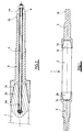
- FIG. 1 The general arrangement of a roller in accordance with the present invention, designated by reference number 1, is shown in FIG. 1.
- This roller includes an elongated cylinder 2 and a ferrule 3 mounted at each end of the cylinder 2.
- the cylinder 2 and each of the two ferrules 3 are shaped so that the joint between the cylinder 2 and each of the ferrules 3 is made without play therebetween.
- this connection is a conical joint.
- the cylinder 2 terminates at each end in a male cone 2a, while each ferrule 3 has at one end thereof a female cone 3a adapted to connect tightly and without play on a male cone 2a of the cylinder 2.
- the ferrules 3 With an increase in the inside diameter of the ferrules 3, e.g., due to thermal expansion, the ferrules 3 will be displaced axially along the cylinder 2 and permit any developing play to be taken up. This maintains a tight connection between the cylinder 2 and the ferrules 3.
- the angle of conicity between the male cone 2a and female cone 3a should be the same and should be greater or equal to the angle of friction between the two materials. If the angle is too large with respect to friction, the joint can be lubricated.
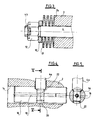
- FIG. 2 shows a particular arrangement that makes it possible to obtain an axial displacement in one direction or the other of a ferrule 3 with respect to an end of the cylinder 2.
- a tie rod 4 passes through the ferrule 3 and is anchored at a first end 4a in the cylinder 2.
- the second end 4b of the tie rod 4 beyond a free end 3b of the ferrule 3 is subjected to the action of an elastic return means 6.
- the first end 4a of the tie rod 4 is anchored in the cylinder 2 by any suitable means and a particular anchoring means is shown in FIG. 4.
- FIG. 3 shows a detailed view of one example of an elastic return means 6 for the tie rod 4 shown in FIG. 2.
- a nut 12 or the like is fixedly attached to the second end 4b of the tie rod 4 and spaced from the free end 3b of the ferrule 3.
- a solid washer 10 is placed around the tie rod 4 adjacent the nut 12 and a series of Belleville washers 8 are positioned around the tie rod 4 between and in contact with the solid washer 10 and the free end 3b of the ferrule 3.
- the Belleville washers 8 exert a force against the free end 3b of the ferrule 3 and keep the female cone 3a of the ferrule 3 in contact with the male cone 2a on the cylinder 2, yet permit relative movement between the ferrule 3 and cylinder 2 due to thermal expansion or contraction.
- FIG. 4 shows a detailed view of an arrangement that permits the anchoring of the free end 4a of the tie rod 4 in the cylinder 2.
- a first cylindrical hole 14 passes diametrically through the cylinder 2.
- a first solid cylindrical pin 16 is inserted through the first hole 14.
- the first pin 16 has a threaded bore 20 therein extending perpendicular to the first hole 14.
- the first end 4a of the tie rod 4 ends in a threaded portion 22 which is screwed into the threaded bore 20.
- the first pin 16 is pierced axially by a second pin 18 which also passes through the threaded portion 22 of the tie rod 4a.
- the second pin 18 is inserted to prevent any accidental unscrewing of the end 4a of the tie rod 4 from the first pin 16. With this assembly, the tie rod 4 is firmly fixed in the cylinder 2 without risk of coming apart.
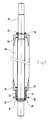
- FIG. 6 A second embodiment of a roller in accordance with the present invention is shown in FIG. 6.
- the roller includes a cylinder 30 and a first ferrule 32 and second ferrule 34 at opposite ends of the cylinder 30 and connected thereto by the same conical arrangement described above in FIGS. 1 and 2.
- the cylinder 30 and ferrules 32, 34 are hollow and include a steel axle 36 passing axially therethrough and beyond the ferrules 32, 34.
- the first ferrule 32 has a sleeve 38 extending outward along the axle 36.
- a pin 40 extends through sleeve 38 and into the axle 36 to mount the first ferrule 32 rigidly thereto.
- the second ferrule 32 also includes a sleeve 42 extending outward along the axle 36.
- a collar 44 including a narrower sleeve 46 and a wider ring 48, is positioned around the axle 36 beyond the second ferrule 34, with the ring 48 facing the second ferrule 34.
- a pin 50 extends through sleeve 46 and into the axle 36 to mount the collar 44 rigidly thereto.
- the second ferrule 34 is free to slide along the axle 36 between the cylinder 30 and the collar 44.
- a helical coil spring 52 surrounds the axle 36 and the sleeve 42 of the second ferrule 34 and extends between and in contact with the ring 48 on the collar 44 and a retaining notch 54 in the second ferrule 34.
- the helical coil spring 52 provides constant force on the second ferrule 34 to maintain the contact between the ferrules 32, 34 and the cylinder 30 when the roller is expanding or contracting due to temperature changes.
Description
- This invention relates to rollers mounted rotationally on bearings by means of ferrules, such as rollers designed to support a load that moves on a series of identical rollers mounted side by side. This load can include a strip material, such as a sheet of steel or a plate of glass.
- Rollers designed to support a metal strip are known, particularly in a heat treatment furnace in which the strip is annealed at a relatively high temperature. Such rollers are typically formed of a cylinder of refractory material and a ferrule rotationally mounted on a bearing is fixed at each end of the cylinder.
- U.S. Patent No. 4,399,598 discloses a ceramic roller for transporting glass sheets in a heat treatment furnace. The cylinder is mounted rotationally on bearings by means of ferrules mounted with play at each end of the cylinder. One or more split, circumferentially expandable, radially compressible metal rings are located in the space between the outside diameter of the cylinder and the inside diameter of the ferrule where the ferrule overlaps the cylinder.
- EP-A-0 005 012 discloses a roller for use under high or low temperature conditions with a conical configuration of the connection between the cylinder and the ferrules. The angle of the cone is such that there is only slidable movement of the frusto-conical surfaces relative to each other.
- Another known roller includes a cylinder of refractory material having metal ferrules affixed at each end. Play is provided between the ferrules and the cylinder and longitudinal metal platelets are embedded in this area of play.
- These known systems of the prior art make it possible for the roller to take up differential dilatation during a temperature change. In effect, the cylinder of refractory material expands very little or not at all, while the metal ferrules expand greatly. As a result, the play between the cylinder and the ferrules varies substantially as a function of the temperature. It becomes necessary to provide elastic devices for taking up the variation in the play between the cylinder and the ferrules.
- Nevertheless, these known arrangements have the disadvantage of not assuring that the ferrule and the cylinder remain coaxial under load. In effect, when the cylinder is supporting a load, the elastic devices, whether the split rings of U.S. Patent No. 4,399,598 or the longitudinal metal platelets, are deformed so that the ferrules are displaced angularly with respect to the axis of the cylinder.
- It is an object of the present invention to provide a roller, including a cylinder and at least one ferrule mounted at the end of the cylinder, which overcomes this disadvantage of the prior art and will take up diametrical play while the cylinder and ferrules remain in coaxial alignment.
- Accordingly, I have developed a roller which includes a cylinder and at least one ferrule mounted at one end of the cylinder. The cylinder and the ferrule have a configuration according to claim 1 capable of taking a diametrical play. According to the invention a ferrule is provided at each end of the cylinder and the connection between the cylinder and the ferrules is conical in configuration. Furthermore the roller includes a means for holding the cylinder against the bottom of the conical connection with the ferrules including elastic means. In a first embodiment, a tie rod is anchored at one end of the cylinder and is subject to the force of elastic means at the other end. The elastic means can be a helical coil, spring or Belleville type of washers. In a second embodiment, an axle passes axially through the cylinder and the ferrules, with the axle rigidly mounted to a first of the ferrules and with a second of the ferrules subject to the force of elastic means. In this second embodiment, a collar can be rigidly mounted to the axle beyond the second ferrule and include an elastic means extending between the collar and the second ferrule. The elastic means is preferably a helical coil spring surrounding the axle.
-
- FIG. 1 is a side view, partially in section, showing the general arrangement of a roller in accordance with the present invention;
- FIG. 2 is a side view, partially in section, of the end of a first embodiment of a roller in accordance with the present invention;
- FIG. 3 is a detailed view, partially in section, showing the end of the ferrule in FIG. 2 and the elastic means of returning the tie rod;
- FIG. 4 is a detailed view showing a preferred means of anchoring the tie rod in the cylinder of FIG. 2;
- FIG. 5 is a section taken along lines V-V in FIG. 4; and
- FIG. 6 is a side view, partially in section, of a second embodiment of a roller in accordance with the present invention.
- The general arrangement of a roller in accordance with the present invention, designated by reference number 1, is shown in FIG. 1. This roller includes an
elongated cylinder 2 and aferrule 3 mounted at each end of thecylinder 2. Thecylinder 2 and each of the twoferrules 3 are shaped so that the joint between thecylinder 2 and each of theferrules 3 is made without play therebetween. In the particular example shown in FIG. 1, this connection is a conical joint. Thecylinder 2 terminates at each end in amale cone 2a, while eachferrule 3 has at one end thereof afemale cone 3a adapted to connect tightly and without play on amale cone 2a of thecylinder 2. With an increase in the inside diameter of theferrules 3, e.g., due to thermal expansion, theferrules 3 will be displaced axially along thecylinder 2 and permit any developing play to be taken up. This maintains a tight connection between thecylinder 2 and theferrules 3. The angle of conicity between themale cone 2a andfemale cone 3a should be the same and should be greater or equal to the angle of friction between the two materials. If the angle is too large with respect to friction, the joint can be lubricated. - FIG. 2 shows a particular arrangement that makes it possible to obtain an axial displacement in one direction or the other of a
ferrule 3 with respect to an end of thecylinder 2. Atie rod 4 passes through theferrule 3 and is anchored at afirst end 4a in thecylinder 2. Thesecond end 4b of thetie rod 4 beyond afree end 3b of theferrule 3 is subjected to the action of an elastic return means 6. Thefirst end 4a of thetie rod 4 is anchored in thecylinder 2 by any suitable means and a particular anchoring means is shown in FIG. 4. - FIG. 3 shows a detailed view of one example of an elastic return means 6 for the
tie rod 4 shown in FIG. 2. Anut 12 or the like is fixedly attached to thesecond end 4b of thetie rod 4 and spaced from thefree end 3b of theferrule 3. Asolid washer 10 is placed around thetie rod 4 adjacent thenut 12 and a series of Belleville washers 8 are positioned around thetie rod 4 between and in contact with thesolid washer 10 and thefree end 3b of theferrule 3. The Belleville washers 8 exert a force against thefree end 3b of theferrule 3 and keep thefemale cone 3a of theferrule 3 in contact with themale cone 2a on thecylinder 2, yet permit relative movement between theferrule 3 andcylinder 2 due to thermal expansion or contraction. - FIG. 4 shows a detailed view of an arrangement that permits the anchoring of the
free end 4a of thetie rod 4 in thecylinder 2. A firstcylindrical hole 14 passes diametrically through thecylinder 2. A first solidcylindrical pin 16 is inserted through thefirst hole 14. Thefirst pin 16 has a threadedbore 20 therein extending perpendicular to thefirst hole 14. Thefirst end 4a of thetie rod 4 ends in a threadedportion 22 which is screwed into the threadedbore 20. Thefirst pin 16 is pierced axially by asecond pin 18 which also passes through the threadedportion 22 of thetie rod 4a. Thesecond pin 18 is inserted to prevent any accidental unscrewing of theend 4a of thetie rod 4 from thefirst pin 16. With this assembly, thetie rod 4 is firmly fixed in thecylinder 2 without risk of coming apart. - A second embodiment of a roller in accordance with the present invention is shown in FIG. 6. The roller includes a
cylinder 30 and afirst ferrule 32 andsecond ferrule 34 at opposite ends of thecylinder 30 and connected thereto by the same conical arrangement described above in FIGS. 1 and 2. Thecylinder 30 andferrules steel axle 36 passing axially therethrough and beyond theferrules first ferrule 32 has asleeve 38 extending outward along theaxle 36. Apin 40 extends throughsleeve 38 and into theaxle 36 to mount thefirst ferrule 32 rigidly thereto. Thesecond ferrule 32 also includes asleeve 42 extending outward along theaxle 36. Acollar 44, including anarrower sleeve 46 and awider ring 48, is positioned around theaxle 36 beyond thesecond ferrule 34, with thering 48 facing thesecond ferrule 34. Apin 50 extends throughsleeve 46 and into theaxle 36 to mount thecollar 44 rigidly thereto. Thesecond ferrule 34 is free to slide along theaxle 36 between thecylinder 30 and thecollar 44. Ahelical coil spring 52 surrounds theaxle 36 and thesleeve 42 of thesecond ferrule 34 and extends between and in contact with thering 48 on thecollar 44 and a retainingnotch 54 in thesecond ferrule 34. Thehelical coil spring 52 provides constant force on thesecond ferrule 34 to maintain the contact between theferrules cylinder 30 when the roller is expanding or contracting due to temperature changes. - Having described above the presently preferred embodiments of the present invention, it is to be understood that it may be otherwise embodied within the scope of the appended claims.
Claims (5)
- A roller for carrying a load under varying temperature conditions, said roller being comprising of a cylinder (2, 30) made of a refractory material ending in at least a frustro-conical end (2a) and at least one ferrule (3, 32, 34) having a frusto-conical bore (3a) matching with the frusto-conical end (2a) of the cylinder ; and means for holding the frustro-conical end of the cylinder against the frustro-conical bore of the ferrule,; and the means for holding the frustro-conical end of the cylinder against the frustro-conical bore of the ferrule include elastic means (8, 42) so as to take up a differential dilatation between the cylinder and the ferrule.
- The roller according to claim 1 wherein the means for holding the cylinder against the ferrule include a tie rod (4) anchored at one end in the cylinder (2) and subject to the force of elastic means (8) at the other end.
- The roller according to claim 1 further including a ferrule (32, 34) at each end of the cylinder, wherein the means for holding the cylinder (30) against frustro-conical bore include an axle (36) passing axially through the cylinder (30) and the ferrules (32, 34), with the axle rigidly mounted to a first (32) of said ferrules and with a second (34) of said ferrules subject to the force of elastic means (42).
- The roller according to claim 3 further including a collar (48) rigidly mounted to said axle (36) beyond said second ferrule (34) and with an elastic means (42) extending between said collar and said second ferrule.
- The roller according to claim 4 wherein said elastic means is a helical coil spring (42) surrounding said axle.
Applications Claiming Priority (2)
| Application Number | Priority Date | Filing Date | Title |
|---|---|---|---|
| FR8910587 | 1989-08-03 | ||
| FR8910587A FR2650576A1 (en) | 1989-08-03 | 1989-08-03 | MOUNTING WITHOUT A GAME ON A TIP OF A ROLLER SUCH AS A HANDLING ROLLER SUBJECT TO HIGH TEMPERATURES |
Publications (3)
| Publication Number | Publication Date |
|---|---|
| EP0419300A2 EP0419300A2 (en) | 1991-03-27 |
| EP0419300A3 EP0419300A3 (en) | 1991-12-18 |
| EP0419300B1 true EP0419300B1 (en) | 1994-04-13 |
Family
ID=9384519
Family Applications (1)
| Application Number | Title | Priority Date | Filing Date |
|---|---|---|---|
| EP90402185A Expired - Lifetime EP0419300B1 (en) | 1989-08-03 | 1990-07-30 | Roller with conical shank |
Country Status (6)
| Country | Link |
|---|---|
| US (1) | US5096051A (en) |
| EP (1) | EP0419300B1 (en) |
| JP (1) | JPH0395011A (en) |
| DE (1) | DE69008091T2 (en) |
| ES (1) | ES2055367T3 (en) |
| FR (1) | FR2650576A1 (en) |
Families Citing this family (12)
| Publication number | Priority date | Publication date | Assignee | Title |
|---|---|---|---|---|
| FR2702202B1 (en) * | 1993-03-05 | 1995-04-14 | Vesuvius France Sa | Roller mounted rotating on bearings by a ball joint. |
| DE4430335A1 (en) * | 1994-08-26 | 1996-02-29 | Lwk Plasmaceramic Internationa | Hollow ceramic conveyor roller, esp. for continuous=flow furnace |
| US5971137A (en) * | 1998-03-25 | 1999-10-26 | Comau North America, Inc. | Power roller conveyor |
| CN101263234B (en) * | 2005-09-13 | 2010-10-13 | Posco公司 | Hearth roll apparatus for annealing furnace |
| CN101984089A (en) * | 2010-11-29 | 2011-03-09 | 维苏威赛璐珂陶瓷(苏州)有限公司 | Novel annealing roller |
| US20120241279A1 (en) * | 2011-03-21 | 2012-09-27 | General Electric Company | Load coupling for power generation systems |
| JP6111926B2 (en) * | 2013-07-29 | 2017-04-12 | 日本電気硝子株式会社 | Glass manufacturing equipment |
| US9676651B2 (en) * | 2014-08-07 | 2017-06-13 | Corning Incorporated | Pull-roll cartridges for use in glass manufacturing processes and methods for making and using the same |
| CN105003527B (en) * | 2015-07-07 | 2017-10-20 | 烟台开发区蓝鲸金属修复有限公司 | A kind of manufacture method of steel ceramic combination roller |
| JP2017043788A (en) * | 2015-08-24 | 2017-03-02 | 三建産業株式会社 | Roller mechanism for heating furnace |
| TWI725989B (en) * | 2015-09-18 | 2021-05-01 | 法商維蘇威法國公司 | Conveyor roll assembly for use at high temperature and process for making the same |
| DE102020107036A1 (en) * | 2020-03-13 | 2021-09-16 | Schwartz Gmbh | Storage of a ceramic roll in a roller hearth furnace |
Family Cites Families (12)
| Publication number | Priority date | Publication date | Assignee | Title |
|---|---|---|---|---|
| US2788957A (en) * | 1953-03-30 | 1957-04-16 | Drever Co | Refractory roller furnace conveyor system |
| US2949852A (en) * | 1959-05-01 | 1960-08-23 | Reynolds Metals Co | Printing roll |
| DE1508543A1 (en) * | 1966-07-06 | 1969-10-30 | Siemens Gmbh | Conveyor roll for roll stoves |
| US3867748A (en) * | 1974-03-07 | 1975-02-25 | Libbey Owens Ford Co | Supporting and driving frangible rollers |
| US3994380A (en) * | 1976-01-05 | 1976-11-30 | Hope Henry F | Transport roller |
| DE2717055A1 (en) * | 1977-04-18 | 1978-10-19 | Siemens Ag | DEVICE FOR STORING A DRUM USED AS AN INTERMEDIATE CARRIER IN AN ELECTROSTATIC PRINCIPLE PRINTER OR COPY DEVICE |
| FR2409472A1 (en) * | 1977-11-19 | 1979-06-15 | Lingl Anlagenbau | METHOD AND DEVICE FOR MOUNTING THE DRIVE ROLLERS IN A TUNNEL OVEN |
| EP0005012B1 (en) * | 1978-04-14 | 1983-01-26 | Pilkington Brothers P.L.C. | A roll for use under high or low temperature conditions |
| US4352230A (en) * | 1980-01-11 | 1982-10-05 | New Hudson Corporation | Fiber covered roller for high temperature applications |
| US4399598A (en) * | 1981-03-06 | 1983-08-23 | Ppg Industries, Inc. | Ceramic rolls with metal end caps |
| US4448302A (en) * | 1981-11-23 | 1984-05-15 | Prime & Weaver Investment Company | Roller conveyor construction |
| GB2201750B (en) * | 1987-03-06 | 1990-05-30 | Dyson Refractories | Rollers with end caps |
-
1989
- 1989-08-03 FR FR8910587A patent/FR2650576A1/en active Granted
-
1990
- 1990-07-19 US US07/555,237 patent/US5096051A/en not_active Expired - Fee Related
- 1990-07-30 DE DE69008091T patent/DE69008091T2/en not_active Expired - Fee Related
- 1990-07-30 EP EP90402185A patent/EP0419300B1/en not_active Expired - Lifetime
- 1990-07-30 ES ES90402185T patent/ES2055367T3/en not_active Expired - Lifetime
- 1990-08-02 JP JP2205906A patent/JPH0395011A/en active Pending
Also Published As
| Publication number | Publication date |
|---|---|
| DE69008091T2 (en) | 1994-10-06 |
| ES2055367T3 (en) | 1994-08-16 |
| FR2650576A1 (en) | 1991-02-08 |
| EP0419300A2 (en) | 1991-03-27 |
| DE69008091D1 (en) | 1994-05-19 |
| FR2650576B1 (en) | 1994-12-30 |
| US5096051A (en) | 1992-03-17 |
| EP0419300A3 (en) | 1991-12-18 |
| JPH0395011A (en) | 1991-04-19 |
Similar Documents
| Publication | Publication Date | Title |
|---|---|---|
| EP0419300B1 (en) | Roller with conical shank | |
| EP0005012B1 (en) | A roll for use under high or low temperature conditions | |
| US4834569A (en) | Thermal expansion compensating joint assembly | |
| US4968200A (en) | Expansion anchor assembly | |
| JPH0250324B2 (en) | ||
| KR100308410B1 (en) | Ball socket joints for connecting ceramic rollers to bearings | |
| US5316129A (en) | Ceramic conveyor roll having flat-sided spring retainer for non-rotatably mounting end caps to roller | |
| US4531855A (en) | Adjustable arm | |
| TWI801368B (en) | Kit of parts for mechanically coupling a ceramic element to a rod and conveyor roller assembly for a conveyor system | |
| PL309145A1 (en) | Anchor bolt tension monitoring element | |
| US5267798A (en) | Bearing assembly | |
| JPS5839248B2 (en) | Synthetic roll with roll ring made of tensile strength sensitive material | |
| US4934979A (en) | Bearing assembly for hookes universal joint | |
| KR102614984B1 (en) | Conveyor roll assemblies, torque transmission and support means, and methods for manufacturing conveyor roll assemblies used in high temperature environments | |
| US3602010A (en) | Shaft coupling means for high temperature rolls and the like | |
| JPS586807Y2 (en) | Roll thermal expansion absorption mechanism | |
| GB2058266A (en) | Fitting for attachment to perforated members | |
| WO2020061260A1 (en) | Conveyor roll end cap assembly | |
| US6623225B1 (en) | Expandable bolt and use for fragile parts | |
| GB2121139A (en) | A device for releasably connecting two shafts together | |
| DE2905614C2 (en) | ||
| GB2190980A (en) | Hookes universal joint having angle limiting means | |
| EP0561377A2 (en) | A rolling element bearing, particularly for a wheel assembly of a vehicle | |
| SU703686A1 (en) | Apparatus for axial retaining of hub on a shaft | |
| RU2134182C1 (en) | Mandrel for centering and attachment of thin-walled part |
Legal Events
| Date | Code | Title | Description |
|---|---|---|---|
| PUAI | Public reference made under article 153(3) epc to a published international application that has entered the european phase |
Free format text: ORIGINAL CODE: 0009012 |
|
| AK | Designated contracting states |
Kind code of ref document: A2 Designated state(s): BE DE ES FR GB IT |
|
| PUAL | Search report despatched |
Free format text: ORIGINAL CODE: 0009013 |
|
| 17P | Request for examination filed |
Effective date: 19910912 |
|
| AK | Designated contracting states |
Kind code of ref document: A3 Designated state(s): BE DE ES FR GB IT |
|
| 17Q | First examination report despatched |
Effective date: 19930429 |
|
| GRAA | (expected) grant |
Free format text: ORIGINAL CODE: 0009210 |
|
| AK | Designated contracting states |
Kind code of ref document: B1 Designated state(s): BE DE ES FR GB IT |
|
| REF | Corresponds to: |
Ref document number: 69008091 Country of ref document: DE Date of ref document: 19940519 |
|
| ITF | It: translation for a ep patent filed |
Owner name: JACOBACCI CASETTA & PERANI S.P.A. |
|
| ET | Fr: translation filed | ||
| REG | Reference to a national code |
Ref country code: ES Ref legal event code: FG2A Ref document number: 2055367 Country of ref document: ES Kind code of ref document: T3 |
|
| PLBE | No opposition filed within time limit |
Free format text: ORIGINAL CODE: 0009261 |
|
| STAA | Information on the status of an ep patent application or granted ep patent |
Free format text: STATUS: NO OPPOSITION FILED WITHIN TIME LIMIT |
|
| 26N | No opposition filed | ||
| PGFP | Annual fee paid to national office [announced via postgrant information from national office to epo] |
Ref country code: FR Payment date: 19980618 Year of fee payment: 9 |
|
| PGFP | Annual fee paid to national office [announced via postgrant information from national office to epo] |
Ref country code: DE Payment date: 19980625 Year of fee payment: 9 |
|
| PGFP | Annual fee paid to national office [announced via postgrant information from national office to epo] |
Ref country code: GB Payment date: 19980626 Year of fee payment: 9 |
|
| PGFP | Annual fee paid to national office [announced via postgrant information from national office to epo] |
Ref country code: BE Payment date: 19980714 Year of fee payment: 9 |
|
| PGFP | Annual fee paid to national office [announced via postgrant information from national office to epo] |
Ref country code: ES Payment date: 19980715 Year of fee payment: 9 |
|
| PG25 | Lapsed in a contracting state [announced via postgrant information from national office to epo] |
Ref country code: GB Free format text: LAPSE BECAUSE OF NON-PAYMENT OF DUE FEES Effective date: 19990730 |
|
| PG25 | Lapsed in a contracting state [announced via postgrant information from national office to epo] |
Ref country code: FR Free format text: THE PATENT HAS BEEN ANNULLED BY A DECISION OF A NATIONAL AUTHORITY Effective date: 19990731 Ref country code: ES Free format text: LAPSE BECAUSE OF NON-PAYMENT OF DUE FEES Effective date: 19990731 Ref country code: BE Free format text: LAPSE BECAUSE OF NON-PAYMENT OF DUE FEES Effective date: 19990731 |
|
| BERE | Be: lapsed |
Owner name: S.A. VESUVIUS FRANCE Effective date: 19990731 |
|
| GBPC | Gb: european patent ceased through non-payment of renewal fee |
Effective date: 19990730 |
|
| PG25 | Lapsed in a contracting state [announced via postgrant information from national office to epo] |
Ref country code: DE Free format text: LAPSE BECAUSE OF NON-PAYMENT OF DUE FEES Effective date: 20000503 |
|
| REG | Reference to a national code |
Ref country code: FR Ref legal event code: ST |
|
| REG | Reference to a national code |
Ref country code: ES Ref legal event code: FD2A Effective date: 20000810 |
|
| PG25 | Lapsed in a contracting state [announced via postgrant information from national office to epo] |
Ref country code: IT Free format text: LAPSE BECAUSE OF NON-PAYMENT OF DUE FEES;WARNING: LAPSES OF ITALIAN PATENTS WITH EFFECTIVE DATE BEFORE 2007 MAY HAVE OCCURRED AT ANY TIME BEFORE 2007. THE CORRECT EFFECTIVE DATE MAY BE DIFFERENT FROM THE ONE RECORDED. Effective date: 20050730 |