EP0419014A1 - Kraftstoffeinspritzsystem - Google Patents
Kraftstoffeinspritzsystem Download PDFInfo
- Publication number
- EP0419014A1 EP0419014A1 EP90308315A EP90308315A EP0419014A1 EP 0419014 A1 EP0419014 A1 EP 0419014A1 EP 90308315 A EP90308315 A EP 90308315A EP 90308315 A EP90308315 A EP 90308315A EP 0419014 A1 EP0419014 A1 EP 0419014A1
- Authority
- EP
- European Patent Office
- Prior art keywords
- fuel
- valve
- pump
- spill valve
- engine
- Prior art date
- Legal status (The legal status is an assumption and is not a legal conclusion. Google has not performed a legal analysis and makes no representation as to the accuracy of the status listed.)
- Withdrawn
Links
Images

Classifications
-
- F—MECHANICAL ENGINEERING; LIGHTING; HEATING; WEAPONS; BLASTING
- F02—COMBUSTION ENGINES; HOT-GAS OR COMBUSTION-PRODUCT ENGINE PLANTS
- F02M—SUPPLYING COMBUSTION ENGINES IN GENERAL WITH COMBUSTIBLE MIXTURES OR CONSTITUENTS THEREOF
- F02M59/00—Pumps specially adapted for fuel-injection and not provided for in groups F02M39/00 -F02M57/00, e.g. rotary cylinder-block type of pumps
- F02M59/20—Varying fuel delivery in quantity or timing
- F02M59/36—Varying fuel delivery in quantity or timing by variably-timed valves controlling fuel passages to pumping elements or overflow passages
- F02M59/366—Valves being actuated electrically
Definitions
- This invention relates to a fuel injection system for supplying fuel to an internal combustion engine and of the kind comprising a high pressure fuel pump including a cam actuated pumping plunger, the cam being driven in use by the associated engine, a fuel injection nozzle positioned to direct fuel into a combustion chamber of the engine and mounted remote from the pump and connected thereto by a high pressure pipe line, and a spill valve operable to spill fuel delivered by the pump during a working stroke of the plunger thereby to terminate delivery of fuel through the injection nozzle to the engine.
- the object of the present invention is to provide a system of the kind specified in a simple and convenient form.
- the spill valve is positioned adjacent the fuel injection nozzle.
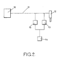
- the fuel injection system comprises a high pressure fuel pump 10 having an outlet which is connected through a delivery valve 6, by a high pressure pipe line 11 to the inlet of a fuel injection nozzle 12.
- the pump includes a pumping plunger 9 which is movable inwardly in a bore 8 by means of a cam 7.
- the cam is a rotary cam but it can be a fixed cam such as is found in a distributor type of pump.
- Fuel is supplied to the bore 8 when a filling port 5 connected to a source 4 of fuel under pressure is covered by the plunger during the initial portion of its inward movement.
- the nozzle in use is positioned to direct fuel into a combustion space of an associated engine and the pump 10 is mounted on the engine at a position remote from the nozzle.
- the injection nozzle 12 is also of conventional form having a fuel pressure actuated valve member which is moved by the fuel pressure to move the valve member against the action of a spring 16 to allow fuel flow through an outlet.
- a spill valve 13 the operation of which is controlled by an electro-magnetic actuator 17.
- the flow of current to the actuator 17 is determined by an electronic control system (not shown).
- the spill valve 13 is mounted in the same body to which the nozzle is attached. However, the spill valve can form a separate component which would be located in close proximity to the nozzle.
- the spill valve includes a valve member 18 slidable in a bore in a valve body 19, the valve member defining a head 20 engageable with a seating defined by the body. Beneath the head the valve member and the body define a chamber 21 which is connected to the inlet of the nozzle.
- the valve member is biased by a spring to the open position in which fuel can flow from the chamber 21 into a further chamber 22 from which extends an outlet 23.
- the valve member 18 is coupled to the armature 24 of the actuator, the armature being of stepped form and the actuator also includes a stator 25 defining ribs presented to the steps defined by the armature.
- the stator also carries a plurality of windings and when the latter are supplied with electric current, the armature assumes the position shown in the drawing and the head 20 of the valve member is held in engagement with the seating to prevent flow of fuel between the inlet of the nozzle and the outlet 23.
- the flow of fuel from the outlet 23 of the spill valve 13 is conveniently controlled by a back pressure control 14 which is shown as a simple restrictor.
- the control may be pressure relief valve or a spring controlled piston which can absorb the spilled fuel and also regulate the residual pressure in the pipe line.
- the actuator 17 associated with the spill valve is energised in order to close the valve head 20 onto the seating and at the commencement of the working stroke of the plunger the fuel in the pipe line 11 will be pressurised and the valve member in the nozzle opened against the action of its spring to permit fuel flow to the engine.
- the actuator is de-energised and the valve head of the spill valve is moved to the open position.
- the pressure in the pipe line 11 adjacent the injection nozzle falls quickly thereby allowing the valve member in the nozzle to move quickly to the closed position.
- the pressure in the pipe line is controlled by the back pressure control 14 which will restrict the rate at which the pressure can collapse and as stated, the control may be such that a residual pressure is maintained in the pipe line.
- the quantity of fuel which is supplied to the associated engine may be varied by opening the spill valve at an appropriate instant in time following the commencement of delivery of fuel by the pump.
- the spill valve may be opened at a pre-determined position of the plunger of the pump in its bore in which case the quantity of fuel is controlled by varying the length of the working stroke of the plunger using for example a helical groove on the plunger which controls the start of fuel delivery by the pump.
- valve 15 there is an additional valve 15 and this valve is also actuated by an electro-magnetic actuator under the control of the electronic control system and in this case the valve 15 is closed by energising the associated actuator, to initiate the delivery of fuel through the injection nozzle. It is convenient for the closing movement of valve 15 to be assisted by the developing fuel pressure in the pipe line and for the opening movement of the valve 13 to be assisted by the fuel pressure in the pipeline. In this case therefore the valve 13 would be closed before the valve 15 in order to minimise the size of the actuator required.
- the valves can be provided with balanced valve members.
- the quantity of fuel delivered to the associated engine is determined by the displacement of fuel which takes place when both valves are closed. If it is required to vary the timing of fuel delivery for a given quantity of fuel the time at which the actuators of the valves are de-energised must be altered by the same amount assuming of course that the cam which actuates the pump plunger has a constant rate. If the cam does not have a constant rate the shape of the cam must be taken into account by the associated control system and this can be achieved by the use of suitable maps. The resilience of the fuel column must also be taken into account it being understood that when fuel delivery takes place soon after the start of inward movement of the plunger there will be a greater volume of fuel in the system than when delivery takes place later in the inward stroke of the pump plunger.
Applications Claiming Priority (2)
| Application Number | Priority Date | Filing Date | Title |
|---|---|---|---|
| GB898918432A GB8918432D0 (en) | 1989-08-12 | 1989-08-12 | Fuel injection system |
| GB8918432 | 1989-08-12 |
Publications (1)
| Publication Number | Publication Date |
|---|---|
| EP0419014A1 true EP0419014A1 (de) | 1991-03-27 |
Family
ID=10661540
Family Applications (1)
| Application Number | Title | Priority Date | Filing Date |
|---|---|---|---|
| EP90308315A Withdrawn EP0419014A1 (de) | 1989-08-12 | 1990-07-30 | Kraftstoffeinspritzsystem |
Country Status (3)
| Country | Link |
|---|---|
| EP (1) | EP0419014A1 (de) |
| JP (1) | JPH0385367A (de) |
| GB (1) | GB8918432D0 (de) |
Cited By (2)
| Publication number | Priority date | Publication date | Assignee | Title |
|---|---|---|---|---|
| US5619483A (en) * | 1993-01-06 | 1997-04-08 | Sony Corporation | Method of recording on a recording medium employing an automatic termination of recording by monitoring the signal being recorded |
| DE19701558A1 (de) * | 1997-01-17 | 1998-05-20 | Daimler Benz Ag | Steuerung der Kraftstoffeinspritzung für eine Brennkraftmaschine |
Citations (4)
| Publication number | Priority date | Publication date | Assignee | Title |
|---|---|---|---|---|
| FR2095695A5 (de) * | 1967-05-03 | 1972-02-11 | Kloeckner Humboldt Deutz Ag | |
| GB2125116A (en) * | 1982-08-03 | 1984-02-29 | Lucas Ind Plc | Reciprocable plunger fuel injection pump |
| US4586656A (en) * | 1984-08-14 | 1986-05-06 | United Technologies Diesel Systems, Inc. | Solenoid valve, particularly as bypass valve with fuel injector |
| EP0178427B1 (de) * | 1984-09-14 | 1990-12-27 | Robert Bosch Gmbh | Elektrisch gesteuerte Kraftstoffeinspritzpumpe für Brennkraftmaschinen |
-
1989
- 1989-08-12 GB GB898918432A patent/GB8918432D0/en active Pending
-
1990
- 1990-07-30 EP EP90308315A patent/EP0419014A1/de not_active Withdrawn
- 1990-08-10 JP JP21057290A patent/JPH0385367A/ja active Pending
Patent Citations (4)
| Publication number | Priority date | Publication date | Assignee | Title |
|---|---|---|---|---|
| FR2095695A5 (de) * | 1967-05-03 | 1972-02-11 | Kloeckner Humboldt Deutz Ag | |
| GB2125116A (en) * | 1982-08-03 | 1984-02-29 | Lucas Ind Plc | Reciprocable plunger fuel injection pump |
| US4586656A (en) * | 1984-08-14 | 1986-05-06 | United Technologies Diesel Systems, Inc. | Solenoid valve, particularly as bypass valve with fuel injector |
| EP0178427B1 (de) * | 1984-09-14 | 1990-12-27 | Robert Bosch Gmbh | Elektrisch gesteuerte Kraftstoffeinspritzpumpe für Brennkraftmaschinen |
Non-Patent Citations (1)
| Title |
|---|
| SHIPBUILDING & MARINE ENGINEERING INT., vol. 104, no. 1253, November 1981, pages 473-476, London, GB; L. BRYCE: "Electronically-controlled fuel injection for medium-speed engines" * |
Cited By (3)
| Publication number | Priority date | Publication date | Assignee | Title |
|---|---|---|---|---|
| US5619483A (en) * | 1993-01-06 | 1997-04-08 | Sony Corporation | Method of recording on a recording medium employing an automatic termination of recording by monitoring the signal being recorded |
| DE19701558A1 (de) * | 1997-01-17 | 1998-05-20 | Daimler Benz Ag | Steuerung der Kraftstoffeinspritzung für eine Brennkraftmaschine |
| FR2758593A1 (fr) * | 1997-01-17 | 1998-07-24 | Daimler Benz Ag | Commande de l'injection de carburant pour un moteur a combustion interne |
Also Published As
| Publication number | Publication date |
|---|---|
| JPH0385367A (ja) | 1991-04-10 |
| GB8918432D0 (en) | 1989-09-20 |
Similar Documents
| Publication | Publication Date | Title |
|---|---|---|
| US3587547A (en) | Fuel injection system and apparatus for use therein | |
| US4811715A (en) | Electronic unit injector | |
| EP0823550A1 (de) | Einspritzventil | |
| EP0889230B1 (de) | Kraftstoffeinspritzventil | |
| JPH06323220A (ja) | 内燃機関の燃料噴射装置 | |
| CA1189400A (en) | Electrically controlled unit injector | |
| US4474158A (en) | Liquid fuel pumping apparatus | |
| US5762033A (en) | Injection device for combined injection of fuel and supplementary fluid or liquid | |
| US4385610A (en) | Fuel injection pump for combustion engines | |
| US5025768A (en) | Fuel injection system for internal combustion engines | |
| US5458103A (en) | Fuel injection arrangement for internal combustion engines | |
| EP0603221B1 (de) | Kraftstoffeinspritzpumpe | |
| EP0419014A1 (de) | Kraftstoffeinspritzsystem | |
| EP0736686B1 (de) | Kraftstoffeinspritzpumpensteuerung | |
| US5333588A (en) | Pump/injector | |
| US4699112A (en) | Fuel injection pump for diesel engines | |
| US4993926A (en) | Fuel pumping apparatus | |
| US4793315A (en) | Fuel pumping apparatus | |
| GB2109058A (en) | Liquid fuel pumping apparatus | |
| CA1170903A (en) | Single solenoid floating piston distributor pump | |
| EP0992675A2 (de) | Brennstoffsystem | |
| EP1065368A2 (de) | Kraftstoffeinspritzventil | |
| EP0821154B1 (de) | Kraftstoffpumpenvorrichtung | |
| EP0413454A1 (de) | Pumpedüse | |
| EP0051530A1 (de) | Regeleinrichtung zum Steuern der Kraftstoffzufuhr von Verbrennungsmotoren |
Legal Events
| Date | Code | Title | Description |
|---|---|---|---|
| PUAI | Public reference made under article 153(3) epc to a published international application that has entered the european phase |
Free format text: ORIGINAL CODE: 0009012 |
|
| AK | Designated contracting states |
Kind code of ref document: A1 Designated state(s): DE ES FR GB IT |
|
| STAA | Information on the status of an ep patent application or granted ep patent |
Free format text: STATUS: THE APPLICATION IS DEEMED TO BE WITHDRAWN |
|
| 18D | Application deemed to be withdrawn |
Effective date: 19910930 |