EP0418637B1 - Switch for a switch clock module - Google Patents
Switch for a switch clock module Download PDFInfo
- Publication number
- EP0418637B1 EP0418637B1 EP90116939A EP90116939A EP0418637B1 EP 0418637 B1 EP0418637 B1 EP 0418637B1 EP 90116939 A EP90116939 A EP 90116939A EP 90116939 A EP90116939 A EP 90116939A EP 0418637 B1 EP0418637 B1 EP 0418637B1
- Authority
- EP
- European Patent Office
- Prior art keywords
- switch
- switching
- ring
- cup
- switching ring
- Prior art date
- Legal status (The legal status is an assumption and is not a legal conclusion. Google has not performed a legal analysis and makes no representation as to the accuracy of the status listed.)
- Expired - Lifetime
Links
Images

Classifications
-
- H—ELECTRICITY
- H01—ELECTRIC ELEMENTS
- H01H—ELECTRIC SWITCHES; RELAYS; SELECTORS; EMERGENCY PROTECTIVE DEVICES
- H01H43/00—Time or time-programme switches providing a choice of time-intervals for executing one or more switching actions and automatically terminating their operations after the programme is completed
- H01H43/02—Details
- H01H43/028—Means for manually actuating the contacts or interfering with the cooperation between timer mechanism and contacts
-
- H—ELECTRICITY
- H01—ELECTRIC ELEMENTS
- H01H—ELECTRIC SWITCHES; RELAYS; SELECTORS; EMERGENCY PROTECTIVE DEVICES
- H01H43/00—Time or time-programme switches providing a choice of time-intervals for executing one or more switching actions and automatically terminating their operations after the programme is completed
- H01H43/02—Details
- H01H43/04—Means for time setting
- H01H43/06—Means for time setting comprising separately adjustable parts for each programme step, e.g. with tappets
Definitions
- the innovation relates to a switch for a time switch module with a switching disk that carries switching riders arranged on the circumference and with a switching lever for scanning the switching riders from the inside of the switching disk, the switch consisting of a fastening piece and one on it in several switching positions transverse to the deflection direction of the shift lever movable slide switch is attached to the frame of the timer module and interacts with the shift lever.
- the innovation is based on a switch of the aforementioned type, as described in DE-OS 37 43 214 of the applicant.
- the switch explained in more detail there can be optionally attached to a time switch module.
- An actuating lug is used to actuate the slide switch described there, which can be moved laterally on the time switch module parallel to a limiting edge in three switching positions.
- the innovation proposes that the switching disk is arranged in a pot-shaped switching ring which has at least one groove for receiving a switching cam arranged on the switching slide.
- a pot-shaped switching ring which is rotatably mounted during assembly of the timer module between the module housing and the switching disk, makes it possible to arrange the actuating lug at any point on the switching ring which concentrically surrounds the switching disk.
- the engagement of this switching ring, which can be rotated in three switching positions, in the linearly shifting slide switch takes place through a groove which interacts with a cam on the slide switch.
- the pot-shaped switching ring can be installed in different positions during installation.
- the switching ring therefore preferably carries a plurality of grooves at predetermined locations, so that, depending on the arrangement of the switching ring, one of these grooves optionally comes into engagement with the switching cam.
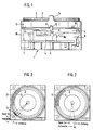
- the time switch module 1 carries a switching disk 2 with switching tabs 3.
- this slide switch In cooperation with a switching lever 5, which performs the normal time switch function in the time switch module by scanning the switching rider 3 on the inside thereof, this slide switch has to perform three switching functions.
- the time switch In its left switch position, the time switch is constantly switched on regardless of the actuation of the switch tabs, in the middle switch position, as shown, the function of the time switch is dependent on the position of the switch tabs and in the right switch position, the time switch is independent of the position of the switch tabs , constantly switched off.
- the slide switch 4 runs in a groove 6 in a plate 7, which is the base plate of the timer module.
- a fastening piece 8 is provided, which serves for further guiding the slide switch 4 and has a leading edge 8a, on which the slide switch 4 comes into contact with a corresponding oblique edge 4a in its right switching position.
- the slide switch 4 rests on a housing wall 10 with a limiting pin 9.
- the slide switch 4 finally carries a switching cam 11, which comes into engagement with a groove 12 in a pot-shaped switching ring 13.
- This switching ring 13 is inserted between the switching disk 2 and the module housing 1 during the assembly of the timer module and encompasses the switching disk 2 concentrically, as shown in FIG. 2 can be seen.
- the switching ring 13 finally carries an actuating lug 14 which can be rotated with the switching ring into the three switching positions shown in FIG. 2.
- the switching ring 13 finally carries a further groove 15, which is used so that the switching ring 13 can also be used in the mounting position according to FIG. 3.
- the groove 15 interacts with the switch cam 11 instead of the groove 12.
- cup-shaped switching ring is shown in a view from above without a switching disc. It can be seen that several openings are provided in its bottom area, which serve to enable the switching lever 5 and possibly further assemblies of the time switch module to pass through to the switching disk.
Description
Die Neuerung bezieht sich auf einen Schalter für einen Schaltuhrmodul mit einer Schaltscheibe, die am Umfang angeordnete Schaltreiter trägt und mit einem Schalthebel zum Abtasten der Schaltreiter von der Innenseite der Schaltscheibe, wobei der Schalter aus einem Befestigungsstück und einem an diesem in mehrere Schaltstellungen quer zur Auslenkrichtung des Schalthebels bewegbaren Schaltschieber besteht, am Rahmen des Schaltuhrmoduls befestigt ist und mit dem Schalthebel zusammenwirkt. Die Neuerung geht aus von einem Schalter der vorbezeichneten Art, wie er in der DE-OS 37 43 214 der Anmelderin beschrieben ist. Der dort näher erläuterte Schalter ist an einem Schaltuhrmodul wahlweise anbaubar. Zur Betätigung des dort beschriebenen Schaltschiebers dient eine Betätigungsnase, welche seitlich am Schaltuhrmodul parallel zu einer Begrenzungskante in drei Schaltstellungen verschiebbar ist.The innovation relates to a switch for a time switch module with a switching disk that carries switching riders arranged on the circumference and with a switching lever for scanning the switching riders from the inside of the switching disk, the switch consisting of a fastening piece and one on it in several switching positions transverse to the deflection direction of the shift lever movable slide switch is attached to the frame of the timer module and interacts with the shift lever. The innovation is based on a switch of the aforementioned type, as described in DE-OS 37 43 214 of the applicant. The switch explained in more detail there can be optionally attached to a time switch module. An actuating lug is used to actuate the slide switch described there, which can be moved laterally on the time switch module parallel to a limiting edge in three switching positions.
Es hat sich nun gezeigt, daß bei dem Einbau des Schaltuhrmoduls in Installationsgeräte oder auch in Schaltuhren verschiedener räumlicher Ausgestaltung diese Betätigungsnase nicht immer griffgünstig liegt oder aus räumlichen Gründen des umgebenden Gehäuses an der aus baulichen Gründen notwendigen Stelle nicht günstig plaziert ist.It has now been shown that when the time switch module is installed in installation devices or also in time switches of various spatial configurations, this operating lug is not always within easy reach or is not conveniently placed at the location necessary for structural reasons due to the surrounding housing.
Es war nun Aufgabe der Neuerung, einen Schalter vorzuschlagen, welcher die Einsatzmöglichkeiten des Schaltuhrmoduls mit angebautem Schalter wesentlich erweitert.It was now the task of the innovation to propose a switch that significantly expanded the possible uses of the timer module with the switch attached.
Zu diesem Zwecke schlägt die Neuerung vor, daß die Schaltscheibe in einem topfförmigen Schaltring angeordnet ist, welcher zumindest eine Nut für die Aufnahme eines am Schaltschieber angeordneten Schaltnockens aufweist. Ein derartiger topfförmiger Schaltring, welcher bei der Montage des Schaltuhrmoduls zwischen das Modulgehäuse und die Schaltscheibe verdrehbar montiert wird, ermöglicht, die Betätigungsnase an einer beliebigen Stelle des Schaltrings, welcher konzentrisch die Schaltscheibe umgibt, anzuordnen. Der Eingriff dieses in drei Schaltstellungen verdrehbaren Schaltrings in den sich längs geradlinig verschiebenden Schaltschieber erfolgt durch eine Nut, welche mit einem Nocken auf dem Schaltschieber zusammenwirkt. Je nach Einbauerfordernis kann der topfförmige Schaltring bei der Montage in verschiedene Stellungen montiert werden. Damit der jeweilige Eingriff der Nut mit dem Schaltnocken gegeben ist, trägt der Schaltring daher vorzugsweise mehrere Nuten an vorbestimmten Stellen, so daß je nach Anordnung des Schaltrings wahlweise eine dieser Nuten mit dem Schaltnocken in Eingriff kommt.For this purpose, the innovation proposes that the switching disk is arranged in a pot-shaped switching ring which has at least one groove for receiving a switching cam arranged on the switching slide. Such a pot-shaped switching ring, which is rotatably mounted during assembly of the timer module between the module housing and the switching disk, makes it possible to arrange the actuating lug at any point on the switching ring which concentrically surrounds the switching disk. The engagement of this switching ring, which can be rotated in three switching positions, in the linearly shifting slide switch takes place through a groove which interacts with a cam on the slide switch. Depending on the installation requirements, the pot-shaped switching ring can be installed in different positions during installation. So that the respective engagement of the groove with the switching cam is given, the switching ring therefore preferably carries a plurality of grooves at predetermined locations, so that, depending on the arrangement of the switching ring, one of these grooves optionally comes into engagement with the switching cam.
Weitere Merkmale der Neuerung sind in den Unteransprüchen gekennzeichnet.Further features of the innovation are characterized in the subclaims.
Nachfolgend soll die Neuerung anhand der Zeichnung an einem Ausführungsbeispiel noch näher erläutert werden.The innovation is to be explained in more detail below with reference to the drawing using an exemplary embodiment.
Es zeigen:
- Figur 1
- den Schalter, angebaut an den Schaltuhrmodul, in einer Seitenansicht;
Figur 2- den Schaltuhrmodul in schematisierter Ansicht von oben in einer ersten Montagestellung des Schaltrings;
Figur 3- die gleiche Darstellung wie
Figur 2 mit einer zweiten Montagestellung des Schaltrings; Figur 4- den Schaltring in einer Ansicht von oben;
- Figur 5
- den Schaltring in einem Schnitt von der Seite.
- Figure 1
- the switch, attached to the timer module, in a side view;
- Figure 2
- the timer module in a schematic view from above in a first mounting position of the switching ring;
- Figure 3
- the same representation as Figure 2 with a second mounting position of the shift ring;
- Figure 4
- the switching ring in a view from above;
- Figure 5
- the switching ring in a cut from the side.
In Figur 1 trägt der Schaltuhrmodul 1 eine Schaltscheibe 2 mit Schaltreitern 3. Unterhalb der Schaltscheibe ist ein in drei Schaltstellungen in der Zeichenebene verschiebbarer Schaltschieber 4 angeordnet, welcher in seiner mittleren Schaltstellung dargestellt ist. Dieser Schaltschieber hat im Zusammenwirken mit einem Schalthebel 5, welcher in dem Schaltuhrmodul die normale Schaltuhrfunktion durch Abtastung der Schaltreiter 3 an deren Innenseite bewerkstelligt, drei Schaltfunktionen auszuführen. In seiner linken Schaltstellung ist die Schaltuhr unabhängig von der Betätigung der Schaltreiter ständig eingeschaltet, in der mittleren Schaltstellung, wie dargestellt, ist die Funktion der Schaltuhr abhängig von der Stellung der Schaltreiter und in der rechten Schaltstellung ist die Schaltuhr, unabhängig von der Stellung der Schaltreiter, ständig ausgschaltet.In FIG. 1, the time switch module 1 carries a
Der Schaltschieber 4 läuft in einer Nut 6 in einer Platte 7, welche die Grundplatte des Schaltuhrmoduls darstellt. Auf dieser ist ein Befestigungsstück 8 vorgesehen, welches zur weiteren Führung des Schaltschiebers 4 dient und eine Auflaufkante 8a besitzt, auf welcher der Schaltschieber 4 in seiner rechten Schaltstellung mit einer entsprechenden schrägen Kante 4a zur Anlage kommt. In seiner linken Schaltstellung liegt der Schaltschieber 4 mit einem Begrenzungsstift 9 an einer Gehäusewand 10 an. Der Schaltschieber 4 trägt schließlich noch einen Schaltnocken 11, welcher in Eingriff mit einer Nut 12 in einem topfförmigen Schaltring 13 kommt. Dieser Schaltring 13 wird bei dem Montageaufbau des Schaltuhrmoduls zwischen die Schaltscheibe 2 und dem Modulgehäuse 1 eingelegt und umfaßt die Schaltscheibe 2 konzentrisch, wie aus der Figur 2 gut ersichtlich ist. Zur Ausführung der Schaltfunktion trägt der Schaltring 13 schließlich eine Betätigungsnase 14, welche mit dem Schaltring in die in Figur 2 dargestellten drei Schaltstellungen verdrehbar ist.The
Der Schaltring 13 trägt schließlich eine weitere Nut 15, die dazu dient, daß der Schaltring 13 auch in der Montagestellung gemäß Figur 3 eingesetzt werden kann. In diesem Falle wirkt die Nut 15 anstelle der Nut 12 mit dem Schaltnocken 11 zusammen.The
In Figur 4 ist der topfförmige Schaltring in einer Ansicht von oben ohne Schaltscheibe dargestellt. Man erkennt, daß in seinem Bodenbereich mehrere Öffnungen vorgesehen sind, die dazu dienen, den Durchtritt des Schalthebels 5 und gegebenenfalls weiterer Baugruppen des Schaltuhrmoduls zur Schaltscheibe zu ermöglichen.In Figure 4, the cup-shaped switching ring is shown in a view from above without a switching disc. It can be seen that several openings are provided in its bottom area, which serve to enable the switching lever 5 and possibly further assemblies of the time switch module to pass through to the switching disk.
In Figur 5 ist der topfförmige Schaltring schließlich noch in einer Schnittdarstellung von der Seite gesehen gezeichnet.In Figure 5, the cup-shaped switching ring is finally drawn in a sectional view seen from the side.
Claims (4)
- Switch for a timer module (1) with an indexing disc (2), which bears riders (3) arranged on its periphery, and with a switch lever (5) for scanning the riders (3) from the inside of the indexing disc (2), said switch comprising a fastening part and a slide (4), which may be moved obliquely to the direction of deflection of the switch lever on said fastening part into several switching positions, is secured to the frame of the timer module and cooperates with the switch lever (5), characterised in that the indexing disc (2) is arranged in a cup-shaped switching ring (13), which has at least one groove (12) to receive a trigger cam (11) arranged on the slide (4).
- Switch according to Claim 1, characterised in that the cup-shaped switching ring (13) has two grooves (12 and 15) offset at approximately 45° on the periphery to selectively receive the trigger cam (11) and may accordingly be mounted at an angle of approximately 45° in relation to the indexing disc (2).
- Switch according to Claim 1 or 2, characterised in that the cup-shaped switching ring (13) has openings (16) in its base area for the switch lever (5) to pass through and optionally has further structural components.
- Switch according to Claim 1, characterised in that the cup-shaped switching ring (13) has a control lug (14) on its ring surface.
Applications Claiming Priority (2)
| Application Number | Priority Date | Filing Date | Title |
|---|---|---|---|
| DE8911155U DE8911155U1 (en) | 1989-09-19 | 1989-09-19 | |
| DE8911155U | 1989-09-19 |
Publications (3)
| Publication Number | Publication Date |
|---|---|
| EP0418637A2 EP0418637A2 (en) | 1991-03-27 |
| EP0418637A3 EP0418637A3 (en) | 1992-07-08 |
| EP0418637B1 true EP0418637B1 (en) | 1995-02-01 |
Family
ID=6842982
Family Applications (1)
| Application Number | Title | Priority Date | Filing Date |
|---|---|---|---|
| EP90116939A Expired - Lifetime EP0418637B1 (en) | 1989-09-19 | 1990-09-04 | Switch for a switch clock module |
Country Status (2)
| Country | Link |
|---|---|
| EP (1) | EP0418637B1 (en) |
| DE (2) | DE8911155U1 (en) |
Families Citing this family (2)
| Publication number | Priority date | Publication date | Assignee | Title |
|---|---|---|---|---|
| ES2159982T3 (en) * | 1999-11-05 | 2001-10-16 | Orbis Tecnologia Electrica S A | ELECTRICAL CONNECTION WATCH. |
| DE10230454A1 (en) * | 2002-07-06 | 2004-01-22 | Diehl Ako Stiftung & Co. Kg | Electromechanical timer |
Family Cites Families (2)
| Publication number | Priority date | Publication date | Assignee | Title |
|---|---|---|---|---|
| DE3743214A1 (en) * | 1987-12-19 | 1989-06-29 | Diehl Gmbh & Co | ATTACHABLE SWITCH FOR A TIMER MODULE |
| DE8901269U1 (en) * | 1989-02-04 | 1989-04-27 | Graesslin Kg, 7742 St Georgen, De |
-
1989
- 1989-09-19 DE DE8911155U patent/DE8911155U1/de not_active Expired - Lifetime
-
1990
- 1990-09-04 DE DE59008406T patent/DE59008406D1/en not_active Expired - Fee Related
- 1990-09-04 EP EP90116939A patent/EP0418637B1/en not_active Expired - Lifetime
Also Published As
| Publication number | Publication date |
|---|---|
| DE59008406D1 (en) | 1995-03-16 |
| EP0418637A3 (en) | 1992-07-08 |
| EP0418637A2 (en) | 1991-03-27 |
| DE8911155U1 (en) | 1991-01-24 |
Similar Documents
| Publication | Publication Date | Title |
|---|---|---|
| DE2810609C3 (en) | Control switches, in particular for play equipment for manipulating image patterns on a screen | |
| DE1790340A1 (en) | TIMER | |
| EP0623942A1 (en) | Encoder | |
| DE3613702C2 (en) | ||
| DE4117303C2 (en) | Horn control insert for a steering wheel | |
| DE4443726A1 (en) | Multidirectional input switch | |
| EP0418637B1 (en) | Switch for a switch clock module | |
| DE3508110C2 (en) | ||
| DE1911104C3 (en) | Electrical snap switch | |
| DE1281529B (en) | Multiple contact switch | |
| EP0319831B1 (en) | Vacuum cleaner with a one-piece push button | |
| DE2240482C3 (en) | Limit switch | |
| EP0856863B1 (en) | Pivotable actuator for a safety switch | |
| DE2426054A1 (en) | DEVICE FOR ACTIVATING THREE BREAKERS WITH THE HELP OF TWO PUSH BUTTONS | |
| DE19923722C1 (en) | Contact device for stepping switch pre-selector has contact ring within pre-selector insulating housing cooperating with contact secured in bore in housing wall via positioning washer mounted on contact shaft | |
| DE2416152A1 (en) | CIRCUIT BREAKER | |
| DE3228469A1 (en) | Device for position indication on switching devices | |
| EP0827167A1 (en) | Electric switch particularly for vehicles | |
| DD270404A1 (en) | KEYPAD FOR WRITING AND COMPUTER TECHNOLOGY | |
| EP0450319B1 (en) | Push-button switch | |
| DE2911252C2 (en) | Snap switch with contact bridges | |
| EP0303159B1 (en) | Spreader for an electric contact assembly | |
| DE2727717C3 (en) | Slide button | |
| DE2615480C3 (en) | Switching device | |
| DE8235148U1 (en) | Mechanical control device for electrical contact arrangements, especially for switching timing devices |
Legal Events
| Date | Code | Title | Description |
|---|---|---|---|
| PUAI | Public reference made under article 153(3) epc to a published international application that has entered the european phase |
Free format text: ORIGINAL CODE: 0009012 |
|
| AK | Designated contracting states |
Kind code of ref document: A2 Designated state(s): DE FR GB IT |
|
| PUAL | Search report despatched |
Free format text: ORIGINAL CODE: 0009013 |
|
| AK | Designated contracting states |
Kind code of ref document: A3 Designated state(s): DE FR GB IT |
|
| 17P | Request for examination filed |
Effective date: 19930311 |
|
| 17Q | First examination report despatched |
Effective date: 19940628 |
|
| GRAA | (expected) grant |
Free format text: ORIGINAL CODE: 0009210 |
|
| AK | Designated contracting states |
Kind code of ref document: B1 Designated state(s): DE FR GB IT |
|
| REF | Corresponds to: |
Ref document number: 59008406 Country of ref document: DE Date of ref document: 19950316 |
|
| GBT | Gb: translation of ep patent filed (gb section 77(6)(a)/1977) |
Effective date: 19950323 |
|
| ITF | It: translation for a ep patent filed |
Owner name: STUDIO JAUMANN |
|
| ET | Fr: translation filed | ||
| PLBE | No opposition filed within time limit |
Free format text: ORIGINAL CODE: 0009261 |
|
| STAA | Information on the status of an ep patent application or granted ep patent |
Free format text: STATUS: NO OPPOSITION FILED WITHIN TIME LIMIT |
|
| 26N | No opposition filed | ||
| PGFP | Annual fee paid to national office [announced via postgrant information from national office to epo] |
Ref country code: GB Payment date: 19990824 Year of fee payment: 10 |
|
| PGFP | Annual fee paid to national office [announced via postgrant information from national office to epo] |
Ref country code: FR Payment date: 19990929 Year of fee payment: 10 |
|
| PGFP | Annual fee paid to national office [announced via postgrant information from national office to epo] |
Ref country code: DE Payment date: 19991013 Year of fee payment: 10 |
|
| PG25 | Lapsed in a contracting state [announced via postgrant information from national office to epo] |
Ref country code: GB Free format text: LAPSE BECAUSE OF NON-PAYMENT OF DUE FEES Effective date: 20000904 |
|
| GBPC | Gb: european patent ceased through non-payment of renewal fee |
Effective date: 20000904 |
|
| PG25 | Lapsed in a contracting state [announced via postgrant information from national office to epo] |
Ref country code: FR Free format text: LAPSE BECAUSE OF NON-PAYMENT OF DUE FEES Effective date: 20010531 |
|
| PG25 | Lapsed in a contracting state [announced via postgrant information from national office to epo] |
Ref country code: DE Free format text: LAPSE BECAUSE OF NON-PAYMENT OF DUE FEES Effective date: 20010601 |
|
| REG | Reference to a national code |
Ref country code: FR Ref legal event code: ST |
|
| PGFP | Annual fee paid to national office [announced via postgrant information from national office to epo] |
Ref country code: IT Payment date: 20060930 Year of fee payment: 17 |
|
| PG25 | Lapsed in a contracting state [announced via postgrant information from national office to epo] |
Ref country code: IT Free format text: LAPSE BECAUSE OF NON-PAYMENT OF DUE FEES Effective date: 20070904 |