EP0418088A2 - Plate adjusting mechanism for leaf-type printing machine - Google Patents
Plate adjusting mechanism for leaf-type printing machine Download PDFInfo
- Publication number
- EP0418088A2 EP0418088A2 EP90310052A EP90310052A EP0418088A2 EP 0418088 A2 EP0418088 A2 EP 0418088A2 EP 90310052 A EP90310052 A EP 90310052A EP 90310052 A EP90310052 A EP 90310052A EP 0418088 A2 EP0418088 A2 EP 0418088A2
- Authority
- EP
- European Patent Office
- Prior art keywords
- plate
- slider
- clamping means
- moving shaft
- top side
- Prior art date
- Legal status (The legal status is an assumption and is not a legal conclusion. Google has not performed a legal analysis and makes no representation as to the accuracy of the status listed.)
- Granted
Links
- 230000007246 mechanism Effects 0.000 title claims abstract description 34
- 238000000034 method Methods 0.000 description 11
- 230000002093 peripheral effect Effects 0.000 description 3
- 239000003086 colorant Substances 0.000 description 2
- 238000010276 construction Methods 0.000 description 2
- 230000000694 effects Effects 0.000 description 2
- 238000010586 diagram Methods 0.000 description 1
- 238000006073 displacement reaction Methods 0.000 description 1
- 230000002349 favourable effect Effects 0.000 description 1
- 235000015250 liver sausages Nutrition 0.000 description 1
- 238000002360 preparation method Methods 0.000 description 1
Images

Classifications
-
- B—PERFORMING OPERATIONS; TRANSPORTING
- B41—PRINTING; LINING MACHINES; TYPEWRITERS; STAMPS
- B41F—PRINTING MACHINES OR PRESSES
- B41F27/00—Devices for attaching printing elements or formes to supports
- B41F27/005—Attaching and registering printing formes to supports
-
- B—PERFORMING OPERATIONS; TRANSPORTING
- B41—PRINTING; LINING MACHINES; TYPEWRITERS; STAMPS
- B41F—PRINTING MACHINES OR PRESSES
- B41F27/00—Devices for attaching printing elements or formes to supports
- B41F27/12—Devices for attaching printing elements or formes to supports for attaching flexible printing formes
- B41F27/1218—Devices for attaching printing elements or formes to supports for attaching flexible printing formes comprising printing plate tensioning devices
- B41F27/1225—Devices for attaching printing elements or formes to supports for attaching flexible printing formes comprising printing plate tensioning devices moving in the printing plate end substantially rectilinearly
- B41F27/1231—Devices for attaching printing elements or formes to supports for attaching flexible printing formes comprising printing plate tensioning devices moving in the printing plate end substantially rectilinearly by translatory motion substantially tangential to support surface
-
- B—PERFORMING OPERATIONS; TRANSPORTING
- B41—PRINTING; LINING MACHINES; TYPEWRITERS; STAMPS
- B41P—INDEXING SCHEME RELATING TO PRINTING, LINING MACHINES, TYPEWRITERS, AND TO STAMPS
- B41P2227/00—Mounting or handling printing plates; Forming printing surfaces in situ
- B41P2227/40—Adjusting means for printing plates on the cylinder
- B41P2227/43—Adjusting means for printing plates on the cylinder diagonally
Definitions
- This invention relates to a plate clamping apparatus for a leaf-type printing machine, and more particularly, to a mechanism for shifting a plate wrapped around a plate roller of a printing machine for adjusting the position of the plate so as to eliminate shears in printing.
- plates In a multiple colour leaf-type printing machine, which prints multiple colours on a single leaf of paper, plates should be wrapped around respective plate rollers with as little relative displacement as possible so that the patterns printed by respective printing units coincide such that elegant printed matter can be obtained.
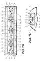
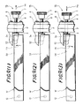
- a plate clamping apparatus of a conventional leaf-type printing machine for example as shown in Figures 1 (1) and 1 (2), is accommodated in a recess 29 formed in the axial direction of a plate roller P and comprises as its main component a top side plate clamp W, a bottom side plate clamp S and a plate stretcher for stretching a plate Y wrapped around the plate roller P.
- the plate Y is attached to thus constructed conventional plate clamping apparatus as follows: First, flat surfaces of a top side cam shaft 51 and a bottom side cam shaft 55 are directed upwardly by a tool which is applied at tool locations 28a and 28b, whereby the tip of top side upper teeth 53 and bottom side upper teeth 57 are lifted and opened by urging force of springs 36 and 37, with spherically headed bolts 25a and 25b as fulcrums.
- the plate roller P When clamping of the top end of the plate Y by the top side plate clamp W is completed, the plate roller P is rotated, as the plate Y is closely contacted to the peripheral surface of the plate roller P, to a position where the bottom end of the plate Y can be easily attached to the bottom side plate clamp S. At this position, the bottom end of the plate Y is inserted between the bottom side upper teeth 57 and bottom side lower teeth 58, and the bottom side cam shaft 55 is rotated by manual operation to close the bottom side upper teeth 57 and accordingly clamp the bottom end of the plate Y.
- the plate stretching cam shaft 59 is rotated by a tool, which is applied at a tool location 28c provided in an end portion of the cam shaft 59, to move the bottom side clamp S away from the bottom side lateral wall 56, whereby the plate Y is stretched and closely contacted to the peripheral surface of the plate roller P.
- the mounting procedure is completed.
- removal of the plate Y may be achieved by reversely performing the above-mentioned mounting procedure.
- a shear in the vertical direction i.e., a transporting direction of paper is eliminated by adjusting respective fine adjustment bolts 62a, 62b, 62c, 62d, 62e, 62f, 62g and 62h.
- a shear in the horizontal direction i.e., the direction perpendicular to the paper transporting direction, is eliminated by rotating adjusting bolts 61a, 61b, 61c and 61d for the top and bottom sides.
- the adjusting bolt 61a on the top side is rotated to form a gap between the head of the adjusting bolt 61a and a lateral wall of the plate roller P.
- the top side plate clamp W is moved toward left by a necessary amount.
- the adjusting bolt 61a is rotated until its head comes into contact with the lateral wall of the plate roller P, whereby the movement of the top side plate clamp W toward left is terminated. Movement of the top side plate clamp W in the left or right direction is limited by the adjusting bolts 61a and 61b, the heads of which are in contact with one and the other lateral sides of the plate roller P.
- the adjusting bolts 61a, 61b, 61c and 61d are rotated to form a narrow gap between the head of the respective adjusting bolts and the side wall of the recess 29 of the plate roller P.
- the fine adjustment bolts 62e, 62f, 62g and 62h on the bottom side are rotated to bring the bottom side plate clamp S close to the bottom side lateral wall 56, whereby the left side gap portion becomes wider while the right side gap portion becomes very narrow.
- the fine adjustment bolts 62a, 62b, 62c and 62d on the top side are respectively rotated such that the top side plate clamp S is moved away from the top side lateral wall 52, whereby the left side gap becomes wider while the right side gap becomes very narrow.
- the fine adjustment bolts are rotated in a manner that the top side plate clamp W is moved by the amount by which the bottom side plate clamp S was brought close to the bottom side lateral wall 56, thereby making it possible to shift the plate Y for adjustment.
- the fine adjustment bolts 62a, 62b, 62c and 62d are rotated in the opposite direction to bring the heads of the respective fine adjustment bolts into contact with the side wall of the recess 29 of the plate roller P to limit lateral movement of the plate clamps S and W, thus terminating a shifting procedure for the plate Y in one direction. It will be understood that a shift of the plate Y in the opposite direction can be also achieved in the same manner as explained above.
- the present invention provides a plate adjusting mechanism for a leaf-type printing machine comprising a top side plate clamping means and a bottom side plate clamping means, characterized in that a side end portion of one of said clamping means is rotatable to adjust the position of a plate.
- Figures 2 (1) and 2 (2) show a plate shifting mechanism of one embodiment incorporated in a plate clamping apparatus of an otherwise conventional leaf-type printing machine.
- the plate clamping apparatus provided with the plate shifting mechanism is formed of a top side plate clamp W, a bottom side plate clamp S and a plate stretcher, that is, it basically has the same structure as the conventional apparatus as shown in Figure 1.
- the plate clamping apparatus of Figure 2 does not have adjusting bolts 61a, 61b, 61c and 6Id and fine adjustment bolts 62a, 62b, 62c, 62d, 62e, 62f, 62g and 62h, as does the conventional plate clamping apparatus of Figure 1.
- the position of a plate Y is not adjusted by these adjusting bolts and fine adjustment bolts but by a plate shifting mechanism.
- the top side plate clamp W is provided with top side upper teeth 53, divided into four portions, and top side lower teeth 54, between which are interposed a spring 36 and a top side cam shaft 51.
- a tool location 28a is mounted at a substantially central portion of the top side cam shaft 51.
- These top side upper teeth 53, top side lower teeth 54 and top side cam shaft 51 are assembled by a spherically headed bolt 25a.
- the bottom side plate clamp S is provided with bottom side upper teeth 57, divided into four portions, and bottom side lower teeth 58, between which a spring 37 and a bottom side cam shaft 55 are interposed. Also, a tool location 28b is mounted on the bottom side cam shaft 55. These bottom side upper teeth 57, bottom side lower teeth 58 and bottom side cam shaft 55 are assembled by a spherically headed bolt 25b, in the same manner as the top side clamp W.
- a plate stretcher is provided with a plate stretching cam shaft 59 between the bottom side lower teeth 58 of the bottom side plate clamp S and a U-shaped groove of the plate roller P.
- the cam shaft 59 includes a notch in which a spring 63 is arranged between the top side lower teeth 54 and the bottom side lower teeth 58.
- the plate stretching cam shaft 59 is supported by the side wall of the plate roller P, and at one end thereof a tool location 28c is mounted while at the other end thereof a washer 35 is fixed by a cap bolt 24.
- the plate stretcher cam shaft 59 is therefore restricted in its movement in the axial direction by the tool location 28c and the washer 35.
- the plate stretcher cam shaft 59 is arranged to be rotatable by a tool applied at the tool location 28c.
- the plate shifting mechanism 1 for adjusting the position of a plate is mounted in the vicinity of the adjusting bolt 61b of the top side plate clamp W as shown in Figure 1.
- One end portion of the mechanism 1 is pivoted such that the adjustment of a plate, which has been conventionally carried out by the adjusting bolt 61b in the conventional plate clamping apparatus, is performed by pivoting movement of the mechanism 1.
- top side plate clamp W (the left side in Figure 2 (1)) is pivoted by a fulcrum pin 12, and the plate shifting mechanism 1 mounted on the right side is operated, whereby the right side portion of the top side plate clamp W only is pivoted on the fulcrum pin 12 in the vertical direction, as shown in Figure 2 (1), to thereby adjust the position of the plate Y.
- a gear 7 is inversely rotated, whereby a slider 3 of a moving shaft 2 is returned to the previous position, and therefore the top side lower teeth 54 is automatically returned by means of an urging force of a spring 63 as shown in Figure 2.
- FIG 3 is an enlarged cross-sectional view showing a main portion of the plate shifting mechanism 1 for adjusting the plate position.
- the plate shifting mechanism 1 comprises the slider moving shaft 2 mounted on the plate roller P through a bearing 4.
- the slider 3 having a sloping surface 3a is attached to the moving shaft 2 and arranged in one side end portion (the right side in Figure 3) of the top side plate clamp W, i.e. in the top side lower teeth 54.
- a gear 7 is mounted on the slider moving shaft 2 by a taper pin 6.
- the slider moving shaft 2 When the gear 7 is rotated, the slider moving shaft 2 is axially moved by a threaded portion 5 of the bearing 4.
- the ball bearing 10 is attached to the top side lower teeth 54 by a ball bearing pin 11.
- the ball bearing 10 is provided for reducing a slide resistance between the top side plate clamp W and the slider 3 and therefore smoothly rotating the top side plate clamp W when the top side plate clamp W is pivoted on the pin 12, in response to advancing and retreating movement of the slider 3.
- rotation of the gear 7 causes the slider moving shaft 2 to advance or retreat and accordingly the slider 3 in contact with the ball bearing 10 to advance or retreat, whereby the ball bearing 10 is rotated along the sloping surface 3a of the slider 3, and also the top side plate clamp W is pivoted on the pin 12 (see Figure 2 (1)) by the sloping surface 3a against or by means of an urging force of the spring 63. Consequently, the other end of the top side plate clamp W is moved vertically in Figure 2 (1).
- the slider 3 has a stopping ring 9 which prevents the slider 3 from coming off the slider moving shaft 2.
- the bearing 4 is fixed to the plate roller P by bolts 8.
- Figure 4 (1) is an enlarged cross-sectional view of a main portion of the plate clamping apparatus of Figure 2, taken along a line A - A drawn in Figure 2 (1).
- the plate shifting mechanism 1 is arranged in a portion of the top side lower teeth 54.
- the ball bearing 10 is arranged in the top side lower teeth 54, fixed by the ball bearing fixing pin 11 which in turn is secured by a bolt 5′.
- Figure 4 (2) is a cross-sectional view taken along a line drawn B - B in Figure 2 (1).
- the top side lower teeth 54 are pivotably supported on the bottom surface of the recess 29 of the plate roller P by the fulcrum pin 12.
- the bottom side lower teeth 58 are provided with a spring guide pin 34 through a spring receiving collar 41.
- a spring 26 is interposed between the spring receiving collar 41 and the bottom side lower teeth 58 for preventing the plate Y from being excessively stretched.
- Figure 4 (3) is a cross-sectional view taken along a line C - C drawn in Figure 2 (1) which shows a section for adjusting the bottom side plate clamp S in the axial direction of the plate roller P.
- An adjusting bolt 44 is provided through a receiving pate 43 on the outer wall of the plate roller P.
- a threaded portion of the adjusting bolt 44 is meshed with the bottom side lower teeth 58.
- a spring 27 and a washer 45 are interposed between the bottom side lower teeth 58 and the receiving plate 43.
- Figure 4 (4) is a cross-sectional view taken along a line D - D drawn in Figure 2 (1) and shows a section for preventing the top and bottom side plate clamps W and S from coming off the recess 29 of the plate roller P and also for restricting movement thereof in the recess 29.
- notches 42 and 42a are formed in the top side and bottom side lower teeth 54 and 58, respectively, and guide plates 23 and 23a are disposed in the notches 42 and 42a and fixed by bolts 30, 30a, respectively.
- a guide plate 23b which is arranged to slide along the guide plates 23 and 23a is mounted on the bottom surface of the recess 29 by a bolt 30b.
- the plate Y is wrapped around the plate roller P, and after other preparations for printing are completed, a trial printing is performed. If the result of this trial printing shows that the plate Y should be adjusted, the plate Y is shifted as the following procedure.
- the leaf-type printing machine is stopped, and one or more printing units which need adjustment of the plate Y are subjected to such adjustment.
- the plate stretching cam shaft 59 is rotated in the direction in which the plate Y is loosened, and the bottom side cam shaft 55 is also rotated to open the bottom side upper teeth 57.
- the upper teeth 57 of the bottom side plate clamp S only is opened to release the plate Y while the top side plate clamp W keeps clamping the plate Y on a Y1 side ( Figure 2 (2)). This is because the whole plate Y can be moved without difficulty, as shown in Figure 2 (2).
- a rotating direction of the gear 7 is determined by a direction in which the plate Y is to be shifted.
- the moving shaft 2 On rotating the gear 7 in the thus determined direction, the moving shaft 2 is moved by the threaded portion 5 of the bearing 4 in a direction indicated by an arrow H: in Figure 5 (1), say.
- the slider 3 As the moving shaft 2 is moved, the slider 3 is also moved in the same direction. Since the sloping surface 3a of the slider 3 and the ball bearing 10 are always in contact with each other by an urging force of the spring 63, the ball bearing 10 smoothly runs on the sloping surface 3a by the movement of the slider 3. Therefore, the top side lower teeth 54 are moved in a direction indicated by an arrow H2 by an urging force of the spring 63, with the fulcrum pin 12 being the centre of movement. Consequently, the plate Y is shifted based on the left side thereof shown in Figure 5 (1).
- the adjustment procedure is completed by shifting the plate Y by a predetermined amount as described above.
- the plate roller P and an associated bracket roller (not shown) are led to a printing condition.
- the leaf-type printing machine is operated to rotate several times the plate roller P being in contact with the bracket roller, so as to bring the plate Y, the position adjusted in the aforementioned manner, closely into contact with the peripheral surface of the plate roller P.
- the bottom side plate clamp S is positioned in the vicinity of the contact point of the plate roller P and the bracket roller, the operation of the plate roller P and the bracket roller, the operation of the leaf-type printing machine is stopped.
- the bottom side cam shaft 55 is rotated to close the bottom side upper teeth 57 and clamp the plate Y.
- the plate stretching cam shaft 59 is rotated to stretch the plate Y, and the plate roller P is released from the contact with the bracket roller, thus completing the plate adjustment procedure.
- the plate P can be shifted for adjustment only by vertically moving one side portion of the top side plate clamp by a manual or automatic operation of the gear 7.
- Such a mechanism can eliminate complicated and time-consuming manual operations of both the top and bottom side plate clamps W and S, as is required for adjustment of the plate Y in conventional leaf-type printing machines.
- a driving apparatus not shown
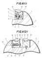
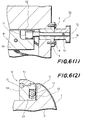
- FIGS 6 (1) and (2) and 7 (1) - (3) show a second embodiment of the present invention.
- a plate shifting mechanism 70 differs from the above described first embodiment in that the second embodiment does not employ the ball bearing 10, the ball bearing pin 11, the stopper bolt 5′, the slider 3 and the stopping ring 9, and comprises a plate clamp moving shaft 72 having an eccentric portion 7I, rotatably arranged on the side wall of the plate roller P, in place of the slider moving shaft 2.
- the eccentric portion 71 is contacted with one side end portion of the top side plate clamp W.
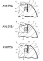
- FIG. 7 (1) - 7 (3) show such pivoting movement of the top side plate clamp W.
- Figure 7 (1) - (3) show that the one side end portion of the top side plate clamp W is at the position most close to the side wall 52, at an intermediate position, and at the position furthest from the side wall 52, respectively.
- the other structure and operations of the second embodiment are identical to the first embodiment shown in Figures 2 - 5, so that the parts in Figures 6 and 7 corresponding to those in Figures 2 - 5 are designated the same reference numerals and detailed explanation thereof will be omitted.
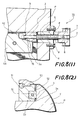
- FIGS 8 (2), 8 (2) and 9 (1) - 9 (3) show a third embodiment of the present invention, in which a plate shifting mechanism 75 differs from the first embodiment shown in Figures 2 - 5 in that the third embodiment does not employ the ball bearing 10, the ball bearing pin 11 and the stopper bolt 5′ and comprises a sloping surface 76 substantially equal to the sloping surface 3a of the slider 3 on the top side lower teeth 54 of the top side plate clamp W.
- the sloping surface 76 is in contact with the sloping surface 3a of the slider 3.
- the other structure and operations of the third embodiment are identical to the first embodiment shown in Figures 2 - 5, so that the parts in Figures 8 and 9 corresponding to those in Figures 2 - 5 are designated the same reference numerals and detailed explanation thereof will be omitted.
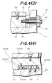
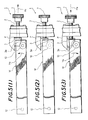
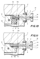
- FIG 10 shows a fourth embodiment of the present invention.
- a plate shifting mechanism 72 of Figure 10 differs from the first embodiment shown in Figures 2 - 5 in that the bearing 4 does not have the threaded portion 5 and a slider moving shaft 78 is arranged to rotatably slide in the bearing 4.
- the slider moving shaft 78 is rotatably engaged with a threaded portion 79a of a slider 79, so as to solely advance and retreat the slider 79.
- the slider 79 is in contact with the ball bearing 10.
- the gear 7, fixed to the slider moving shaft 78 by a taper pin 80 is rotated to advance and retreat in the axial direction, whereby the top side plate clamp W is pivoted on the fulcrum pin 12.
- the rest of construction and operations of the fourth embodiment are the same as those of the first embodiment shown in Figures 2 - 5, so that the corresponding parts in Figure 10 are designated the same reference numerals and detailed explanation thereof will be omitted.
- Figure 11 shows a fifth embodiment of the present invention.
- a plate shifting mechanism 81 of Figure 11 differs from the fourth embodiment of Figure 10 in that the ball bearing 10 and the ball bearing pin 11 are not employed, and a sloping surface 82, substantially identical to the sloping surface 79b of the slider 79, is provided in the top side lower teeth 54 of the top side plate clamp W, the sloping surface 82 being in contact with the sloping surface 79b of the slider 79.
- the rest of the construction and operations of the fifth embodiment are the same as those of the fourth embodiment, so that the corresponding parts in Figure 11 are designated the same reference numerals and detailed explanation thereof will be omitted.
- the fulcrum pin 12 is positioned in one end portion of the top side plate clamp W in the above embodiments, however, its position is not limited thereto, and the fulcrum pin 12 may be positioned, e.g., in a longitudinal central portion of the top side plate clamp W.
- the plate shifting mechanisms 1, 70, 75, 77 and 81 are arranged in the top side plate clamp W in the above embodiments, however, they may be also arranged in the bottom side plate clamp S.
Abstract
Description
- This invention relates to a plate clamping apparatus for a leaf-type printing machine, and more particularly, to a mechanism for shifting a plate wrapped around a plate roller of a printing machine for adjusting the position of the plate so as to eliminate shears in printing.
- In a multiple colour leaf-type printing machine, which prints multiple colours on a single leaf of paper, plates should be wrapped around respective plate rollers with as little relative displacement as possible so that the patterns printed by respective printing units coincide such that elegant printed matter can be obtained.
- A plate clamping apparatus of a conventional leaf-type printing machine, for example as shown in Figures 1 (1) and 1 (2), is accommodated in a
recess 29 formed in the axial direction of a plate roller P and comprises as its main component a top side plate clamp W, a bottom side plate clamp S and a plate stretcher for stretching a plate Y wrapped around the plate roller P. - The plate Y is attached to thus constructed conventional plate clamping apparatus as follows: First, flat surfaces of a top
side cam shaft 51 and a bottomside cam shaft 55 are directed upwardly by a tool which is applied attool locations upper teeth 53 and bottom sideupper teeth 57 are lifted and opened by urging force ofsprings bolts stretching cam shaft 59 engages the ends of respectivefine adjustment bolts fine adjustment bolts stretching cam shaft 59, the bottom side plate clamp S is offset toward bottom sidelateral wall 56. Next, the plate roller P is rotated to a position at which the top end of the plate Y can be readily inserted between the top sideupper teeth 53 and top sidelower teeth 54 of the top side plate clamp W, and the topside cam shaft 51 is rotated by manual operation to close the top sideupper teeth 53 to thereby clamp the top end of the plate Y. When clamping of the top end of the plate Y by the top side plate clamp W is completed, the plate roller P is rotated, as the plate Y is closely contacted to the peripheral surface of the plate roller P, to a position where the bottom end of the plate Y can be easily attached to the bottom side plate clamp S. At this position, the bottom end of the plate Y is inserted between the bottom sideupper teeth 57 and bottom sidelower teeth 58, and the bottomside cam shaft 55 is rotated by manual operation to close the bottom sideupper teeth 57 and accordingly clamp the bottom end of the plate Y. Next, the platestretching cam shaft 59 is rotated by a tool, which is applied at atool location 28c provided in an end portion of thecam shaft 59, to move the bottom side clamp S away from the bottom sidelateral wall 56, whereby the plate Y is stretched and closely contacted to the peripheral surface of the plate roller P. Thus, the mounting procedure is completed. Incidentally, removal of the plate Y may be achieved by reversely performing the above-mentioned mounting procedure. - With the plate Y thus wrapped around the plate roller P, a trial printing is performed to examine shears in respective colours. A shear in the vertical direction, i.e., a transporting direction of paper is eliminated by adjusting respective
fine adjustment bolts bolts bolt 61a on the top side is rotated to form a gap between the head of the adjustingbolt 61a and a lateral wall of the plate roller P. Next, by rotating the adjustingbolt 61b on the top side with its head being in contact with the other lateral wall of the plate roller P, the top side plate clamp W is moved toward left by a necessary amount. After the movement of the necessary amount, the adjustingbolt 61a is rotated until its head comes into contact with the lateral wall of the plate roller P, whereby the movement of the top side plate clamp W toward left is terminated. Movement of the top side plate clamp W in the left or right direction is limited by the adjustingbolts - Next, a procedure for lowering the top left side of the plate Y of Figure 1 (1) will be explained. First, the adjusting
bolts recess 29 of the plate roller P. Next, thefine adjustment bolts lateral wall 56, whereby the left side gap portion becomes wider while the right side gap portion becomes very narrow. Then, thefine adjustment bolts lateral wall 52, whereby the left side gap becomes wider while the right side gap becomes very narrow. In other words, the fine adjustment bolts are rotated in a manner that the top side plate clamp W is moved by the amount by which the bottom side plate clamp S was brought close to the bottom sidelateral wall 56, thereby making it possible to shift the plate Y for adjustment. When the plate Y has been shifted as mentioned above, thefine adjustment bolts recess 29 of the plate roller P to limit lateral movement of the plate clamps S and W, thus terminating a shifting procedure for the plate Y in one direction. It will be understood that a shift of the plate Y in the opposite direction can be also achieved in the same manner as explained above. - For adjusting the position of a plate by shifting the same in the above-mentioned conventional plate clamping apparatus, however, complicated and time-consuming operations, such as fastening and loosening multiple fine adjustment bolts with a tool, are required. Also, since the adjustment procedure includes many steps, the operator should be well experienced in the adjustment. In addition, these operations are done in a small place and at a relatively elevated position, which does not allow the operations to be completed in a short time. Further, the adjustment, carried out by manual operation, does not make it possible to provide a high working efficiency and favourable adjustment effects.
- Viewed from one aspect the present invention provides a plate adjusting mechanism for a leaf-type printing machine comprising a top side plate clamping means and a bottom side plate clamping means, characterized in that a side end portion of one of said clamping means is rotatable to adjust the position of a plate.
- Some embodiments of the invention will now be described by way of example and with reference to the accompanying drawings, in which:-
- Figure 1 (1) is a plan view showing a conventional plate clamping apparatus for purpose of comparing with a apparatus shown in Figure 2 (1);
- Figure 1 (2) is a cross-sectional view taken along a line E - E of Figure 1 (1);
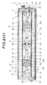
- Figure 2 (1) is a plan view showing a plate shifting mechanism according to an embodiment of the present invention mounted on a plate clamping apparatus of an otherwise conventional leaf-type printing machine;
- Figure 2 (2) is a side view showing how a plate is shifted;
- Figures 3 and 4 (1) - 4 (4) are partially enlarged cross-sectional views respectively showing a main portion of the mechanism according to the first embodiment of the present invention;
- Figures 5 (1) - 5 (3) are explanatory diagrams showing the operation of the plate clamping apparatus which employs an embodiment of the present invention;
- Figures 6 (1), 6 (2), 7 (1) - 7 (3) and 8 (1) - 8 (2) are cross-sectional views showing other embodiments of the present invention;
- Figures 9 (1) - 9 (3) are plan views showing operating conditions of another embodiment of the present invention; and
- Figures 10 and 11 are cross-sectional views showing other embodiments of the present invention.
- Figures 2 (1) and 2 (2) show a plate shifting mechanism of one embodiment incorporated in a plate clamping apparatus of an otherwise conventional leaf-type printing machine. The plate clamping apparatus provided with the plate shifting mechanism, as shown in Figure 2 (1), is formed of a top side plate clamp W, a bottom side plate clamp S and a plate stretcher, that is, it basically has the same structure as the conventional apparatus as shown in Figure 1. However, as is apparent from a comparison of the two drawings, the plate clamping apparatus of Figure 2 does not have adjusting
bolts fine adjustment bolts - The top side plate clamp W is provided with top side
upper teeth 53, divided into four portions, and top sidelower teeth 54, between which are interposed aspring 36 and a topside cam shaft 51. Atool location 28a is mounted at a substantially central portion of the topside cam shaft 51. These top sideupper teeth 53, top sidelower teeth 54 and topside cam shaft 51 are assembled by a spherically headedbolt 25a. - The bottom side plate clamp S is provided with bottom side
upper teeth 57, divided into four portions, and bottom sidelower teeth 58, between which aspring 37 and a bottomside cam shaft 55 are interposed. Also, atool location 28b is mounted on the bottomside cam shaft 55. These bottom sideupper teeth 57, bottom sidelower teeth 58 and bottomside cam shaft 55 are assembled by a spherically headedbolt 25b, in the same manner as the top side clamp W. - A plate stretcher is provided with a plate
stretching cam shaft 59 between the bottom sidelower teeth 58 of the bottom side plate clamp S and a U-shaped groove of the plate roller P. Thecam shaft 59 includes a notch in which aspring 63 is arranged between the top sidelower teeth 54 and the bottom sidelower teeth 58. - The plate
stretching cam shaft 59 is supported by the side wall of the plate roller P, and at one end thereof atool location 28c is mounted while at the other end thereof awasher 35 is fixed by acap bolt 24. The platestretcher cam shaft 59 is therefore restricted in its movement in the axial direction by thetool location 28c and thewasher 35. Also, the platestretcher cam shaft 59 is arranged to be rotatable by a tool applied at thetool location 28c. - The plate shifting mechanism 1 for adjusting the position of a plate, as will be later explained in detail, is mounted in the vicinity of the adjusting
bolt 61b of the top side plate clamp W as shown in Figure 1. One end portion of the mechanism 1 is pivoted such that the adjustment of a plate, which has been conventionally carried out by the adjustingbolt 61b in the conventional plate clamping apparatus, is performed by pivoting movement of the mechanism 1. One end portion of the top side plate clamp W (the left side in Figure 2 (1)) is pivoted by afulcrum pin 12, and the plate shifting mechanism 1 mounted on the right side is operated, whereby the right side portion of the top side plate clamp W only is pivoted on thefulcrum pin 12 in the vertical direction, as shown in Figure 2 (1), to thereby adjust the position of the plate Y. For returning the top sidelower teeth 54 provided with a ball bearing 10 to the previous position, agear 7 is inversely rotated, whereby aslider 3 of a movingshaft 2 is returned to the previous position, and therefore the top sidelower teeth 54 is automatically returned by means of an urging force of aspring 63 as shown in Figure 2. - Figure 3 is an enlarged cross-sectional view showing a main portion of the plate shifting mechanism 1 for adjusting the plate position. The plate shifting mechanism 1 comprises the
slider moving shaft 2 mounted on the plate roller P through abearing 4. Theslider 3 having asloping surface 3a is attached to the movingshaft 2 and arranged in one side end portion (the right side in Figure 3) of the top side plate clamp W, i.e. in the top sidelower teeth 54. Agear 7 is mounted on theslider moving shaft 2 by ataper pin 6. - When the
gear 7 is rotated, theslider moving shaft 2 is axially moved by a threadedportion 5 of thebearing 4. The ball bearing 10 is attached to the top sidelower teeth 54 by a ball bearingpin 11. The ball bearing 10 is provided for reducing a slide resistance between the top side plate clamp W and theslider 3 and therefore smoothly rotating the top side plate clamp W when the top side plate clamp W is pivoted on thepin 12, in response to advancing and retreating movement of theslider 3. Explaining more specifically, rotation of thegear 7 causes theslider moving shaft 2 to advance or retreat and accordingly theslider 3 in contact with the ball bearing 10 to advance or retreat, whereby the ball bearing 10 is rotated along thesloping surface 3a of theslider 3, and also the top side plate clamp W is pivoted on the pin 12 (see Figure 2 (1)) by thesloping surface 3a against or by means of an urging force of thespring 63. Consequently, the other end of the top side plate clamp W is moved vertically in Figure 2 (1). Theslider 3 has astopping ring 9 which prevents theslider 3 from coming off theslider moving shaft 2. Thebearing 4 is fixed to the plate roller P bybolts 8. - Next, the present embodiment will be explained further in detail with reference to Figures 4 (1) - 4 (4).
- Figure 4 (1) is an enlarged cross-sectional view of a main portion of the plate clamping apparatus of Figure 2, taken along a line A - A drawn in Figure 2 (1). As is apparent from a comparison with Figure 1 (2), the plate shifting mechanism 1 is arranged in a portion of the top side
lower teeth 54. Specifically, theball bearing 10 is arranged in the top sidelower teeth 54, fixed by the ballbearing fixing pin 11 which in turn is secured by abolt 5′. - Figure 4 (2) is a cross-sectional view taken along a line drawn B - B in Figure 2 (1). The top side
lower teeth 54 are pivotably supported on the bottom surface of therecess 29 of the plate roller P by thefulcrum pin 12. The bottom sidelower teeth 58 are provided with aspring guide pin 34 through aspring receiving collar 41. Aspring 26 is interposed between thespring receiving collar 41 and the bottom sidelower teeth 58 for preventing the plate Y from being excessively stretched. - Figure 4 (3) is a cross-sectional view taken along a line C - C drawn in Figure 2 (1) which shows a section for adjusting the bottom side plate clamp S in the axial direction of the plate roller P.
An adjusting bolt 44 is provided through a receivingpate 43 on the outer wall of the plate roller P. A threaded portion of the adjustingbolt 44 is meshed with the bottom sidelower teeth 58. Aspring 27 and awasher 45 are interposed between the bottom sidelower teeth 58 and the receivingplate 43. - Figure 4 (4) is a cross-sectional view taken along a line D - D drawn in Figure 2 (1) and shows a section for preventing the top and bottom side plate clamps W and S from coming off the
recess 29 of the plate roller P and also for restricting movement thereof in therecess 29. For performing the above functions,notches lower teeth plates notches bolts guide plate 23b, which is arranged to slide along theguide plates recess 29 by abolt 30b. - Reference is next made to the working procedure of the plate shifting mechanism 1 for a leaf-type printing machine constructed as described above.
- First, the plate Y is wrapped around the plate roller P, and after other preparations for printing are completed, a trial printing is performed. If the result of this trial printing shows that the plate Y should be adjusted, the plate Y is shifted as the following procedure.
- Then, the leaf-type printing machine is stopped, and one or more printing units which need adjustment of the plate Y are subjected to such adjustment. Specifically, the plate stretching
cam shaft 59 is rotated in the direction in which the plate Y is loosened, and the bottomside cam shaft 55 is also rotated to open the bottom sideupper teeth 57. For shifting the plate Y, theupper teeth 57 of the bottom side plate clamp S only is opened to release the plate Y while the top side plate clamp W keeps clamping the plate Y on a Y₁ side (Figure 2 (2)). This is because the whole plate Y can be moved without difficulty, as shown in Figure 2 (2). A rotating direction of thegear 7 is determined by a direction in which the plate Y is to be shifted. On rotating thegear 7 in the thus determined direction, the movingshaft 2 is moved by the threadedportion 5 of thebearing 4 in a direction indicated by an arrow H: in Figure 5 (1), say. As the movingshaft 2 is moved, theslider 3 is also moved in the same direction. Since thesloping surface 3a of theslider 3 and theball bearing 10 are always in contact with each other by an urging force of thespring 63, theball bearing 10 smoothly runs on thesloping surface 3a by the movement of theslider 3. Therefore, the top sidelower teeth 54 are moved in a direction indicated by an arrow H₂ by an urging force of thespring 63, with thefulcrum pin 12 being the centre of movement. Consequently, the plate Y is shifted based on the left side thereof shown in Figure 5 (1). - If the
gear 7 is rotated in the direction opposite to the above to return theslider 3 at a position indicated by a two-dot chain line in Figure 5 (1), that is, a position indicated in Figure 5 (2), whereby the top side plate clamp W is also returned to the former position. When thegear 7 is further rotated in the opposite direction, the movingshaft 2 is moved toward an arrow H₃, the top side plate clamp W is moved toward an arrow H₄, i.e., in the opposite direction to the above, with the result that the plate Y is shifted based on the left side thereof as shown in Figure 5 (3). - Thus, the adjustment procedure is completed by shifting the plate Y by a predetermined amount as described above. After this adjustment procedure, the plate roller P and an associated bracket roller (not shown) are led to a printing condition. Specifically, the leaf-type printing machine is operated to rotate several times the plate roller P being in contact with the bracket roller, so as to bring the plate Y, the position adjusted in the aforementioned manner, closely into contact with the peripheral surface of the plate roller P. After several rotations, when the bottom side plate clamp S is positioned in the vicinity of the contact point of the plate roller P and the bracket roller, the operation of the plate roller P and the bracket roller, the operation of the leaf-type printing machine is stopped. Then, the bottom
side cam shaft 55 is rotated to close the bottom sideupper teeth 57 and clamp the plate Y. Next, the plate stretchingcam shaft 59 is rotated to stretch the plate Y, and the plate roller P is released from the contact with the bracket roller, thus completing the plate adjustment procedure. - As described above, the plate P can be shifted for adjustment only by vertically moving one side portion of the top side plate clamp by a manual or automatic operation of the
gear 7. Such a mechanism can eliminate complicated and time-consuming manual operations of both the top and bottom side plate clamps W and S, as is required for adjustment of the plate Y in conventional leaf-type printing machines. Thus, if the result of a trial printing shows that a plate adjustment is required, such plate adjustment is quite easily achieved by rotating the gear by a driving apparatus (not shown), to automatically shift the plate Y by a necessary amount and in a desired direction. - Figures 6 (1) and (2) and 7 (1) - (3) show a second embodiment of the present invention. In the second embodiment, a
plate shifting mechanism 70 differs from the above described first embodiment in that the second embodiment does not employ theball bearing 10, theball bearing pin 11, thestopper bolt 5′, theslider 3 and the stoppingring 9, and comprises a plateclamp moving shaft 72 having an eccentric portion 7I, rotatably arranged on the side wall of the plate roller P, in place of theslider moving shaft 2. Theeccentric portion 71 is contacted with one side end portion of the top side plate clamp W. - The plate
clamp moving shaft 72 is fixed to agear 74 by ataper pin 73, whereby rotation of thegear 74 causes theeccentric portion 71 of the plateclamp moving shaft 72 to be rotated, and consequently the top side plate clamp W is pivoted on thefulcrum pin 12. Figures 7 (1) - 7 (3) show such pivoting movement of the top side plate clamp W. Specifically, Figure 7 (1) - (3) show that the one side end portion of the top side plate clamp W is at the position most close to theside wall 52, at an intermediate position, and at the position furthest from theside wall 52, respectively. The other structure and operations of the second embodiment are identical to the first embodiment shown in Figures 2 - 5, so that the parts in Figures 6 and 7 corresponding to those in Figures 2 - 5 are designated the same reference numerals and detailed explanation thereof will be omitted. - Figures 8 (2), 8 (2) and 9 (1) - 9 (3) show a third embodiment of the present invention, in which a
plate shifting mechanism 75 differs from the first embodiment shown in Figures 2 - 5 in that the third embodiment does not employ theball bearing 10, theball bearing pin 11 and thestopper bolt 5′ and comprises a slopingsurface 76 substantially equal to thesloping surface 3a of theslider 3 on the top sidelower teeth 54 of the top side plate clamp W. The slopingsurface 76 is in contact with thesloping surface 3a of theslider 3. The other structure and operations of the third embodiment are identical to the first embodiment shown in Figures 2 - 5, so that the parts in Figures 8 and 9 corresponding to those in Figures 2 - 5 are designated the same reference numerals and detailed explanation thereof will be omitted. - Figure 10 shows a fourth embodiment of the present invention. A
plate shifting mechanism 72 of Figure 10 differs from the first embodiment shown in Figures 2 - 5 in that thebearing 4 does not have the threadedportion 5 and aslider moving shaft 78 is arranged to rotatably slide in thebearing 4. Theslider moving shaft 78 is rotatably engaged with a threadedportion 79a of aslider 79, so as to solely advance and retreat theslider 79. Theslider 79 is in contact with theball bearing 10. Then, thegear 7, fixed to theslider moving shaft 78 by ataper pin 80, is rotated to advance and retreat in the axial direction, whereby the top side plate clamp W is pivoted on thefulcrum pin 12. The rest of construction and operations of the fourth embodiment are the same as those of the first embodiment shown in Figures 2 - 5, so that the corresponding parts in Figure 10 are designated the same reference numerals and detailed explanation thereof will be omitted. - Figure 11 shows a fifth embodiment of the present invention. A
plate shifting mechanism 81 of Figure 11 differs from the fourth embodiment of Figure 10 in that theball bearing 10 and theball bearing pin 11 are not employed, and asloping surface 82, substantially identical to thesloping surface 79b of theslider 79, is provided in the top sidelower teeth 54 of the top side plate clamp W, the slopingsurface 82 being in contact with thesloping surface 79b of theslider 79. The rest of the construction and operations of the fifth embodiment are the same as those of the fourth embodiment, so that the corresponding parts in Figure 11 are designated the same reference numerals and detailed explanation thereof will be omitted. - Incidentally, the
fulcrum pin 12 is positioned in one end portion of the top side plate clamp W in the above embodiments, however, its position is not limited thereto, and thefulcrum pin 12 may be positioned, e.g., in a longitudinal central portion of the top side plate clamp W. - Further, the
plate shifting mechanisms - In conclusion, the present invention, at least in preferred forms, can produce the following effects:
- 1. The plate shifting mechanism of the present invention can remove the necessity of operating adjusting bolts and fine adjustment bolts, as is needed by conventional plate clamping apparatus, and requires only an operation of one end portion of the top side plate clamp, so that a less experienced operator can carry out a plate adjustment procedure for a short time.
- 2. Conventionally, plate adjustment has been manually performed, including loosening and fastening bolts with a tool, whereas the mechanism of the present invention enables automatic as well as manual operations. It is therefore possible to fully automate plate clamping and plate shifting or adjusting operations.
- 3. Since the mechanism of the present invention is quite simple, it can be installed in many conventional apparatus at a low cost. It is appreciated that the mechanism is advantageous in not only functional but also economical phases.
Claims (7)
Applications Claiming Priority (4)
| Application Number | Priority Date | Filing Date | Title |
|---|---|---|---|
| JP238056/89 | 1989-09-13 | ||
| JP23805689 | 1989-09-13 | ||
| JP2041483A JP2926656B2 (en) | 1989-09-13 | 1990-02-22 | Plate twist adjustment mechanism for sheet-fed printing press |
| JP41483/90 | 1990-02-22 |
Publications (3)
| Publication Number | Publication Date |
|---|---|
| EP0418088A2 true EP0418088A2 (en) | 1991-03-20 |
| EP0418088A3 EP0418088A3 (en) | 1991-08-28 |
| EP0418088B1 EP0418088B1 (en) | 1995-06-28 |
Family
ID=26381108
Family Applications (1)
| Application Number | Title | Priority Date | Filing Date |
|---|---|---|---|
| EP90310052A Expired - Lifetime EP0418088B1 (en) | 1989-09-13 | 1990-09-13 | Plate adjusting mechanism for leaf-type printing machine |
Country Status (4)
| Country | Link |
|---|---|
| US (1) | US5168810A (en) |
| EP (1) | EP0418088B1 (en) |
| JP (1) | JP2926656B2 (en) |
| DE (1) | DE69020463T2 (en) |
Cited By (14)
| Publication number | Priority date | Publication date | Assignee | Title |
|---|---|---|---|---|
| EP0507635A1 (en) * | 1991-04-05 | 1992-10-07 | A.B. Dick Company | Plate clamping system for a duplicating machine |
| EP0516261A1 (en) * | 1991-05-30 | 1992-12-02 | Komori Corporation | Plate lockup apparatus for printing press |
| DE4140022A1 (en) * | 1991-11-26 | 1993-06-09 | Shinohara Machinery Co., Ltd., Shizuoka, Jp | PLATE TENSIONER FOR A SHEET PRINTING MACHINE |
| EP0559077A1 (en) * | 1992-03-06 | 1993-09-08 | KOENIG & BAUER-ALBERT AKTIENGESELLSCHAFT | Device for adjusting a cutting blade on a cylinder of a folding machine |
| DE4214167A1 (en) * | 1992-04-30 | 1993-11-04 | Roland Man Druckmasch | DEVICE FOR RESTRICTING PRINTING PLATES ON THE PLATE CYLINDER OF PRINTING MACHINES, IN PARTICULAR BOW OFFSET PRINTING MACHINES |
| EP0972639A1 (en) * | 1998-06-02 | 2000-01-19 | Bobst S.A. | Device for positioning a flexible printing plate on a form cylinder |
| FR2795988A1 (en) * | 1999-07-09 | 2001-01-12 | Komori Chambon | DEVICE FOR POSITIONING A PLATE ON A MAGNETICALLY FIXED CYLINDER |
| DE4205460C2 (en) * | 1991-12-20 | 2002-06-20 | Koenig & Bauer Ag | Method and device for skew correction of printing plates on plate cylinders of sheet-fed rotary printing machines |
| DE4208320C2 (en) * | 1991-12-20 | 2002-07-18 | Koenig & Bauer Ag | Method and device for skew correction of printing plates on plate cylinders of sheet-fed rotary printing machines |
| DE4304328C2 (en) * | 1993-02-13 | 2003-01-30 | Heidelberger Druckmasch Ag | Device for clamping a flexible printing plate on a plate cylinder of a rotary printing machine |
| WO2007005916A2 (en) * | 2005-07-01 | 2007-01-11 | Eagle Rotary Systems, Inc. | Rotary cutting tool |
| DE102019101172A1 (en) | 2019-01-17 | 2020-07-23 | Koenig & Bauer Ag | Forme cylinder with holding device and a flexo applicator |
| EP3771563A1 (en) | 2019-08-02 | 2021-02-03 | Koenig & Bauer AG | Form cylinder and method for adjusting a clamping force in a holding device |
| DE102020106729A1 (en) | 2020-03-12 | 2021-09-16 | Koenig & Bauer Ag | Printing machine with a device for detecting the presence of an application form and a method for supplying an application form |
Families Citing this family (12)
| Publication number | Priority date | Publication date | Assignee | Title |
|---|---|---|---|---|
| JP2568417Y2 (en) * | 1991-11-13 | 1998-04-15 | 株式会社小森コーポレーション | Printing plate vise device |
| DE4210897C1 (en) * | 1992-04-02 | 1993-08-12 | Man Roland Druckmaschinen Ag, 6050 Offenbach, De | |
| DE4213660C2 (en) * | 1992-04-25 | 1995-06-08 | Koenig & Bauer Ag | Short inking unit for a web-fed rotary printing press |
| US5383401A (en) * | 1994-02-22 | 1995-01-24 | Heidelberg Druckmaschinen Ag | Actuating device for clamping arrangement for printing plates in rotary printing presses |
| JP3073683B2 (en) * | 1996-01-17 | 2000-08-07 | リョービ株式会社 | Plate clamp device for printing press |
| JP3477356B2 (en) * | 1997-03-27 | 2003-12-10 | リョービ株式会社 | Printing machine clamp drive |
| DE10056195A1 (en) * | 1999-12-13 | 2001-06-28 | Heidelberger Druckmasch Ag | Printing plate clamping device for plate cylinder in rotary printing machine, has hollow screw and cup spring arranged between actuator and torsion bar arranged in cylinder gap for holding printing plate by clamps |
| DE10241284B3 (en) * | 2002-09-06 | 2004-03-18 | Koenig & Bauer Ag | Clamping device for fixing a plate, especially a printing plate, on the periphery of a cylinder comprises a first clamping element, a pivotably mounted second clamping element |
| DE102008011203B4 (en) * | 2008-02-26 | 2010-11-25 | Kba-Metronic Aktiengesellschaft | Printing process and printing unit |
| JP6297399B2 (en) * | 2014-04-30 | 2018-03-20 | 株式会社ミヤコシ | Printing cylinder of printing machine |
| CN105398188A (en) * | 2015-12-17 | 2016-03-16 | 东莞市秦智工业设计有限公司 | Plate cylinder capable of preventing printing ink from splashing |
| CN109773067A (en) * | 2019-02-28 | 2019-05-21 | 苏州欧方电子科技有限公司 | Accurate steel disc tensioning apparatus |
Citations (3)
| Publication number | Priority date | Publication date | Assignee | Title |
|---|---|---|---|---|
| EP0232730A2 (en) * | 1986-02-11 | 1987-08-19 | Heidelberger Druckmaschinen Aktiengesellschaft | Device for fixing a flexible printing plate on the plate cylinder of a rotary-printing machine |
| EP0308799A2 (en) * | 1987-09-19 | 1989-03-29 | Koenig & Bauer Aktiengesellschaft | Device for attaching printing plates to cylinders |
| US4840121A (en) * | 1986-11-26 | 1989-06-20 | Am International, Inc. | Master holding mechanism for duplicating machines |
Family Cites Families (10)
| Publication number | Priority date | Publication date | Assignee | Title |
|---|---|---|---|---|
| US2236230A (en) * | 1939-03-28 | 1941-03-25 | Goss Printing Press Co Ltd | Stereotype plate holding and tensioning mechanism |
| US2578406A (en) * | 1948-05-15 | 1951-12-11 | Time Inc | Blanket clamp for blanket cylinders of printing presses |
| US2768579A (en) * | 1952-07-26 | 1956-10-30 | Tribune Company | Lock-up device for flexible printing plates |
| DD145901A1 (en) * | 1979-10-29 | 1981-01-14 | Hans Johne | PLATE TERMINAL DEVICE |
| JPS57205152A (en) * | 1981-06-13 | 1982-12-16 | Komori Printing Mach Co Ltd | Color register adjusting device for sheet printer |
| JPS61125847A (en) * | 1984-11-22 | 1986-06-13 | Hamada Insatsuki Seizosho:Kk | Device to modify plate torsion in printer |
| JPH0661933B2 (en) * | 1986-01-29 | 1994-08-17 | 大日本インキ化学工業株式会社 | Plate position correction device for printing machine |
| JPS62193828A (en) * | 1986-02-20 | 1987-08-26 | Dainippon Ink & Chem Inc | Printing plate correction device of sheet offset printer |
| DE3731684A1 (en) * | 1987-09-21 | 1989-04-06 | Koenig & Bauer Ag | CLAMPING DEVICE |
| DE68914824T2 (en) * | 1989-03-17 | 1994-09-15 | Sumitomo Heavy Industries | Device for mounting a lithographic printing plate for printing machines. |
-
1990
- 1990-02-22 JP JP2041483A patent/JP2926656B2/en not_active Expired - Lifetime
- 1990-07-24 US US07/557,528 patent/US5168810A/en not_active Expired - Lifetime
- 1990-09-13 EP EP90310052A patent/EP0418088B1/en not_active Expired - Lifetime
- 1990-09-13 DE DE69020463T patent/DE69020463T2/en not_active Expired - Lifetime
Patent Citations (3)
| Publication number | Priority date | Publication date | Assignee | Title |
|---|---|---|---|---|
| EP0232730A2 (en) * | 1986-02-11 | 1987-08-19 | Heidelberger Druckmaschinen Aktiengesellschaft | Device for fixing a flexible printing plate on the plate cylinder of a rotary-printing machine |
| US4840121A (en) * | 1986-11-26 | 1989-06-20 | Am International, Inc. | Master holding mechanism for duplicating machines |
| EP0308799A2 (en) * | 1987-09-19 | 1989-03-29 | Koenig & Bauer Aktiengesellschaft | Device for attaching printing plates to cylinders |
Cited By (21)
| Publication number | Priority date | Publication date | Assignee | Title |
|---|---|---|---|---|
| EP0507635A1 (en) * | 1991-04-05 | 1992-10-07 | A.B. Dick Company | Plate clamping system for a duplicating machine |
| EP0516261A1 (en) * | 1991-05-30 | 1992-12-02 | Komori Corporation | Plate lockup apparatus for printing press |
| DE4140022A1 (en) * | 1991-11-26 | 1993-06-09 | Shinohara Machinery Co., Ltd., Shizuoka, Jp | PLATE TENSIONER FOR A SHEET PRINTING MACHINE |
| DE4140022C5 (en) * | 1991-11-26 | 2007-01-25 | Shinohara Machinery Co., Ltd. | Device for clamping a printing plate on a plate cylinder of a printing machine |
| DE4205460C2 (en) * | 1991-12-20 | 2002-06-20 | Koenig & Bauer Ag | Method and device for skew correction of printing plates on plate cylinders of sheet-fed rotary printing machines |
| DE4208320C2 (en) * | 1991-12-20 | 2002-07-18 | Koenig & Bauer Ag | Method and device for skew correction of printing plates on plate cylinders of sheet-fed rotary printing machines |
| US5367936A (en) * | 1992-03-06 | 1994-11-29 | Albert-Frankenthal Aktiengesellschaft | Adjustable cutting knife cylinder |
| EP0559077A1 (en) * | 1992-03-06 | 1993-09-08 | KOENIG & BAUER-ALBERT AKTIENGESELLSCHAFT | Device for adjusting a cutting blade on a cylinder of a folding machine |
| DE4214167A1 (en) * | 1992-04-30 | 1993-11-04 | Roland Man Druckmasch | DEVICE FOR RESTRICTING PRINTING PLATES ON THE PLATE CYLINDER OF PRINTING MACHINES, IN PARTICULAR BOW OFFSET PRINTING MACHINES |
| DE4304328C2 (en) * | 1993-02-13 | 2003-01-30 | Heidelberger Druckmasch Ag | Device for clamping a flexible printing plate on a plate cylinder of a rotary printing machine |
| CN1085147C (en) * | 1998-06-02 | 2002-05-22 | 鲍勃斯脱股份有限公司 | Positioning device of flexible printing plate on plate cylinder |
| EP0972639A1 (en) * | 1998-06-02 | 2000-01-19 | Bobst S.A. | Device for positioning a flexible printing plate on a form cylinder |
| WO2001003894A1 (en) * | 1999-07-09 | 2001-01-18 | Komori-Chambon Sa | Device for positioning a plate on a roll with magnetic fixing |
| FR2795988A1 (en) * | 1999-07-09 | 2001-01-12 | Komori Chambon | DEVICE FOR POSITIONING A PLATE ON A MAGNETICALLY FIXED CYLINDER |
| WO2007005916A2 (en) * | 2005-07-01 | 2007-01-11 | Eagle Rotary Systems, Inc. | Rotary cutting tool |
| WO2007005916A3 (en) * | 2005-07-01 | 2007-05-24 | Eagle Rotary Systems Inc | Rotary cutting tool |
| DE102019101172A1 (en) | 2019-01-17 | 2020-07-23 | Koenig & Bauer Ag | Forme cylinder with holding device and a flexo applicator |
| EP3771563A1 (en) | 2019-08-02 | 2021-02-03 | Koenig & Bauer AG | Form cylinder and method for adjusting a clamping force in a holding device |
| DE102019120961A1 (en) * | 2019-08-02 | 2021-02-04 | Koenig & Bauer Ag | Form cylinder, flexographic applicator and method for adjusting a clamping force in a holding device |
| DE102020106729A1 (en) | 2020-03-12 | 2021-09-16 | Koenig & Bauer Ag | Printing machine with a device for detecting the presence of an application form and a method for supplying an application form |
| WO2021180402A1 (en) | 2020-03-12 | 2021-09-16 | Koenig & Bauer Ag | Printing machine having a device for detecting the presence of an application forme and method for feeding an application forme |
Also Published As
| Publication number | Publication date |
|---|---|
| JPH03175040A (en) | 1991-07-30 |
| DE69020463T2 (en) | 1996-03-07 |
| JP2926656B2 (en) | 1999-07-28 |
| US5168810A (en) | 1992-12-08 |
| EP0418088A3 (en) | 1991-08-28 |
| EP0418088B1 (en) | 1995-06-28 |
| DE69020463D1 (en) | 1995-08-03 |
Similar Documents
| Publication | Publication Date | Title |
|---|---|---|
| EP0418088A2 (en) | Plate adjusting mechanism for leaf-type printing machine | |
| DE4315909C2 (en) | Device for supporting printing cylinders in a rotary printing machine | |
| EP1158189B1 (en) | Multi-colour flexographic rotary machine with main drum and independent separate colour units | |
| DE3110468C2 (en) | ||
| EP0232730A2 (en) | Device for fixing a flexible printing plate on the plate cylinder of a rotary-printing machine | |
| EP0425936B1 (en) | Device for quickly registering, fixing and tensioning printing plates | |
| DE2030040C3 (en) | Gripping device on cylinders of sheet processing machines | |
| DE19722308C1 (en) | Static cylinder machine for crankshafts | |
| AU748606B2 (en) | Positioning device of a flexible printing plate on a plate cylinder | |
| DE4322027A1 (en) | Device for automatically changing a printing plate | |
| US5315931A (en) | Blanket fixing and tensioning assembly | |
| US5052299A (en) | Plate clamping apparatus for a leaf-type printing machine | |
| DE4424977A1 (en) | Sheet deflector for printing machine sheet carrying cylinder | |
| DE3833645C2 (en) | ||
| DE3108746C2 (en) | Crankshaft fixed or roller burnishing machine | |
| DE4443516C1 (en) | Numbering accessory for printing machines | |
| DE3017024C2 (en) | Gripping and tensioning mechanism for the rear sheet edge on a transfer drum of a turning mechanism of a printing machine | |
| US5875718A (en) | Adjusting device for printing plates | |
| DE4137948A1 (en) | Printing plate clamping device for printing machine - has front and rear pincer beds fitted in axially running recess in plate cylinder | |
| EP0361105B1 (en) | Feeding attachment, particularly for sheet-printing machines | |
| EP0045374B1 (en) | Gripper mechanism on cylinders of printing machines, especially in rotary sheet-printing machines | |
| DE19909686B4 (en) | Device for controlling the grippers of a printing cylinder of a rotary printing machine | |
| DE4439825C2 (en) | Gripper control curve in sheet delivery of printing machines | |
| DE3529598A1 (en) | SPRING GRIPPER FOR ARC ROTATION PRINTING MACHINES | |
| DE19711692C2 (en) | Device for aligning plate cylinders |
Legal Events
| Date | Code | Title | Description |
|---|---|---|---|
| PUAI | Public reference made under article 153(3) epc to a published international application that has entered the european phase |
Free format text: ORIGINAL CODE: 0009012 |
|
| AK | Designated contracting states |
Kind code of ref document: A2 Designated state(s): DE FR GB |
|
| PUAL | Search report despatched |
Free format text: ORIGINAL CODE: 0009013 |
|
| AK | Designated contracting states |
Kind code of ref document: A3 Designated state(s): DE FR GB |
|
| 17P | Request for examination filed |
Effective date: 19910816 |
|
| 17Q | First examination report despatched |
Effective date: 19930401 |
|
| GRAA | (expected) grant |
Free format text: ORIGINAL CODE: 0009210 |
|
| AK | Designated contracting states |
Kind code of ref document: B1 Designated state(s): DE FR GB |
|
| REF | Corresponds to: |
Ref document number: 69020463 Country of ref document: DE Date of ref document: 19950803 |
|
| ET | Fr: translation filed | ||
| PLBE | No opposition filed within time limit |
Free format text: ORIGINAL CODE: 0009261 |
|
| STAA | Information on the status of an ep patent application or granted ep patent |
Free format text: STATUS: NO OPPOSITION FILED WITHIN TIME LIMIT |
|
| 26N | No opposition filed | ||
| REG | Reference to a national code |
Ref country code: GB Ref legal event code: IF02 |
|
| REG | Reference to a national code |
Ref country code: GB Ref legal event code: 732E |
|
| REG | Reference to a national code |
Ref country code: FR Ref legal event code: TP |
|
| PGFP | Annual fee paid to national office [announced via postgrant information from national office to epo] |
Ref country code: GB Payment date: 20090903 Year of fee payment: 20 |
|
| PGFP | Annual fee paid to national office [announced via postgrant information from national office to epo] |
Ref country code: DE Payment date: 20090930 Year of fee payment: 20 |
|
| REG | Reference to a national code |
Ref country code: GB Ref legal event code: PE20 Expiry date: 20100912 |
|
| PG25 | Lapsed in a contracting state [announced via postgrant information from national office to epo] |
Ref country code: GB Free format text: LAPSE BECAUSE OF EXPIRATION OF PROTECTION Effective date: 20100912 |
|
| PGFP | Annual fee paid to national office [announced via postgrant information from national office to epo] |
Ref country code: FR Payment date: 20090925 Year of fee payment: 20 |
|
| PG25 | Lapsed in a contracting state [announced via postgrant information from national office to epo] |
Ref country code: DE Free format text: LAPSE BECAUSE OF EXPIRATION OF PROTECTION Effective date: 20100913 |