EP0417409A2 - System for the opto-electrical command of a flame cutting machine - Google Patents
System for the opto-electrical command of a flame cutting machine Download PDFInfo
- Publication number
- EP0417409A2 EP0417409A2 EP90112007A EP90112007A EP0417409A2 EP 0417409 A2 EP0417409 A2 EP 0417409A2 EP 90112007 A EP90112007 A EP 90112007A EP 90112007 A EP90112007 A EP 90112007A EP 0417409 A2 EP0417409 A2 EP 0417409A2
- Authority
- EP
- European Patent Office
- Prior art keywords
- sensors
- cutting
- opto
- evaluation
- different spectral
- Prior art date
- Legal status (The legal status is an assumption and is not a legal conclusion. Google has not performed a legal analysis and makes no representation as to the accuracy of the status listed.)
- Granted
Links
Images


Classifications
-
- G—PHYSICS
- G05—CONTROLLING; REGULATING
- G05B—CONTROL OR REGULATING SYSTEMS IN GENERAL; FUNCTIONAL ELEMENTS OF SUCH SYSTEMS; MONITORING OR TESTING ARRANGEMENTS FOR SUCH SYSTEMS OR ELEMENTS
- G05B19/00—Programme-control systems
- G05B19/02—Programme-control systems electric
- G05B19/04—Programme control other than numerical control, i.e. in sequence controllers or logic controllers
- G05B19/07—Programme control other than numerical control, i.e. in sequence controllers or logic controllers where the programme is defined in the fixed connection of electrical elements, e.g. potentiometers, counters, transistors
-
- G—PHYSICS
- G05—CONTROLLING; REGULATING
- G05B—CONTROL OR REGULATING SYSTEMS IN GENERAL; FUNCTIONAL ELEMENTS OF SUCH SYSTEMS; MONITORING OR TESTING ARRANGEMENTS FOR SUCH SYSTEMS OR ELEMENTS
- G05B2219/00—Program-control systems
- G05B2219/20—Pc systems
- G05B2219/25—Pc structure of the system
- G05B2219/25372—Sequence command, next step if reference equals ramp signal level
-
- G—PHYSICS
- G05—CONTROLLING; REGULATING
- G05B—CONTROL OR REGULATING SYSTEMS IN GENERAL; FUNCTIONAL ELEMENTS OF SUCH SYSTEMS; MONITORING OR TESTING ARRANGEMENTS FOR SUCH SYSTEMS OR ELEMENTS
- G05B2219/00—Program-control systems
- G05B2219/30—Nc systems
- G05B2219/34—Director, elements to supervisory
- G05B2219/34388—Detect correct moment, position, advanced, delayed, then next command
-
- G—PHYSICS
- G05—CONTROLLING; REGULATING
- G05B—CONTROL OR REGULATING SYSTEMS IN GENERAL; FUNCTIONAL ELEMENTS OF SUCH SYSTEMS; MONITORING OR TESTING ARRANGEMENTS FOR SUCH SYSTEMS OR ELEMENTS
- G05B2219/00—Program-control systems
- G05B2219/30—Nc systems
- G05B2219/37—Measurements
- G05B2219/37535—Signal processing, ratio of signals against fluctuation of signals
-
- G—PHYSICS
- G05—CONTROLLING; REGULATING
- G05B—CONTROL OR REGULATING SYSTEMS IN GENERAL; FUNCTIONAL ELEMENTS OF SUCH SYSTEMS; MONITORING OR TESTING ARRANGEMENTS FOR SUCH SYSTEMS OR ELEMENTS
- G05B2219/00—Program-control systems
- G05B2219/30—Nc systems
- G05B2219/37—Measurements
- G05B2219/37538—Window for signal, to detect signal at peak or zero values
Definitions
- the invention relates to a device for the optical-electronic control of a cutting machine according to the preamble of claim 1.
- the gas cutting process is thus intended to be carried out by automatically controlling the cutting speed and by stopping the cutting device, e.g. in the event of a misfire.
- the photoelectric element is attached to the upper end of a burner and is aligned with the bright part of the flame via a central bore for the cutting oxygen in the burner and via a channel provided in the cutting nozzle of the burner.
- the cutting speed is continuously controlled by detecting the change in the output voltage of the photoelectric element within a predetermined range.
- this photoelectric element detects only one criterion, namely the change in the brightness of the part of the gas cutting with an oxidizing reaction, to stop the gas cutting operation when a misfire occurs and to control the cutting speed.
- a photo transmitter which is accommodated in the burner with the channel of the cutting oxygen, consists of three individual photo elements which are connected to the evaluation device independently of one another.
- the photo elements have different spectral sensitivities.
- a first photo element is connected to a control system for the supply of gas and for coordinate drives and its optical characteristic (sensitivity) should correspond to the temperature of the flame.
- a second photo element is connected to a control system for the supply of the cutting oxygen and for the coordinate drives; its optical characteristic should correspond to the ignition temperature of the metal.
- a third photo element is also connected to the control system for the cutting oxygen and for the coordinate drives, but its optical characteristics should be adapted to the temperature of the face cutting surface.
- the purpose of adjusting the optical characteristics of the three photo elements was only to maximize their sensitivity to the optical phenomenon detected by the respective photo element.
- the output signals of the photo elements were only evaluated separately and with regard to their amplitude, ie the brightness of the flame or the workpiece, in the spectral sensitivity range of the respective photo element.
- the evaluation of the amplitudes of the output signals does not provide any clear information about the existence of the monitored flame, the reaching of the ignition temperature or the cutting of the torch when the photo elements are installed in the cutting torch, because the amplitudes of the output signals of the Photo elements are subject to strong interference. Disruptive changes in the amplitude level occur when changing the nozzle, changes in the height of the torch above the workpiece and variations in the cutting speed.
- the invention is therefore based on the object of further developing a device of the type mentioned at the outset such that the output signals of the photoelectric sensors automatically generate clear criteria for the formation of control and monitoring signals without being exposed to falsifying interference.
- the compact arrangement of the photoelectric sensors in the cutting torch should be retained if possible.
- each photoelectrically monitored phenomenon of flame cutting is no longer assigned one of several photoelectric sensors with different spectral sensitivity, the output values of which are evaluated separately, but that all processes of interest are preferably recorded with a pair of photoelectric sensors with different spectral sensitivity, the Output signals are set in relation to one another in electronic means for forming the quotient, so that the output signals are no longer a measure of the brightness of the area detected by the photoelectric sensors, but rather correspond to their (color) temperature, preferably are proportional.
- influences which influence the amplitudes of the output signals emitted by the photoelectric sensors uniformly have no disruptive effect on the output signals and their evaluation.
- discriminators for different evaluation areas of this quotient are provided in the evaluation device, which is supplied with the quotient of the output variables of the sensors, of which one evaluation area depending on the occurrence of an external control command can be activated.
- An evaluation area is assigned to each phase of the flame cutting, so that a clear statement relating to this phase can be obtained from the wavelength of the received light determined by the sensors and the formation of the quotient, which is used for further control of the flame cutting.
- these phases or evaluation areas are the burning of the (preheating) flame, the course of the preheating of the
- transmitters of the external control commands for activating the discriminators or evaluation areas in the evaluation device are provided according to claim 3, which issue control commands for igniting the flame, preheating the workpiece and cutting while supplying cutting oxygen.
- sensors are generally part of the basic equipment of the control of a cutting machine, so that they do not increase the effort in connection with the present invention; rather, these sensors only have a new, additional function here.
- an opto-double diode on a common sub strat is an opto-double diode on a common sub strat.
- the diodes of the opto-double diode have different sensitivity maxima depending on the light wavelength.
- Such a monolithic double diode is known under the name PD 153 (Sharp, Japan). It essentially consists of two diodes of different spectral sensitivity with a common cathode. The two anode connections and the common cathode connection are led out of the double diode.
- the light sensitivity maximum of one diode is slightly below 600 nm, while the light sensitivity maximum of the other diode is 900 nm.
- the combination of two sensors with the different spectral sensitivity given above results in a relatively large evaluable range of the received light wavelength.
- the pair of sensors with different spectral sensitivity similar opto-diodes, i.e. those with the same spectral sensitivity are used if, according to claim 5, one of the two opto-diodes is arranged in a reflection beam path and another of the two opto-diodes is arranged in the transmission beam path of a partially transparent mirror which has a spectrally different reflection and transmission.
- the mirror for the present application can advantageously be such that it transmits the same part of the luminous flux and reflects at a light wavelength of 700 nm ("50% edge").
- these can each consist of a separate opto-diode with different spectral characteristics or sensitivity according to claim 6.
- opto-diodes of different spectral characteristics can be optical, in particular according to claim 7 Germanium diode and a silicon diode may be provided.
- a resultant signal is independent of the absolute amount of light with which both sensors are exposed and has only a dependence on the received light wavelength.
- the electronic means for forming the quotient can be implemented in a simplified manner by at least one subtractor according to claim 8, in which the quotient of the output variables of the sensors of different spectral sensitivity is approximately formed.
- each of the two inputs of the subtractor can be preceded by a logic amplifier, each with one of the output variables of the sensors of different spectral values
- Sensitivity is applied to achieve a more accurate quotient formation in connection with the subtractor.
- At least one comparator is provided as a discriminator in the evaluation device.
- the discriminator emits a defined output signal depending on whether the sensors are exposed to light above or below a limit wavelength.
- the limit wavelength is determined by the reference signal, in particular a reference voltage, with which an input of the comparator is applied.
- a window comparator is used in the evaluation device as a discriminator, which comprises two comparators, one of which each has an upper limit and one
- the lower limit of the evaluation range or target range that can be activated can be preset.
- the outputs of the comparators are linked to one another via a logic element in order to emit a control or monitoring signal or readiness signal if the output variables of the comparators are within the target range.
- the limits of the target range can be set with the reference signals or reference voltages on the comparators, whereby the upper limits and the lower limit can be set individually.
- the features specified in claim 12 are provided for monitoring several cutting torches of a flame cutting machine. It is important here that a complete evaluation device with discriminators or window comparators for the individual evaluation areas is not assigned to each pair of photoelectric sensors with different spectral sensitivity, but that only one set of discriminators or window comparators is used multiple times, namely for all pairs of sensors.
- the corresponding device not only includes multiplexers at the input and output of the evaluation device, but also an addressable register which assigns the control and monitoring signals formed in the evaluation device to the individual cutting torches in a preprogrammed sequence.
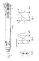
- a cutting torch generally designated 1
- the upper connection part or head 2 of which is cut in the longitudinal direction in the position of use.
- an opto-double diode 4 is accommodated in the upper connection or head part 2, which is preceded by an imaging lens 5.
- the lens 5 serves to image the area which lies in front of or below an opening (not shown) of a nozzle 6 on the opto-double diode.
- the area of interest is the flame emerging from the nozzle 6 during operation of the cutting torch or the part to be machined (cut) of the workpiece not shown below.
- the monolithic opto-double diode consists of a first diode 7 and a second diode 8, which have a common cathode connection 9 (a cathode).
- Anode connections are labeled 10 and 11.
- FIG. 3 shows the relative spectral sensitivity of the first diode with the line 12 and the relative spectral sensitivity of the second diode in FIG. 2 with the line 13 as a function of the wavelength of the light which strikes the two diodes. It can be seen that the first diode line 12 has a maximum near the wavelength 600 nm, while the second line 13 second diode has a maximum near 900 nm.
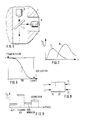
- a sensor arrangement according to FIG. 5 can be accommodated in the connection or head part 2 of the cutting torch, but with a larger space requirement.
- This sensor arrangement essentially consists of a partially transparent mirror 14, in the transmission beam path of which there is a first opto-diode 15, while in the reflection beam path of which a second opto-diode 16 is arranged.
- the transmission-reflection characteristic of the partially transparent mirror is given in FIG. 6.
- the "50% edge" at which the same amount of light is transmitted through the mirror and is reflected, is 700 nm. With longer-wave light, more is detected, below which more light is transmitted through the mirror.
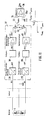
- the evaluation of the output variables of the two sensors or opto-diodes or the opto-double diode can therefore be carried out in basically the same way with the evaluation device 20 shown generally in FIG. 8.
- control commands that are generated to ignite the preheating flame, to run the preheating process and to initiate cutting by supplying cutting oxygen in a conventional control device of a flame cutting machine are fed to the evaluation device via its control input 21.
- a selection of the current evaluation range for the respective operating phase can then be made in the evaluation device by means of discriminators (not shown in FIG. 8 but to be discussed further below). This enables a clear statement of the quotient of the currents i 1 and i 2.
- FIG. 9 The various operating states of the flame cutting machine or the respective cutting torch are indicated in the ordinate axis: off, burning the flame, preheating the workpiece, cutting while supplying cutting oxygen.
- These include evaluation areas 22, 23, 24, 25, in the inner hatched part of which the quotient i2 to i1 is in a desired range and signals the proper functioning of the cutting torch in the respective operating phase.
- An output 26 of the evaluation device accordingly outputs control and monitoring signals which indicate whether the preheating flame is actually burning, whether the ignition temperature has been reached and whether the Cutting torch cuts.
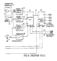
- each of the two currents ID1 and ID2 which correspond to the currents i 1 and i 2 in the preceding figures and which are generated, for example, by the opto-double diode 4, in a part 27, which is delimited by broken lines, fed to the circuit arrangement.
- Each of the two currents is converted in a current-voltage converter 28 or 29 into a proportional voltage, which is amplified in each branch with a logic amplifier 30 or 31.
- the voltages amplified in accordance with the characteristics of the logic amplifiers are subtracted from one another in a subsequent subtractor 32.
- the output voltage of the subtractor is thus approximately the quotient of the input currents ID1 and ID2 and is therefore a measure of the light wavelength received by the opto-double diode.
- Part 27 of FIG. 10 thus corresponds in effect to the quotient image.
- the output variable of the quotient generator or the output voltage of the subtractor 32 is fed into an input 33 of a comparator 34, the second input 35 of which is supplied with a reference voltage.
- the comparator distinguishes whether the voltage corresponding to the light wavelength at the input 33 is above or below the reference voltage by a predetermined value and accordingly forms a control or monitoring signal at its output 36.
- the evaluation device here therefore consists only of a comparator for emitting a control - or monitoring signal.
- the current-voltage converters 28, 29 are each followed by a smoothing low-pass filter 38 or 39, the output voltage of which passes through a simple voltage follower 40 in one branch and an inverting voltage follower 40 in the other branch.
- Resistors 42 and 43 then form a difference between the output voltages of the voltage followers, which as a result represents an approximate quotient formation of the current quantities ID1 and ID2 of the opto-double diode 4.
- This signal representing the quotient runs into the input 33 of the comparator 34.
- the second input 35a of the comparator is grounded here.
- the limit wavelength at which the comparator switches the output variable is determined here by the ratio of the resistors 42 to 43.
- Voltage followers 40 and 41 in FIG. 12 are not only connected to one another via a respective resistor, but rather via a more complex resistor arrangement.
- Potentiometers 47-52 whereby a wiper of each of the potentiometers is led to an input of one of the comparators 53-58.
- the other input of each comparator is here at zero potential.
- a limit wavelength at which a signal change of the output signal of the respective comparator occurs can thus be set on each comparator, as explained in connection with the resistors 42, 43 in FIG. 11.
- Two comparators each, eg 53, 54; 55, 56; 57, 58; are connected together on the output side to form a window comparator 44 or 45 or 46.
- the outputs of the Both comparators, which form a window comparator are linked by a logic element, which can be designed in particular as an AND gate.
- the outputs of the comparators 43, 44 are connected via the logic element 59, the outputs of the comparators 55, 56 via the logic element 60 and the outputs of the comparators 57, 58 via the logic element 61
- Comparators e.g. 53
- a window comparator is assigned to the upper limit of an evaluation range, which is set by the potentiometer 47, and a comparator 54 of the lower limit of the evaluation range, adjustable by the potentiometer 48, thus form both comparators 53, 54 in connection with the Logic element 59 the window comparator 44, which forms a window with an upper and a lower limit, within which an output signal of the logic element assumes a first value and outside the limits of which the output signal adjusts itself to a second value.
- the window comparators 44, 45, 46 each generate output signals for the “flame on” or “hole piercing” or “cutting” state.
- Each of these states or phases corresponds to an evaluation range with the limits that can be set using the potentiometer.
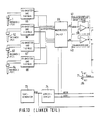
- not only one cutting torch 1 is monitored and controlled, but rather a plurality thereof, including cutting torches 62, 63, 64.
- Each of the cutting torches is equipped with two sensors with different spectral sensitivity, in particular an opto-double diode.
- the output signals of the opto-double diodes namely their currents are in turn, as described in particular in connection with FIG. 11, converted into proportional voltages in a current-voltage converter and smoothed in a low-pass filter.
- the corresponding units of the current-voltage converter and the low-pass filter are designated 65-68 in FIG.
- the output signals from these units 65 - 68 are not processed in parallel, but in a multiplexed manner.
- the output currents of an opto-double diode or two diodes of a pair act on a voltage follower 40 and an inverting voltage follower 41 via a first multiplexer 69, as described in connection with the second embodiment according to FIG. 11 with reference to a cutting torch or a sensor arrangement .
- the evaluation of the output signals of the voltage followers 40 and 41 is then in three window comparators 44, 45, 46, as was explained in detail in connection with the third embodiment in FIG. 12.
- a limit value check is carried out with a comparator 70, one input of which is supplied with the inverted voltage from the inverting voltage follower 41 and the second, not designated input of which can be set to a minimum voltage via a potentiometer 71, at which a switchover takes place.
- the set resistance value of the potentiometer is thus used for limit value control.
- the outputs of the window comparators 44, 45, 46 to be switched over for emitting monitoring and control signals of the cutting torch being monitored in accordance with the setting of the first multiplexer 69 are fed into a second multiplexer 72.
- the switching of the multiplexers takes place synchronously controlled by a clock generator 73 and an address counter 74 and, as far as the second multiplexer 72 is concerned, via an addressable register 75.
- the addressable register is connected to the second multiplexer 72 via a line 76.
- the further control of the second multiplexer 72 is carried out depending on a range selection on lines 77 and 78 and on the output signal of the comparator 70 on a line 79.
- the evaluation areas are ultimately activated here by the second multiplexer 72.
- the assignment of the selected evaluation area to one of the cutting torches 1, 62-64 then takes place via the addressable register 75 In this way, several cutting torches or cutting points can be reliably monitored and controlled with relatively little effort.
Abstract
Description
Die Erfindung betrifft eine Einrichtung zur optisch-elektronischen Steuerung einer Brennschneidmaschine nach dem Oberbegriff des Anspruchs 1.The invention relates to a device for the optical-electronic control of a cutting machine according to the preamble of
Es ist bereits bekannt, einen Gasschneidevorgang über ein auf die Schneidflamme gerichtetes fotoelektrisches Element kontinuierlich zu steuern, indem eine Änderung der Helligkeit eines Teils des Gasschneidens mit oxydierender Reaktion mit Hilfe des fotoelektrischen Elements erfaßt wird (DE-AS 22 03 194). Damit soll der Gasschneidevorgang durch automatische Steuerung der Schneidgeschwindigkeit sowie durch Anhalten der Schneidvorrichtung, z.B. bei einem Fehlzünden, gesteuert werden. Im einzelnen ist das fotoelektrische Element am oberen Ende eines Brenners angebracht und auf den hell leuchtenden Teil der Flamme über eine zentrale Bohrung für den Schneidsauerstoff in dem Brenner und über einen in der Schneiddüse des Brenners vorgesehenen Kanal ausgerichtet. Die Schneidgeschwindigkeit wird durch Erfassen der Änderung der Ausgangsspannung des fotoelektrischen Elements innerhalb eines vorbestimmten Bereiches kontinuierlich gesteuert. Mit diesem fotoelektrischen Element wird jedoch nur ein Kriterium, nämlich die Änderung der Helligkeit des Teils des Gasschneidens mit oxydierender Reaktion erfaßt, um den Gasschneidevorgang anzuhalten, wenn eine Fehlzündung auftritt, und um die Schneidgeschwindigkeit zu steuern.It is already known to continuously control a gas cutting process via a photoelectric element directed onto the cutting flame by detecting a change in the brightness of a part of the gas cutting with an oxidizing reaction with the aid of the photoelectric element (DE-AS 22 03 194). The gas cutting process is thus intended to be carried out by automatically controlling the cutting speed and by stopping the cutting device, e.g. in the event of a misfire. In particular, the photoelectric element is attached to the upper end of a burner and is aligned with the bright part of the flame via a central bore for the cutting oxygen in the burner and via a channel provided in the cutting nozzle of the burner. The cutting speed is continuously controlled by detecting the change in the output voltage of the photoelectric element within a predetermined range. However, this photoelectric element detects only one criterion, namely the change in the brightness of the part of the gas cutting with an oxidizing reaction, to stop the gas cutting operation when a misfire occurs and to control the cutting speed.
Um eine Leistungssteigerung des Brennschneidens herbeizuführen und Material zu sparen, ist bereits vorgeschlagen worden, die Temperatur der Flamme, die Zündtemperatur des zu schneidenden Metalls und die Temperatur der Stirnschnittfläche beim Schneiden getrennt zu erfassen und auszuwerten. Dabei wird ein Signal entsprechend der Flammentemperatur zur Steuerung der Gaszufuhr ausgewertet, ein Signal der Zündtemperatur des Metalls zur Steuerung des Schneidsauerstoffes und für die Bewegung des Strahls ausgewertet und das Signal der Temperatur der Stirnschnittfläche für die Befehlsausgabe zur Unterbrechung des Schneidprozesses ausgewertet.In order to bring about an increase in the power of flame cutting and to save material, it has already been proposed to separately record and evaluate the temperature of the flame, the ignition temperature of the metal to be cut and the temperature of the face cut surface during cutting. A signal corresponding to the flame temperature is used Control of the gas supply evaluated, a signal of the ignition temperature of the metal for controlling the cutting oxygen and for the movement of the jet evaluated and the signal of the temperature of the end face for the command output to interrupt the cutting process evaluated.
Hierzu besteht bei der vorgeschlagenen optisch-elektronischen Steuerung ein in dem Brenner mit dem Kanal des Schneidsauerstoffs untergebrachter Fotogeber aus drei einzelnen Fotoelementen, die unabhängig voneinander mit der Auswerteeinrichtung verbunden sind. Die Fotoelemente weisen unterschiedliche spektrale Empfindlichkeiten auf. So ist ein erstes Fotoelement mit einem Steuerungssystem für die Zufuhr des Gases und für Koordinatenantriebe verbunden und seine optische Charakteristik (Empfindlichkeit) soll der Temperatur der Flamme entsprechen. Ein zweites Fotoelement ist mit einem Steuerungssystem für die Zufuhr des Schneidsauerstoffes und für die Koordinatenantriebe verbunden; seine optische Charakteristik soll der Zündtemperatur des Metalls entsprechend. Ein drittes Fotoelement ist ebenfalls mit dem Steuerungssystem für den Schneidsauerstoff und für die Koordinatenantriebe verbunden, seine optische Charakteristik soll jedoch der Temperatur der Stirnschneidfläche angepaßt sein. Die Anpassung der optischen Charakteristiken der drei Fotoelemente hatte nur den Zweck, deren Empfindlichkeit im Hinblick auf das von dem jeweiligen Fotoelement erfaßte optische Phänomen zu maximieren. Ausgewertet wurden die Ausgangssignale der Fotoelemente lediglich getrennt und hinsichtlich ihrer Amplitude, d.h. der Helligkeit der Flamme oder des Werkstücks in dem spektralen Empfindlichkeitsbereich des jeweiligen Fotoelements. Die Auswertung der Amplituden der Ausgangssignale ergibt jedoch bei dem Einbau der Fotoelemente in den Schneidbrenner keine eindeutige Aussage über die Existenz der beispielsweise überwachten Flamme, des Erreichens der Zündtemperatur oder des Schneidens des Brenners, weil die Amplituden der Ausgangssignale der Fotoelemente starken Störeinflüssen unterliegen. So treten störende Änderungen des Amplitudenpegels bei einem Düsenwechsel auf, sowie Änderungen der Höhe des Brenners über dem Werkstücks und bei Variationen der Schneidgeschwindigkeit.For this purpose, in the case of the proposed optical-electronic control, a photo transmitter, which is accommodated in the burner with the channel of the cutting oxygen, consists of three individual photo elements which are connected to the evaluation device independently of one another. The photo elements have different spectral sensitivities. A first photo element is connected to a control system for the supply of gas and for coordinate drives and its optical characteristic (sensitivity) should correspond to the temperature of the flame. A second photo element is connected to a control system for the supply of the cutting oxygen and for the coordinate drives; its optical characteristic should correspond to the ignition temperature of the metal. A third photo element is also connected to the control system for the cutting oxygen and for the coordinate drives, but its optical characteristics should be adapted to the temperature of the face cutting surface. The purpose of adjusting the optical characteristics of the three photo elements was only to maximize their sensitivity to the optical phenomenon detected by the respective photo element. The output signals of the photo elements were only evaluated separately and with regard to their amplitude, ie the brightness of the flame or the workpiece, in the spectral sensitivity range of the respective photo element. The evaluation of the amplitudes of the output signals, however, does not provide any clear information about the existence of the monitored flame, the reaching of the ignition temperature or the cutting of the torch when the photo elements are installed in the cutting torch, because the amplitudes of the output signals of the Photo elements are subject to strong interference. Disruptive changes in the amplitude level occur when changing the nozzle, changes in the height of the torch above the workpiece and variations in the cutting speed.
Der Erfindung liegt daher die Aufgabe zugrunde, eine Einrichtung der eingangs genannten Gattung so weiterzuentwickeln, daß die Ausgangssignale der fotoelektrischen Sensoren eindeutige Kriterien zur Bildung von Steuer- und Überwachungssignalen selbsttätig erzeugen, ohne verfälschenden Störeinflüssen ausgesetzt zu sein. Die kompakte Anordnung der fotoelektrischen Sensoren in dem Schneidbrenner sollte dabei nach Möglichkeit erhalten bleiben.The invention is therefore based on the object of further developing a device of the type mentioned at the outset such that the output signals of the photoelectric sensors automatically generate clear criteria for the formation of control and monitoring signals without being exposed to falsifying interference. The compact arrangement of the photoelectric sensors in the cutting torch should be retained if possible.
Diese Aufgabe wird durch die Ausbildung der Einrichtung zur optisch-elektronischen Steuerung mit den in dem kennzeichnenden Teil des Anspruchs 1 angegebenen Mitteln gelöst.This object is achieved by the design of the device for optical-electronic control with the means specified in the characterizing part of
Wesentlich ist hierbei, daß nicht mehr jedem fotoelektrisch zu überwachenden Phänomen des Brennschneidens eine von mehreren fotoelektrischen Sensoren unterschiedlicher spektraler Empfindlichkeit, deren Ausgangsgrößen getrennt ausgewertet werden, zugeordnet ist, sondern daß alle interessierenden Vorgänge mit vorzugsweise einem Paar fotoelektrischer Sensoren unterschiedlicher spektraler Empfindlichkeit erfaßt werden, deren Ausgangssignale in elektronischen Mitteln zur Quotientenbildung in Relation zueinander gesetzt werden, so daß die Ausgangssignale nicht mehr ein Maß für die Helligkeit des von den fotoelektrischen Sensoren erfaßten Bereichs sind, sondern deren (Farb-)Temperatur entsprechen, vorzugsweise proportional sind. Demzufolge haben Einflüsse, welche die Amplituden der von den fotoelektrischen Sensoren abgegebenen Ausgangssignale gleichmäßig beeinflussen, keine störende Auswirkung auf die Ausgangssignale und deren Auswertung.It is important here that each photoelectrically monitored phenomenon of flame cutting is no longer assigned one of several photoelectric sensors with different spectral sensitivity, the output values of which are evaluated separately, but that all processes of interest are preferably recorded with a pair of photoelectric sensors with different spectral sensitivity, the Output signals are set in relation to one another in electronic means for forming the quotient, so that the output signals are no longer a measure of the brightness of the area detected by the photoelectric sensors, but rather correspond to their (color) temperature, preferably are proportional. As a result, influences which influence the amplitudes of the output signals emitted by the photoelectric sensors uniformly have no disruptive effect on the output signals and their evaluation.
Um eindeutige Steuer- und Überwachungssignale für die verschiedenen Phasen oder Zustände zu erhalten, sind in der Auswerteeinrichtung, die mit dem Quotient der Ausgangsgrößen der Sensoren beaufschlagt wird, nach Anspruch 2 Diskriminatoren für verschiedene Auswertebereiche dieses Quotienten vorgesehen, von denen jeweils ein Auswertebereich in Abhängigkeit von dem Auftreten eines externen Steuerkommandos aktivierbar ist. Es ist also jeweils ein Auswertebereich einer Phase des Brennschneidens zugeordnet, damit aus der bei dieser Phase durch die Sensoren und die Quotientenbildung ermittelte Wellenlänge des empfangenen Lichts eine eindeutige, auf diese Phase bezogene Aussage gewonnen werden kann, die zur weiteren Steuerung des Brennschneidens genutzt wird. Im einzelnen sind diese Phasen bzw. Auswertebereiche das Brennen der (Vorwärm-)Flamme, der Verlauf des Vorwärmens desIn order to obtain unambiguous control and monitoring signals for the different phases or states, discriminators for different evaluation areas of this quotient are provided in the evaluation device, which is supplied with the quotient of the output variables of the sensors, of which one evaluation area depending on the occurrence of an external control command can be activated. An evaluation area is assigned to each phase of the flame cutting, so that a clear statement relating to this phase can be obtained from the wavelength of the received light determined by the sensors and the formation of the quotient, which is used for further control of the flame cutting. In detail, these phases or evaluation areas are the burning of the (preheating) flame, the course of the preheating of the
Werkstücks sowie der eigentliche Schneidvorgang unter Schneidsauerstoffzufuhr. Je nach dem beabsichtigten Anwendungsbereich der Einrichtung können diese und gegebenenfalls weitere Phasen bestimmt werden und durch Einsatz eines Diskriminators in der Auswerteeinrichtung realisiert werden.Workpiece and the actual cutting process with cutting oxygen supply. Depending on the intended field of application of the device, these and possibly other phases can be determined and implemented by using a discriminator in the evaluation device.
Als Geber der externen Steuerkommandos zum Aktivieren der Diskriminatoren bzw. Auswertebereiche in der Auswerteeinrichtung sind nach Anspruch 3 solche Geber vorgesehen, die Steuerkommandos zum Zünden der Flamme, zum Vorwärmen des Werkstücks und zum Schneiden unter Schneidsauerstoffzufuhr abgeben. Solche Geber gehören in der Regel zur Grundausstattung der Steuerung einer Brennschneidmaschine, so daß sie den Aufwand im Zusammenhang mit der vorliegenden Erfindung nicht erhöhen; vielmehr haben diese Geber hier nur eine neue, zusätzliche Funktion.As transmitters of the external control commands for activating the discriminators or evaluation areas in the evaluation device, such transmitters are provided according to
Zur Unterbringung der fotoelektrischen Sensoren in dem Kopf eines Brenners besonders geeignet, da sehr kompakt, ist nach Anspruch 4 eine Opto-Doppeldiode auf einem gemeinsamen Sub strat. Die Dioden der Opto-Doppeldiode weisen dabei unterschiedliche Empfindlichkeitsmaxima in Abhängigkeit von der Lichtwellenlänge auf. Eine solche monolitische Doppeldiode ist unter der Bezeichnung PD 153 (Firma Sharp, Japan) bekannt. Sie besteht im wesentlichen aus zwei Dioden unterschiedlicher spektraler Empfindlichkeit mit einer gemeinsamen Kathode. Die beiden Anodenanschlüsse und der gemeinsame Kathodenanschluß sind aus der Doppeldiode herausgeführt. Das Lichtempfindlichkeitsmaximum der einen Diode liegt etwas unterhalb 600 nm, während das Lichtempfindlichkeitsmaximum der anderen Diode bei 900 nm ist. - Die Kombination zweier Sensoren mit der voranstehend angegebenen unterschiedlichen spektralen Empfindlichkeit ergibt einen verhältnismäßig großen auswertbaren Bereich der empfangenen Lichtwellenlänge.Particularly suitable for accommodating the photoelectric sensors in the head of a burner, since it is very compact, is an opto-double diode on a common sub strat. The diodes of the opto-double diode have different sensitivity maxima depending on the light wavelength. Such a monolithic double diode is known under the name PD 153 (Sharp, Japan). It essentially consists of two diodes of different spectral sensitivity with a common cathode. The two anode connections and the common cathode connection are led out of the double diode. The light sensitivity maximum of one diode is slightly below 600 nm, while the light sensitivity maximum of the other diode is 900 nm. - The combination of two sensors with the different spectral sensitivity given above results in a relatively large evaluable range of the received light wavelength.
Bei einer Variante des Paars Sensoren unterschiedlicher spektraler Empfindlichkeit können gleichartigen Opto-Dioden, d.h. solche mit gleicher spektraler Empfindlichkeit verwendet werden, wenn gemäß Anspruch 5 eine der beiden Opto-Dioden in einem Reflexionsstrahlengang und eine andere der beiden Opto-Dioden in Transmissionsstrahlengangs eines teildurchlässigen Spiegels angeordnet sind, der eine spektral unterschiedliche Reflexion und Transmission aufweist. Insbesondere kann der Spiegel für die vorliegende Anwendung vorteilhaft so beschaffen sein, daß er jeweils den gleichen Lichtstromteil durchläßt und reflektiert bei einer Lichtwellenlänge von 700 nm ("50 %-Kante").In a variant of the pair of sensors with different spectral sensitivity, similar opto-diodes, i.e. those with the same spectral sensitivity are used if, according to
In einer wiederum anderen Ausführungsform der beiden Sensoren unterschiedlicher spektraler Empfindlichkeit können diese aus je einer getrennten Opto-Diode unterschiedlicher spektraler Charakteristik bzw. Empfindlichkeit nach Anspruch 6 bestehen.In yet another embodiment of the two sensors of different spectral sensitivity, these can each consist of a separate opto-diode with different spectral characteristics or sensitivity according to
Als solche Opto-Dioden unterschiedlicher spektraler Charakteristik können insbesondere nach Anspruch 7 je eine optische Germaniumdiode und eine Siliziumdiode vorgesehen sein.As such opto-diodes of different spectral characteristics can be optical, in particular according to claim 7 Germanium diode and a silicon diode may be provided.
Wesentlich ist bei allen Ausführungsformen, daß durch die Quotientenbildung der Ausgangsgrößen bzw. Ausgangssignale der beiden Sensoren unterschiedlicher spektraler Empfindlichkeit ein resultierendes Signal von der absoluten Lichtmenge, mit der beide Sensoren beaufschlagt werden, unabhängig ist und nur eine Abhängigkeit von der empfangenen Lichtwellenlänge aufweist.It is essential in all embodiments that, by forming the quotient of the output variables or output signals of the two sensors of different spectral sensitivity, a resultant signal is independent of the absolute amount of light with which both sensors are exposed and has only a dependence on the received light wavelength.
Die elektronischen Mittel zur Quotientenbildung können vereinfachend durch wenigstens einen Subtrahierer nach Anspruch 8 realisiert sein, in welchem der Quotient der Ausgangsgrößen der Sensoren unterschiedlicher spektraler Empfindlichkeit näherungsweise gebildet wird.The electronic means for forming the quotient can be implemented in a simplified manner by at least one subtractor according to
In einer Weiterbildung der letztgenannten Einrichtung kann nach Anspruch 9 jedem der beiden Eingänge des Subtrahierers je ein Logik-Verstärker vorgeschaltet sein, der mit je einer der Ausgangsgrößen der Sensoren unterschiedlicher spektralerIn a further development of the latter device, according to
Empfindlichkeit beaufschlagt wird, um eine genauere Quotientenbildung in Verbindung mit dem Subtrahierer zu erreichen.Sensitivity is applied to achieve a more accurate quotient formation in connection with the subtractor.
Um aus den Ausgangssignalen bzw. Ausgangsgrößen der Sensoren ein definiertes Steuer- oder Überwachungssignal zu bilden, nachdem die Quotienten- oder Differenzbildung erfolgt ist, wird nach Anspruch 10 in der Auswerteeinrichtung wenigstens ein Comparator als Diskriminator vorgesehen. Der Diskriminator gibt je ein definiertes Ausgangssignal in Abhängigkeit davon ab, ob die Sensoren mit Licht über oder unter einer Grenzwellenlänge beaufschlagt werden. Die Grenzwellenlänge wird durch das Referenzsignal, insbesondere eine Referenzspannung bestimmt, mit dem ein Eingang des Comparators beaufschlagt wird.In order to form a defined control or monitoring signal from the output signals or output variables of the sensors after the formation of the quotient or difference, at least one comparator is provided as a discriminator in the evaluation device. The discriminator emits a defined output signal depending on whether the sensors are exposed to light above or below a limit wavelength. The limit wavelength is determined by the reference signal, in particular a reference voltage, with which an input of the comparator is applied.
Um je einen Auswertebereich festzulegen, innerhalb dessen ein überwachter Vorgang bzw. eine Phase des Schneidbrennens im Sollbereich ist, wird nach Anspruch 11 in der auswerteeinrichtung als Diskriminator je ein Fenstercomparator eingesetzt, der zwei Comparatoren umfaßt, von denen je einer auf eine Obergrenze sowie auf eine Untergrenze des aktivierbaren Auswertebereichs bzw. Sollbereichs voreinstellbar ist. Die Ausgänge der Comparatoren sind dabei über ein Logik-Element miteinander verknüpft, um ein Steuer- oder Überwachungssignal bzw. Bereitschaftssignal abzugeben, wenn die Ausgangsgrößen der Comparatoren innerhalb des Sollbereichs liegen. Die Grenzen des Sollbereichs können mit den Referenzsignalen bzw. Referenzspannungen an den Comparatoren eingestellt werden, wobei eine individuelle Einstellung der oberen Grenzen und der unteren Grenze möglich ist.In order to define an evaluation range within which a monitored process or a phase of cutting is in the target range, a window comparator is used in the evaluation device as a discriminator, which comprises two comparators, one of which each has an upper limit and one The lower limit of the evaluation range or target range that can be activated can be preset. The outputs of the comparators are linked to one another via a logic element in order to emit a control or monitoring signal or readiness signal if the output variables of the comparators are within the target range. The limits of the target range can be set with the reference signals or reference voltages on the comparators, whereby the upper limits and the lower limit can be set individually.
Zur Überwachung mehrerer Schneidbrenner einer Brennschneidmaschine sind die im einzelnen in dem Anspruch 12 angegebenen Merkmale vorgesehen. Wesentlich ist hierbei, daß nicht jedem Paar fotoelektrischer Sensoren unterschiedlicher spektraler Empfindlichkeit eine vollständige Auswerteeinrichtung mit Diskriminatoren bzw. Fenstercomparatoren für die einzelnen Auswertebereiche zugeordnet ist, sondern daß nur ein Satz Diskriminatoren bzw. Fenstercomparatoren im Zeitmultiplexverfahren mehrfach, nämlich für sämtliche Paare Sensoren genutzt werden. Zu der entsprechenden Einrichtung gehören nicht nur Multiplexer am Eingang und am Ausgang der Auswerteeinrichtung, sondern ein adressierbares Register, welches die in der Auswerteeinrichtung gebildeten Steuer- und Überwachungssignale den einzelnen Schneidbrennern in einer vorprogrammierten Folge zuordnet.The features specified in claim 12 are provided for monitoring several cutting torches of a flame cutting machine. It is important here that a complete evaluation device with discriminators or window comparators for the individual evaluation areas is not assigned to each pair of photoelectric sensors with different spectral sensitivity, but that only one set of discriminators or window comparators is used multiple times, namely for all pairs of sensors. The corresponding device not only includes multiplexers at the input and output of the evaluation device, but also an addressable register which assigns the control and monitoring signals formed in the evaluation device to the individual cutting torches in a preprogrammed sequence.
Die Erfindung wird im folgenden anhand einer Zeichnung mit 13 Figuren erläutert. Es zeigen:
- Fig. 1 einen Schneidbrenner, in dem die fotoelektrischen Sensoren untergebracht sind, in einer Seitenansicht, teilweise geschnitten,
- Fig. 2 schematisch die beiden Sensoren unterschiedlicher spektraler Empfindlichkeit als monolitische Opto-Doppeldiode,
- Fig. 3 einen typischen Verlauf der spektralen Empfindlichkeit der beiden Dioden der Opto-Doppeldiode nach Fig. 2 in Abhängigkeit von der Wellenlänge des Lichts,
- Fig. 4 das Verhältnis der Ausgangsgrößen, nämlich der Ausgangsströme der beiden Dioden nach Fig. 2 ebenfalls in Abhängigkeit von der Wellenlänge des Lichts,
- Fig. 5 eine schematische Darstellung der Anordnung der beiden Sensoren mit einem teildurchlässigen Spiegel,
- Fig. 6 die Transmissions-Reflexionskennlinie des teildurchlässigen Spiegels in Abhängigkeit von der Lichtwellenlänge,
- Fig. 7 die Ausgangsgrößen, nämlich Ausgangsströme der beiden Sensoren gemäß Fig. 5,
- Fig. 8 eine Auswerteeinrichtung in Blockdarstellung,
- Fig. 9 die Auswertebereiche in Abhängigkeit von bestimmten Phasen des Schneidvorgangs einschließlich vorbereitungsphasen,
- Fig. 10 - 13 Blockschaltbilder von vier Ausführungsformen der Einrichtung zur optisch-elektronischen Steuerung der Brennschneidmaschine.
- 1 shows a cutting torch, in which the photoelectric sensors are housed, in a side view, partly in section,
- 2 schematically shows the two sensors of different spectral sensitivity as a monolithic opto-double diode,
- 3 shows a typical course of the spectral sensitivity of the two diodes of the opto-double diode according to FIG. 2 as a function of the wavelength of the light,
- 4 shows the ratio of the output variables, namely the output currents of the two diodes according to FIG. 2, also as a function of the wavelength of the light,
- 5 shows a schematic representation of the arrangement of the two sensors with a partially transparent mirror,
- 6 shows the transmission-reflection characteristic of the partially transparent mirror as a function of the light wavelength,
- 7 shows the output variables, namely output currents of the two sensors according to FIG. 5,
- 8 is an evaluation device in block diagram,
- 9 shows the evaluation areas as a function of certain phases of the cutting process, including preparation phases,
- 10 - 13 block diagrams of four embodiments of the device for the optical-electronic control of the flame cutting machine.
In Fig. 1 ist ein allgemein mit 1 bezeichneter Schneidbrenner dargestellt, dessen in Gebrauchslage oberer Anschlußteil oder Kopftel 2 in Längsrichtung geschnitten ist.In Fig. 1, a cutting torch, generally designated 1, is shown, the upper connection part or
In Verlängerung eines Schneidsauerstoffkanals 3 ist in dem oberen Anschluß- oder Kopfteil 2 eine Opto-Doppeldiode 4 untergebracht, der eine abbildende Linse 5 vorgeschaltet ist. Die Linse 5 dient dazu, den Bereich, der vor bzw. unter einer nicht dargestellten Öffnung einer Düse 6 liegt, auf die Opto-Doppeldiode abzubilden. Der interessierende Bereich ist die beim Betrieb des Schneidbrenners aus der Düse 6 austretende Flamme bzw. das zu bearbeitende (schneidende) Teil des darunterliegenden nicht dargestellten Werkstücks.In the extension of a cutting
In Fig. 2 ist dargestellt, daß die monolitische Opto-Doppeldiode aus einer ersten Diode 7 und einer zweiten Diode 8 besteht, die einen gemeinsamen Kathodenanschluß 9 (einer Kathode) aufweisen. Anodenanschlüsse sind mit 10 und 11 bezeichnet.In Fig. 2 it is shown that the monolithic opto-double diode consists of a first diode 7 and a
In Fig. 3 ist die relative spektrale Empfindlichkeit der ersten Diode mit dem Linienzug 12 und die relative spektrale Empfindlichkeit der zweiten Diode in Fig. 2 mit dem Linienzug 13 in Abhängigkeit von der Wellenlänge des Lichts, welche auf die beiden Dioden trifft, wiedergegeben. Es ist ersichtlich, daß die erste Diode - Linienzug 12 - ein Maximum nahe der Wellenlänge 600 nm aufweist, während der zweite Linienzug 13 - zweite Diode - ein Maximum nahe 900 nm hat.FIG. 3 shows the relative spectral sensitivity of the first diode with the line 12 and the relative spectral sensitivity of the second diode in FIG. 2 with the line 13 as a function of the wavelength of the light which strikes the two diodes. It can be seen that the first diode line 12 has a maximum near the
Wenn das Verhältnis der Ausgangsgrößen der zweiten Diode 8 zu der ersten Diode 7 in Fig. 2 gebildet wird, nämlich das Verhältnis deren Kurzschlußströme, so verläuft die Abhängigkeit von der Lichtwellenlänge wie in Fig. 4 dargestellt. Es ist ersichtlich, daß das Verhältnis der Ausgangsströme bzw. Ausgangsgrößen der beiden Dioden in eindeutiger Beziehung zu der Lichtwellenlänge steht.If the ratio of the outputs of the
Statt der Opto-Doppeldiode 4 kann in dem Anschluß- oder Kopfteil 2 des Schneidbrenners eine Sensorenanordnung gemäß Fig. 5 bei allerdings größerem Platzbedarf untergebracht sein. Diese Sensorenanordnung besteht im wesentlichen aus einem teildurchlässigen Spiegel 14, in dessen Transmissionsstrahlengang sich eine erste Opto-Diode 15 befindet, während in dessen Reflexionsstrahlengang eine zweite Opto-Diode 16 angeordnet ist. Die Transmissions-Reflexionskennlinie des teildurchlässigen Spiegels ist in Fig. 6 angegeben. Die "50 %-Kante", bei der gleichviel Licht durch den Spiegel durchgelassen wird und reflektiert wird, liegt bei 700 nm. Bei längerwelligem Licht wird mehr relektiert, darunter wird mehr Licht durch den Spiegel durchgelassen.Instead of the opto-
Hieraus resultiert eine Abhängigkeit der Ausgangsgrößen bzw. Ausgangsströme der beiden Opto-Dioden 15 und 16 gemäß den Linienzügen 17 und 18 in Abhängigkeit von der Lichtwellenlänge wie in Fig. 7 dargestellt. Wenn aus beiden Ausgangsströmen i₁ und i₂ der Opto-Dioden 15 und 16 das Verhältnis gebildet wird, kann sich ein ähnlich definierter Kennlinienverlauf wie in Fig. 4 zu der Opto-Doppeldiode dargestellt einstellen.This results in a dependency of the output quantities or output currents of the two opto-
Die Auswertung der Ausgangsgrößen der beiden Sensoren bzw. Opto-Dioden oder der Opto-Doppeldiode kann daher in grundsätzlich gleicher Weise mit der in Fig. 8 allgemein dargestellten Auswerteeinrichtung 20 erfolgen.The evaluation of the output variables of the two sensors or opto-diodes or the opto-double diode can therefore be carried out in basically the same way with the
Unabhängig davon, ob die Ausgangsströme i₁ und i₂ der getrennten Opto-Dioden 15 und 16 ausgewertet werden sollen oder die Ausgangsströme der Opto-Doppeldiode 4, gelangen diese Ausgangsströme zunächst gemäß Fig. 8 in einen Quotientenbilder 19, in welchem das Verhältnis der beiden Ströme zumindest näherungsweise gebildet wird. Dieser Quotient ist entsprechend Fig. 4 ein Maß für die empfangene Lichtwellenlänge. Um aus diesem Quotienten eindeutige Steuer- oder Überwachungssignale zu bilden, wird in der Auswerteeinrichtung 20 unterschieden, um welche Phase, einschließlich Vorbereitungsphase des Schneidbrennens es sich bei der aktuellen Lichtwellenlängenmessung handelt. Hierzu werden Steuerkommandos, die zum Zünden der Vorwärmflamme, zum Ablauf des Vorwärmprozesses und zum Einleiten des Schneidens durch Zufuhr von Schneidsauerstoff in einer üblichen Steuerungseinrichtung einer Brennschneidmaschine erzeugt werden, der Auswerteeinrichtung über deren Steuereingang 21 zugeführt. Es kann dann in der Auswerteeinrichtung durch in Fig. 8 nicht dargestellte, jedoch weiter unten zu besprechende Diskriminatoren eine Auswahl des für die jeweilige Betriebsphase aktuellen Auswertebereichs getroffen werden. Damit wird eine eindeutige Aussage des Quotienten der Ströme i₁ und i₂ ermöglicht.Regardless of whether the output currents i 1 and
In Fig. 9 ist dieser Zusammenhang schaubildlich dargestellt. In der Ordinatenachse sind die verschiedenen Betriebszustände der Brennschneidmaschine bzw. des jeweiligen Schneidbrenners angegeben: Aus, Brennen der Flamme, Vorwärmen des Werkstücks, Schneiden unter Schneidsauerstoffzufuhr. Hierzu gehören Auswertebereiche 22, 23, 24, 25, in derem inneren schraffiertem Teil sich der Quotient i₂ zu i₁ in einem Sollbereich befindet und die ordnungsgemäße Funktion des Schneidbrenners in der jeweiligen Betriebsphase signalisiert. Ein Ausgang 26 der Auswerteeinrichtung gibt demgemäß Steuer- und Überwachungssignale ab, die angeben, ob die Vorwärmflamme tatsächlich brennt, ob die Zündtemperatur erreicht ist und ob der Schneidbrenner schneidet.This relationship is shown graphically in FIG. 9. The various operating states of the flame cutting machine or the respective cutting torch are indicated in the ordinate axis: off, burning the flame, preheating the workpiece, cutting while supplying cutting oxygen. These include evaluation areas 22, 23, 24, 25, in the inner hatched part of which the quotient i₂ to i₁ is in a desired range and signals the proper functioning of the cutting torch in the respective operating phase. An
In der ersten Ausführungsform der elektronischen Mittel zur Quotientenbildung und der Auswerteeinrichtung nach Fig. 10 wird jeder der beiden Ströme ID1 bzw. ID2, welche den Strömen i₁ und i₂ in den vorangehenden Figuren entsprechen und die beispielsweise von der Opto-Doppeldiode 4 erzeugt werden, in einen Teil 27, der durch unterbrochene Linien begrenzt ist, der Schaltungsanordnung eingespeist. Jeder der beiden Ströme wird in einem Stromspannungsumsetzer 28 bzw. 29 in eine proportionale Spannung umgesetzt, die in je einem Zweig mit einem logischen Verstärker 30 bzw. 31 verstärkt wird. Die entsprechend den Kennlinien der logischen Verstärker verstärkten Spannungen werden in einem nachfolgenden Subtrahierer 32 voneinander subtrahiert. Die Ausgangsspannung des Subtrahierers ist somit angenähert der Quotient der Eingangsströme ID1 und ID2 und ist damit ein Maß für die von der Opto-Doppeldiode empfangenen Lichtwellenlänge. Der Teil 27 der Fig. 10 entspricht also wirkungsmäßig dem Quotientenbilder.In the first embodiment of the electronic means for quotient formation and the evaluation device according to FIG. 10, each of the two currents ID1 and ID2, which correspond to the currents i 1 and
Die Ausgangsgröße des Quotientenbilders bzw. die Ausgangsspannung des Subtrahierers 32 wird in einen Eingang 33 eines Comparators 34 eingespeist, dessen zweiter Eingang 35 mit einer Referenzspannung beaufschlagt wird. Der Comparator unterscheidet, ob die der Lichtwellenlänge entsprechende Spannung an dem Eingang 33 um einen vorgegebenen Wert über oder unter der Referenzspannung liegt und bildet demgemäß ein Steuer- oder Überwachungssignal an seinem Ausgang 36. Die Auswerteeinrichtung besteht hier also nur aus einem Comparator zur Abgabe eines Steuer- oder Überwachungssignals.The output variable of the quotient generator or the output voltage of the
Die zweite Ausführungsform gemäß Fig. 11, in der gleiche Komponenten wie in Fig. 10 mit übereinstimmenden Bezugszeichen versehen sind, unterscheidet sich von der ersten Auführungsform nur durch Einzelheiten der Quotientenbildung in einem Teil 37. Auf die Stromspannungsumsetzer 28, 29 folgt hier jeweils ein glättender Tiefpaß 38 bzw. 39, dessen Ausgangsspannung in dem einen Zweig einen einfachen Spannungsfolger 40 durchläuft und in dem anderen Zweig einen invertierenden Spannungsfolger 40. Durch Zusammenschalten der Ausgänge der Spannungsfolger 40 und 41 über Widerstände 42 und 43 erfolgt dann eine Differenzbildung der Ausgangsspannungen der Spannungsfolger, die im Ergebnis eine angenäherte Quotientenbildung der Stromgrößen ID1 und ID2 der Opto-Doppeldiode 4 darstellt. Dieses den Quotienten repräsentierende Signal läuft in den Eingang 33 des Comparators 34 ein. Der zweite Eingang 35a des Comparators ist hier geerdet. Die Grenzwellenlänge, bei der der Comparator die Ausgangsgröße umschaltet, wird hier durch das Verhältnis der Widerstände 42 zu 43 bestimmt.The second embodiment according to FIG. 11, in which the same components as in FIG. 10 are provided with the same reference numerals, differs from the first embodiment only in the details of forming the quotient in one Part 37. The current-
In der dritten Ausführungsform der Einrichtung nach Fig. 12 liegen Übereinstimmungen zu der zweiten Ausführungsform gemäß Fig. 11 im wesentlichen bis einschließlich des Teils 37a auf, welcher dem Teil 37 in Fig. 11 entspricht. Die Ausgänge derIn the third embodiment of the device according to FIG. 12, there are similarities to the second embodiment according to FIG. 11 essentially up to and including part 37a, which corresponds to part 37 in FIG. 11. The outputs of the
Spannungsfolger 40 und 41 sind in Fig. 12 jedoch nicht nur über je einen Widerstand miteinander verbunden, sondern über eine komplexere Widerstandsanordnung. Eine Zusammenschaltung zweier Widerstände, wie in Fig. 11 der Widerstände 42, 43, liegt in der dritten Ausführungsform in je einem der
Potentiometer 47 - 52 vor, wobei ein Schleifer jedes der Potentiometer zu je einem Eingang eines der Comparatoren 53 - 58 geführt ist. Der jeweils andere Eingang jedes Comparators ist hier auf Nullpotential. An jedem Comparator kann somit, wie im Zusammenhang mit den Widerständen 42, 43 in Fig. 11 erläutert, eine Grenzwellenlänge eingestellt werden, bei der ein Signalwechsel des Ausgangssignals des jeweiligen Comparators eintritt. Jeweils zwei Comparatoren, z.B. 53, 54; 55, 56; 57, 58; sind zu einem Fenstercomparator 44 bzw. 45 bzw. 46 ausgangsseitig zusammengeschaltet. Die Ausgänge der beiden Comparatoren, die einen Fenstercomparator bilden, sind durch ein Logik-Element verknüpft, welches insbesondere als UND-Glied ausgebildet sein kann. Im einzelnen sind die Ausgänge der Comparatoren 43, 44 über das Logik-Element 59 verbunden, die Ausgänge der Comparatoren 55, 56 über das Logik-Element 60 und die Ausgänge der Comparatoren 57, 58 über das Logik-Element 61. Indem jeweils einer der Comparatoren , z.B. 53, eines Fenstercomparators der oberen Grenze eines Auswertebereichs zugeordnet ist, welche durch das Potentiometer 47 eingestellt wird, und ein Comparator 54 der unteren Grenze des Auswertebereichs, einstellbar durch das Potentiometer 48, bilden so beide Comparatoren 53, 54 in Verbindung mit dem Logik-Element 59 den Fenstercomparator 44, der ein Fenster mit einer oberen und einer unteren Grenze bildet, innerhalb deren ein Ausgangssignal des Logik-Elements einen ersten Wert annimmt und außerhalb deren Grenzen das Ausgangssignal sich auf einen zweiten Wert einstellt. In dieser Weise werden durch die Fenstercomparatoren 44, 45, 46 Ausgangssignale jeweils für den Zustand "Flamme an" bzw. "Lochstechen" bzw. "Schneiden" gebildet. Dabei entspricht jeder dieser Zustände oder Phasen einem Auswertebereich mit den durch die Potentiometer einstellbaren Grenzen.Potentiometers 47-52, whereby a wiper of each of the potentiometers is led to an input of one of the comparators 53-58. The other input of each comparator is here at zero potential. A limit wavelength at which a signal change of the output signal of the respective comparator occurs can thus be set on each comparator, as explained in connection with the
In der Ausführungsform gemäß Fig. 13 wird nicht nur ein Schneidbrenner 1 überwacht und gesteuert, sondern deren mehrere, einschließlich der Schneidbrenner 62, 63, 64. Jeder der Schneidbrenner ist dabei mit zwei Sensoren unterschiedlicher spektraler Empfindlichkeit, insbesondere einer Opto-Doppeldiode ausgestattet. Die Ausgangssigna!e der Opto-Doppeldioden, nämlich deren Ströme werden wiederum, wie insbesondere in Verbindung mit Fig. 11 beschrieben, in einem Stromspannungsumsetzer in proportionale Spannungen umgesetzt und in einem Tiefpaß geglättet. Die entsprechenden Einheiten des Stromspannungsumsetzers und des Tiefpasses sind in Fig. 13 mit 65 - 68 bezeichnet. Die Ausgangssignale dieser Einheiten 65 - 68 werden nicht parallel, sondern im Multiplexverfahren zeitlich gestaffelt weiterverarbeitet. Hierzu beaufschlagen jeweils die Ausgangsströme einer Opto-Doppeldiode bzw. zweier Dioden eines Paars über einen ersten Multiplexer 69 einen Spannungsfolger 40 sowie einen invertierenden Spannungsfolger 41, wie im Zusammenhang mit der zweiten Ausführungsform nach Fig. 11 in Bezug auf einen Schneidbrenner bzw. eine Sensorenanordnung beschrieben. Die Auswertung der Ausgangssignale der Spannungsfolger 40 und 41 ist dann in drei Fenstercomparatoren 44, 45, 46, wie im einzelnen in Verbindung mit der dritten Ausführungsform in Fig. 12 erläutert wurde. Zusätzlich erfolgt eine Grenzwertkontrolle mit einem Comparator 70, dessen einer Eingang mit der invertierten Spannung aus dem invertierenden Spannungsfolger 41 beaufschlagt wird und dessen zweiter, nicht bezeichneter Eingang über ein Potentiometer 71 auf eine minimale Spannung einstellbar ist, bei der eine Umschaltung erfolgt. Der eingestellte Widerstandswert des Potentiometers wird somit zur Grenzwertkontrolle hera gezogen. Die umzuschaltenden Ausgänge der Fenstercomparatoren 44, 45, 46 zur Abgabe von Überwachungs- und Steuersignalen des jeweils überwachten Schneidbrenners gemäß der Einstellung des ersten Multiplexers 69 werden in einen zweiten Multiplexer 72 eingespeist. Die Umschaltung der Multiplexer erfolgt synchron gesteuert durch einen Taktgenerator 73 und einen Adresszähler 74 sowie, was den zweiten Multiplexer 72 betrifft, über ein adressierbares Register 75. Hierzu steht das adressierbare Register mit dem zweiten Multiplexer 72 über eine Leitung 76 in Verbindung. Die weitere Steuerung des zweiten Multiplexers 72 wird in Abhängigkeit von einer Bereichsauswahl auf Leitungen 77 und 78 sowie von dem Ausgangssignal des Comparators 70 auf einer Leitung 79 durchgeführt. Die Aktivierung der Auswertebereiche geschieht hier also letztlich durch den zweiten Multiplexer 72. Die Zuordnung des ausgewählten Auswertebereichs zu einem der Schneidbrenner 1, 62 - 64 geht dann über das adressierbare Register 75. In dieser Weise können mehrere Schneidbrenner bzw. Schneidstellen mit verhältnismäßig geringem Aufwand zuverlässig überwacht und gesteuert werden.In the embodiment according to FIG. 13, not only one
Claims (13)
dadurch gekennzeichnet,
daß elektronische Mittel (27) zur Quotientenbildung vorgesehen sind, die mit Ausgängen wenigstens zweier der Sensoren (4; 7, 8) unterschiedlicher spektraler Empfindlichkeit derart in Verbindung stehen, daß der Quotient der Ausgangsgrößen der Sensoren gebildet wird, und daß die Mittel zur Quotientenbildung ausgangsseitig mit der Auswerteeinrichtung (20) in Verbindung stehen.1.Device for the optical-electronic control of a flame cutting machine, with photoelectric sensors of different spectral sensitivity, which are arranged in particular in a cutting torch and are operationally directed towards a flame and a workpiece to be cut and which are connected on the output side to an evaluation device, in particular for control signals for the feed of the cutting torch towards the workpiece,
characterized,
that electronic means (27) for quotient formation are provided which are connected to outputs of at least two of the sensors (4; 7, 8) of different spectral sensitivity in such a way that the quotient of the output quantities of the sensors is formed, and that the means for quotient formation are on the output side are connected to the evaluation device (20).
dadurch gekennzeichnet,
daß in der Auswerteeinrichtung Diskriminatoren (Fenstercomparatoren 53 - 58) für verschiedene Auswertebereiche des Quotienten der Ausgangsgrößen der Sensoren vorgesehen sind, von denen jeweils ein Auswertebereich in Abhängigkeit von dem Auftreten eines externen Steuerkommandos aktivierbar ist.2. Device according to claim 1,
characterized,
that discriminators (window comparators 53-58) are provided in the evaluation device for different evaluation ranges of the quotient of the output variables of the sensors, of which in each case one evaluation range can be activated depending on the occurrence of an external control command.
dadurch gekennzeichnet,
daß Geber der externen Steuerkommandos zum Zünden der Flamme, zum Vorwärmen des Werkstücks und zum Schneiden mit der Auswerteeinrichtung (20) in Verbindung stehen und daß in der Auswerteeinrichtung Diskriminatoren für einen Zündbereich, einen Vorwärmbereich und einen Schneidbereich des Quotienten der Ausgangsgrößen der Sensoren vorgesehen sind.3. Device according to claim 2,
characterized,
that transmitters of the external control commands for igniting the flame, preheating the workpiece and cutting are connected to the evaluation device (20) and that in the evaluation device discriminators for one Ignition area, a preheating area and a cutting area of the quotient of the output variables of the sensors are provided.
dadurch gekennzeichnet,
daß die Sensoren unterschiedlicher spektraler Empfindlichkeit durch eine Opto-Doppeldiode (4) auf einem gemeinsamen Substrat gebildet sind, wobei die Dioden (7, 8) der Opto-Doppeldiode unterschiedliche Empfindlichkeitsmaxima in Abhängigkeit von der Lichtwellenlänge aufweisen.4. Device according to one of claims 1-3,
characterized,
that the sensors of different spectral sensitivity are formed by an opto-double diode (4) on a common substrate, the diodes (7, 8) of the opto-double diode having different sensitivity maxima depending on the light wavelength.
dadurch gekennzeichnet,
daß die Sensoren unterschiedlicher spektraler Empfindlichkeit aus zwei gleichartigen Opto-Dioden (15, 16) bestehen, von denen je eine Opto-Diode (16) in einem Reflexionsstrahlengang und eine Opto-Diode (15) im Transmissionsstrahlengang eines teildurchlässigen Spiegels (14) angeordnet ist, und daß der teildurchlässige Spiegel eine spektral unterschiedliche Reflexion und Transmission aufweist.5. Device according to one of claims 1-3,
characterized,
that the sensors of different spectral sensitivity consist of two identical opto-diodes (15, 16), of which one opto-diode (16) each is arranged in a reflection beam path and one opto-diode (15) in the transmission beam path of a partially transparent mirror (14) , and that the semitransparent mirror has a spectrally different reflection and transmission.
dadurch gekennzeichnet,
daß die Sensoren unterschiedlicher spektraler Empfindlichkeit aus je einer getrennten Opto-Diode unterschiedlicher spektraler Charakteristik (Empfindlichkeit) bestehen.6. Device according to one of claims 1-3,
characterized,
that the sensors of different spectral sensitivity each consist of a separate opto-diode with different spectral characteristics (sensitivity).
gekennzeichnet durch
je eine optische Germaniumdiode und Siliziumdiode als Sensoren unterschiedlicher spektraler Empfindlichkeit.7. Device according to claim 6,
marked by
One optical germanium diode and one silicon diode as sensors with different spectral sensitivity.
daß die elektronischen Mittel zur Quotientenbildung durch wenigstens einen Subtrahierer (32) realisiert sind, in welchem der Quotient der Ausgangsgrößen der Sensoren unterschiedlicher spektraler Empfindlichkeit näherungsweise gebildet wird.8. Device according to one of the preceding claims, characterized in that
that the electronic means for forming the quotient are implemented by at least one subtractor (32), in which the quotient of the output variables of the sensors of different spectral sensitivity is approximately formed.
dadurch gekennzeichnet,
daß jedem von zwei Eingängen des Subtrahierers (32) je ein Logik-Verstärker (30, 31) vorgeschaltet ist, der mit je einer der Ausgangsgrößen der Sensoren unterschiedlicher spektraler Empfindlichkeit beaufschlagt wird.9. Device according to claim 8,
characterized,
that each of two inputs of the subtractor (32) is preceded by a logic amplifier (30, 31) which is acted upon by one of the output variables of the sensors of different spectral sensitivity.
dadurch gekennzeichnet,
daß in der Auswerteeinrichtung wenigstens ein Comparator (34) als Diskriminator vorgesehen ist, der je ein definiertes Ausgangssignal in Abhängigkeit davon abgibt, ob die Sensoren mit Licht über oder unter einer Grenzwellenlänge beaufschlagt werden.10. Device according to claim 1,
characterized,
that at least one comparator (34) is provided in the evaluation device as a discriminator, each of which emits a defined output signal depending on whether the sensors are exposed to light above or below a limit wavelength.
dadurch gekennzeichnet,
daß in der Auswerteeinrichtung als Diskriminator je ein Fenstercomparator (44; 45; 46) vorgesehen ist, der zwei Comparatoren (z.B. 53, 54) umfaßt, von denen je einer auf eine Obergrenze sowie auf eine Untergrenze des aktivierbaren Auswertebereichs voreinsellbar ist und deren Ausgänge über ein Logik-Element (59; 60; 61) zur Abgabe eines Überwachungssignals (Bereitsignals) bzw. Steuersignals miteinander verknüpft sind.11. Device according to claims 1, 2 and 10,
characterized,
that a window comparator (44; 45; 46) is provided in the evaluation device as a discriminator, which comprises two comparators (e.g. 53, 54), one of which can be preset to an upper limit and a lower limit of the evaluable evaluation range and their outputs via a logic element (59; 60; 61) for emitting a monitoring signal (ready signal) or control signal are linked to one another.
dadurch gekennzeichnet,
daß zur Überwachung mehrerer Schneidbrenner (1, 62 - 64) in jedem Schneidbrenner je ein Paar fotoelektrischer Sensoren unterschiedlicher spektraler Empfindlichkeit angeordnet ist, daß die Paare fotoelektrischer Sensoren über einen ersten Multiplexer (69) mit Eingängen der Fenstercomparatoren (44, 45, 46) verschiedener Auswertebereiche in Verbindung stehen, daß die Fensterkomparatoren ausgangsseitig mit einem zweiten Multiplexer (72) verbunden sind, der Steuereingänge zur Aktivierung der verschiedenen Auswertebereiche in Abhängigkeit von den externen Steuersignalen aufweist und dessen Ausgang an ein adressierbares Register (75) angeschlossen ist, der Steuerund Überwachungssignale für die verschiedenen Schneidbrenner abgibt, und daß die Multiplexer (69, 72) sowie das adressierbare Register (75) miteinander synchronisiert sind.12. Device according to claim 11,
characterized,
that for monitoring several cutting torches (1, 62-64) a pair of photoelectric sensors of different spectral sensitivity is arranged in each cutting torch, that the pairs of photoelectric sensors via a first multiplexer (69) with inputs of the window comparators (44, 45, 46) different Evaluation areas are connected in that the window comparators are connected on the output side to a second multiplexer (72), which has control inputs for activating the various evaluation areas as a function of the external control signals and whose output is connected to an addressable register (75) which provides control and monitoring signals for outputs the various cutting torches, and that the multiplexers (69, 72) and the addressable register (75) are synchronized with each other.
dadurch gekennzeichnet,
daß ein Empfindlichkeitsmaximum eines der beiden Sensoren um 900 nm liegt und sich ein Empfindlichkeitsmaximum des anderen der beiden Sensoren um 600 nm befindet.13. Device according to one of the preceding claims,
characterized,
that a maximum sensitivity of one of the two sensors is around 900 nm and a maximum sensitivity of the other of the two sensors is around 600 nm.
Applications Claiming Priority (2)
| Application Number | Priority Date | Filing Date | Title |
|---|---|---|---|
| DE3930610A DE3930610A1 (en) | 1989-09-13 | 1989-09-13 | DEVICE FOR OPTICAL-ELECTRONIC CONTROL OF A FLAME-CUTTING MACHINE |
| DE3930610 | 1989-09-13 |
Publications (3)
| Publication Number | Publication Date |
|---|---|
| EP0417409A2 true EP0417409A2 (en) | 1991-03-20 |
| EP0417409A3 EP0417409A3 (en) | 1991-07-03 |
| EP0417409B1 EP0417409B1 (en) | 1995-09-20 |
Family
ID=6389359
Family Applications (1)
| Application Number | Title | Priority Date | Filing Date |
|---|---|---|---|
| EP90112007A Expired - Lifetime EP0417409B1 (en) | 1989-09-13 | 1990-06-25 | System for the opto-electrical command of a flame cutting machine |
Country Status (4)
| Country | Link |
|---|---|
| US (1) | US5071106A (en) |
| EP (1) | EP0417409B1 (en) |
| JP (1) | JPH0815657B2 (en) |
| DE (1) | DE3930610A1 (en) |
Cited By (3)
| Publication number | Priority date | Publication date | Assignee | Title |
|---|---|---|---|---|
| EP1026488A1 (en) * | 1999-02-08 | 2000-08-09 | General Electric Company | Solid state optical spectrometer for combustion flame temperature measurment |
| EP1154248A2 (en) * | 2000-05-01 | 2001-11-14 | General Electric Company | Optical spectrometer and method for combustion flame temperature determination |
| US6646265B2 (en) | 1999-02-08 | 2003-11-11 | General Electric Company | Optical spectrometer and method for combustion flame temperature determination |
Families Citing this family (15)
| Publication number | Priority date | Publication date | Assignee | Title |
|---|---|---|---|---|
| DE4137835C2 (en) * | 1991-11-18 | 1994-01-20 | Messer Griesheim Gmbh | Thermal processing machine |
| DE4139944C1 (en) * | 1991-12-04 | 1993-07-29 | Messer Griesheim Gmbh, 6000 Frankfurt, De | Thermal process machine with accessories - with analogue measurement and control buses connected to a microprocessor |
| DE4231486C1 (en) * | 1992-09-21 | 1994-01-05 | Messer Griesheim Gmbh | Process for regulating the cutting quality in thermal flame cutting |
| DE4411263C2 (en) * | 1994-03-31 | 1998-09-17 | Esab Hancock Gmbh | Method for checking the guiding accuracy of a flame cutting machine and arrangement for carrying out the method |
| DE19816051A1 (en) * | 1998-04-09 | 1999-10-14 | Volkswagen Ag | Positioning welding head to guarantee exact weld seam formation along weld gap substantially independently of measurement tolerances |
| EP0953805B1 (en) * | 1998-04-24 | 2002-11-13 | Siemens Building Technologies AG | Flame monitor |
| DE19818795B4 (en) * | 1998-04-27 | 2006-05-04 | Volkswagen Ag | Method for optical image scanning during welding |
| US7112796B2 (en) * | 1999-02-08 | 2006-09-26 | General Electric Company | System and method for optical monitoring of a combustion flame |
| US6947802B2 (en) * | 2000-04-10 | 2005-09-20 | Hypertherm, Inc. | Centralized control architecture for a laser materials processing system |
| FR2816056B1 (en) * | 2000-11-02 | 2003-05-16 | Centre Nat Rech Scient | COMBUSTION WEALTH MEASURING DEVICE AND RELATED ADJUSTMENT METHOD |
| US7186947B2 (en) * | 2003-03-31 | 2007-03-06 | Hypertherm, Inc. | Process monitor for laser and plasma materials processing of materials |
| JP4671672B2 (en) * | 2004-12-01 | 2011-04-20 | 株式会社リコー | Light receiving / emitting device, optical transmission / reception module, optical transmission module, and optical communication system |
| US20060163220A1 (en) * | 2005-01-27 | 2006-07-27 | Brandt Aaron D | Automatic gas control for a plasma arc torch |
| DE102006027131A1 (en) * | 2006-05-18 | 2007-11-29 | H.G. Ridder Automatisierungs Gmbh | Water jet cutting device for workpiece, has movement sensor detecting positioning of starting hole at work-piece to be processed at material insertion and providing signal to control device that begins cutting process |
| CN104128706B (en) * | 2014-07-28 | 2016-02-24 | 中南大学 | The compact optical transmitting-receiving subassembly fixture of coaxial type opto-electronic device coupling welding |
Citations (3)
| Publication number | Priority date | Publication date | Assignee | Title |
|---|---|---|---|---|
| DE2203194B2 (en) * | 1971-09-13 | 1973-10-04 | K.K. Tanaka Seisakusho, Tokio | Method and device for controlling a gas cutting process |
| US4439249A (en) * | 1983-06-22 | 1984-03-27 | Victor Equipment Company | Automated cutting of plate steel |
| EP0408755A1 (en) * | 1988-10-17 | 1991-01-23 | Vsesojuzny Nauchno-Issledovatelsky I Konstruktorsky Institut Avtogennogo Mashinostroenia | Method and device for optoelectronic control of oxygen cutting |
-
1989
- 1989-09-13 DE DE3930610A patent/DE3930610A1/en active Granted
-
1990
- 1990-06-25 EP EP90112007A patent/EP0417409B1/en not_active Expired - Lifetime
- 1990-09-07 JP JP2235987A patent/JPH0815657B2/en not_active Expired - Lifetime
- 1990-09-13 US US07/581,717 patent/US5071106A/en not_active Expired - Lifetime
Patent Citations (3)
| Publication number | Priority date | Publication date | Assignee | Title |
|---|---|---|---|---|
| DE2203194B2 (en) * | 1971-09-13 | 1973-10-04 | K.K. Tanaka Seisakusho, Tokio | Method and device for controlling a gas cutting process |
| US4439249A (en) * | 1983-06-22 | 1984-03-27 | Victor Equipment Company | Automated cutting of plate steel |
| EP0408755A1 (en) * | 1988-10-17 | 1991-01-23 | Vsesojuzny Nauchno-Issledovatelsky I Konstruktorsky Institut Avtogennogo Mashinostroenia | Method and device for optoelectronic control of oxygen cutting |
Non-Patent Citations (3)
| Title |
|---|
| WELDING INTERNATIONAL. vol. 2, no. 12, 1988, ABINGTON GB Seiten 1086 - 1090; S. Nakata et al.: "Visual sensing system for in-process control of arc welding process." * |
| WELDING JOURNAL. vol. 64, no. 7, Juli 1985, MIAMI US Seiten 19 - 25; W.D. Jolly et al.: "Control factors for automation of oxyfuel gas cutting." * |
| WELDING JOURNAL. vol. 66, no. 12, Dezember 1987, MIAMI US Seiten 369S - 377S; E.W. Kim et al.: "Visible light emissions during gas tungsten arc welding and its application to weld image improvements." * |
Cited By (7)
| Publication number | Priority date | Publication date | Assignee | Title |
|---|---|---|---|---|
| EP1026488A1 (en) * | 1999-02-08 | 2000-08-09 | General Electric Company | Solid state optical spectrometer for combustion flame temperature measurment |
| US6239434B1 (en) | 1999-02-08 | 2001-05-29 | General Electric Company | Solid state optical spectrometer for combustion flame temperature measurement |
| US6350988B1 (en) | 1999-02-08 | 2002-02-26 | General Electric Company | Optical spectrometer and method for combustion flame temperature determination |
| US6646265B2 (en) | 1999-02-08 | 2003-11-11 | General Electric Company | Optical spectrometer and method for combustion flame temperature determination |
| US6818897B2 (en) | 1999-02-08 | 2004-11-16 | General Electric Company | Photodiode device and method for fabrication |
| EP1154248A2 (en) * | 2000-05-01 | 2001-11-14 | General Electric Company | Optical spectrometer and method for combustion flame temperature determination |
| EP1154248A3 (en) * | 2000-05-01 | 2004-01-28 | General Electric Company | Optical spectrometer and method for combustion flame temperature determination |
Also Published As
| Publication number | Publication date |
|---|---|
| EP0417409A3 (en) | 1991-07-03 |
| US5071106A (en) | 1991-12-10 |
| JPH0399774A (en) | 1991-04-24 |
| DE3930610C2 (en) | 1992-01-02 |
| DE3930610A1 (en) | 1991-03-21 |
| EP0417409B1 (en) | 1995-09-20 |
| JPH0815657B2 (en) | 1996-02-21 |
Similar Documents
| Publication | Publication Date | Title |
|---|---|---|
| EP0417409B1 (en) | System for the opto-electrical command of a flame cutting machine | |
| EP0094544B1 (en) | Device for fixing and adjusting the position of web material | |
| DE2802134C2 (en) | Device for analyzing a large number of components of a blood sample | |
| DE102009059245B4 (en) | Method and device for detecting and adjusting the focus of a laser beam in the laser machining of workpieces | |
| EP0884182A1 (en) | Process for regulating operations carried out by a printing machine | |
| DE3151800A1 (en) | ARRANGEMENT FOR DETERMINING THE LOCATION OF A WORKPIECE | |
| DE2718807A1 (en) | DEVICE FOR MEASURING AT LEAST ONE DIMENSION OF AN OBJECT AND PROCEDURE FOR OPERATING THIS DEVICE | |
| DE3029716A1 (en) | METHOD AND DEVICE FOR THE AUTOMATIC MAINTENANCE OF ADJUSTMENT OF THE COVER AND THE RELATIVE PHASE POSITION OF LIGHT BEAMS IN AN OPTICAL INTERFEROMETER USED FOR ULTRASONIC RECEPTION | |
| WO2021032387A1 (en) | Alignment unit, sensor module comprising same, and laser working system comprising the sensor module | |
| DE3135443C2 (en) | ||
| EP0173155B1 (en) | Power supply for the light sources of frequency-modulated optical detectors | |
| DE3546056C2 (en) | Device for measuring the integral absorbance of a sample | |
| DE3820921A1 (en) | CAMERA | |
| EP1089061B1 (en) | Laser scanning microscope and method of correcting the reference for a laser scanning micrsoscope | |
| DE3736987C2 (en) | Device for determining the distance of a distant object | |
| DE3016812C2 (en) | Light absorption monitor | |
| DE3500129A1 (en) | Image scanning and reproducing method | |
| DE3639608C2 (en) | ||
| DE60008726T2 (en) | Method for limiting the wavelength spacing of a wavelength monitoring in a laser system | |
| DE10043727C2 (en) | Deflection unit for steering a laser beam and laser scanner | |
| DE2402059A1 (en) | METHOD AND DEVICE FOR DETERMINATION | |
| DE2348150C3 (en) | Circuit arrangement for exposure control and exposure display in a camera | |
| DE3831851C1 (en) | Method for measuring a physical variable by means of an optical sensor, and an arrangement for carrying out the method | |
| DE3210885C2 (en) | Exposure control device for a camera with light measurement through the lens | |
| DE2620838C3 (en) | Method and device for setting a favorable working area for scanning optically detectable markings on a recording medium |
Legal Events
| Date | Code | Title | Description |
|---|---|---|---|
| PUAI | Public reference made under article 153(3) epc to a published international application that has entered the european phase |
Free format text: ORIGINAL CODE: 0009012 |
|
| AK | Designated contracting states |
Kind code of ref document: A2 Designated state(s): AT BE CH DE DK ES FR GB GR IT LI LU NL SE |
|
| RBV | Designated contracting states (corrected) |
Designated state(s): FR GB IT |
|
| PUAL | Search report despatched |
Free format text: ORIGINAL CODE: 0009013 |
|
| REG | Reference to a national code |
Ref country code: DE Ref legal event code: 8566 |
|
| AK | Designated contracting states |
Kind code of ref document: A3 Designated state(s): AT BE CH DE DK ES FR GB GR IT LI LU NL SE |
|
| 17P | Request for examination filed |
Effective date: 19911220 |
|
| 17Q | First examination report despatched |
Effective date: 19931220 |
|
| GRAA | (expected) grant |
Free format text: ORIGINAL CODE: 0009210 |
|
| AK | Designated contracting states |
Kind code of ref document: B1 Designated state(s): FR GB IT |
|
| GBT | Gb: translation of ep patent filed (gb section 77(6)(a)/1977) |
Effective date: 19950914 |
|
| ET | Fr: translation filed | ||
| ITF | It: translation for a ep patent filed |
Owner name: SAIC BREVETTI S.R.L. |
|
| PLBE | No opposition filed within time limit |
Free format text: ORIGINAL CODE: 0009261 |
|
| STAA | Information on the status of an ep patent application or granted ep patent |
Free format text: STATUS: NO OPPOSITION FILED WITHIN TIME LIMIT |
|
| 26N | No opposition filed | ||
| PGFP | Annual fee paid to national office [announced via postgrant information from national office to epo] |
Ref country code: GB Payment date: 19990408 Year of fee payment: 10 |
|
| PGFP | Annual fee paid to national office [announced via postgrant information from national office to epo] |
Ref country code: FR Payment date: 19990429 Year of fee payment: 10 |
|
| PG25 | Lapsed in a contracting state [announced via postgrant information from national office to epo] |
Ref country code: GB Free format text: LAPSE BECAUSE OF NON-PAYMENT OF DUE FEES Effective date: 20000625 |
|
| GBPC | Gb: european patent ceased through non-payment of renewal fee |
Effective date: 20000625 |
|
| PG25 | Lapsed in a contracting state [announced via postgrant information from national office to epo] |
Ref country code: FR Free format text: LAPSE BECAUSE OF NON-PAYMENT OF DUE FEES Effective date: 20010228 |
|
| REG | Reference to a national code |
Ref country code: FR Ref legal event code: ST |
|
| PG25 | Lapsed in a contracting state [announced via postgrant information from national office to epo] |
Ref country code: IT Free format text: LAPSE BECAUSE OF NON-PAYMENT OF DUE FEES;WARNING: LAPSES OF ITALIAN PATENTS WITH EFFECTIVE DATE BEFORE 2007 MAY HAVE OCCURRED AT ANY TIME BEFORE 2007. THE CORRECT EFFECTIVE DATE MAY BE DIFFERENT FROM THE ONE RECORDED. Effective date: 20050625 |